

Plockmatic 306, 310, SR85 Installation Instruction
(5)
T09149
INSTALLATION INSTRUCTION SR85 TO MODEL 306/310
PURPOSE:
By means of a connection kit enable the SR85 booklet maker to work in line with the
Model 306/310 collator. The kit will not affect the normal operation of the SR85 to the
copier/printer.
Kit contents:
Description Part no Qty
Label, scale 75646 1 pce
Label, arrow 75261 1 pce
Microprocessor 761009-5.02 1 pce
Connection cable 760006 1 pce
Base to Collator 900024 1 pce
Installation instruction 75952 1 pce
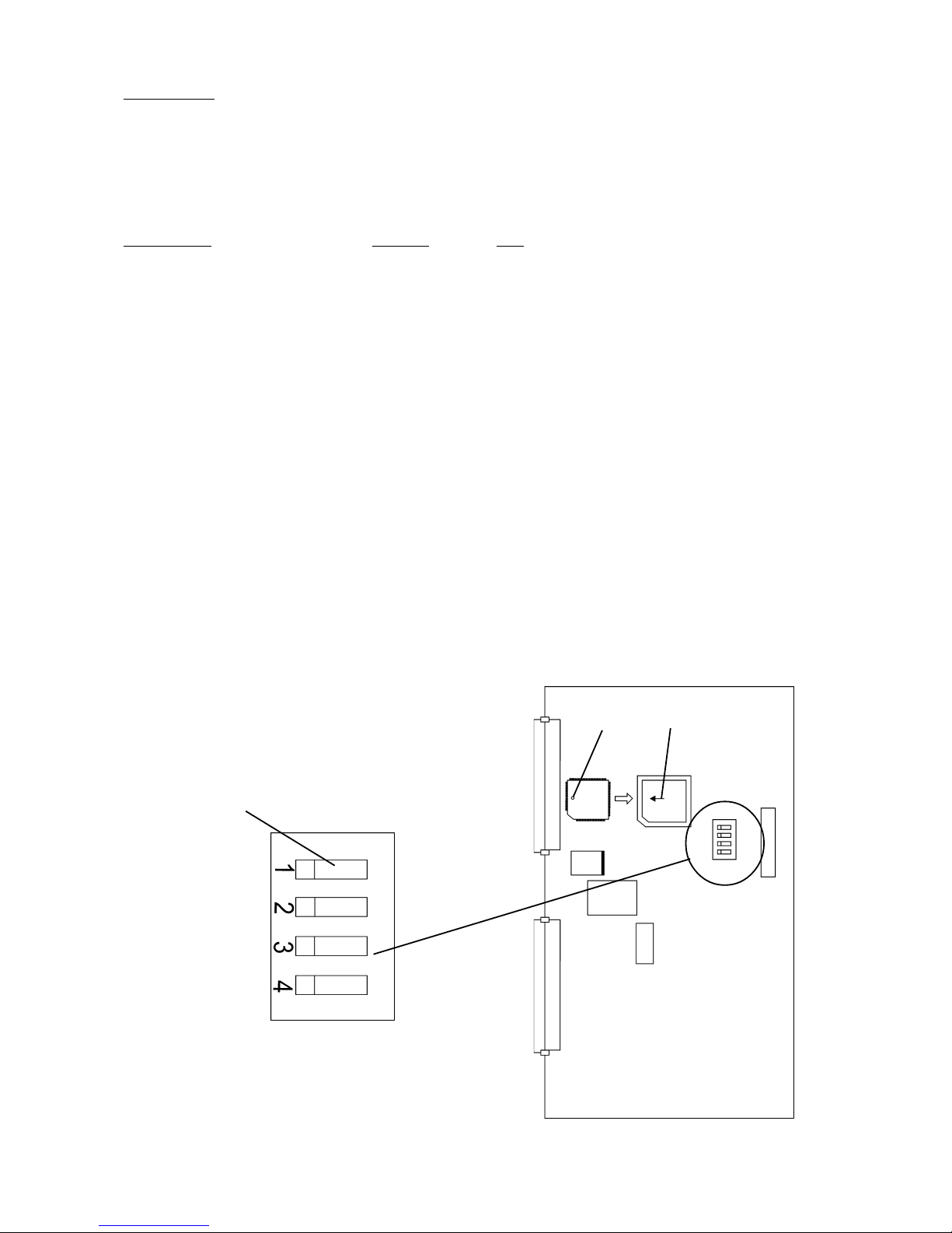
Upgrade the software in SR85 if the software is below V5.02. Follow below procedure:
1. Switch off main power.
2. Remove rear cover.
3. Remove the microprocessor by using an Extractor tool. Read Caution below.
4. Insert the new microprocessor with the dot “A” positioned corresponding
to the arrow “B”.
5. To reset the EEprom, move the DIPswitch no. 1 on the controller PCB to the right
(right when facing the PCB).
6. Switch on the main power.
Note: The ADJUST LED on the control panel is flashing.
7. When the ADJUST LED stops flashing, switch off the main power.
8. Move the DIP switch no.1 on the controller PCB to the left ( left when facing the PCB)
9. Mount the rear cover.
10. Switch on the main power.
Caution: Always handle the circuit board in accordance
with electrostatic discharge procedures. The circuit
board and microprocessor are sensitive to ESD damage.
Normal mode < > Reset EEPROM
A
B
November 2001
Part no. 75952
1
(5)
T09149
2
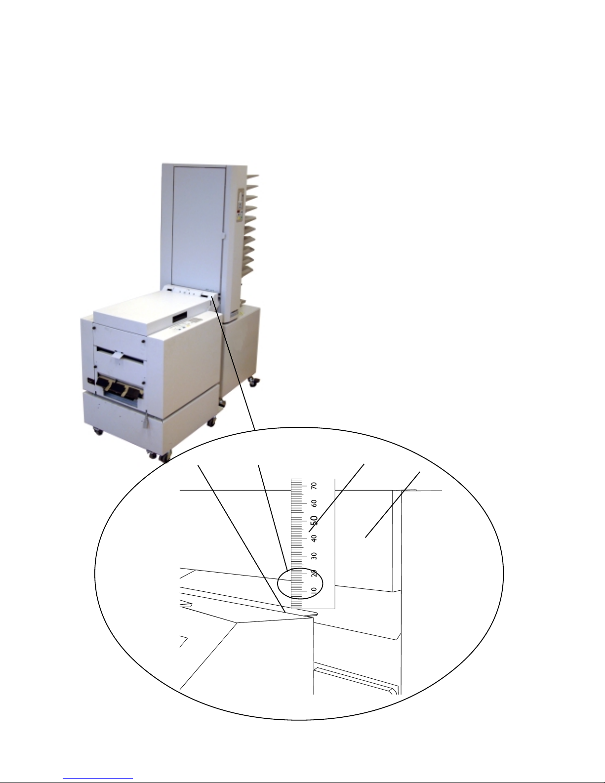
Height adjustment:
1. Push the machines together.
2. Place a scale (1) on the stainless plate (2) on the infeed unit at SR85. Adjust the
height to approximately 15 mm to the lower edge of the door of Model 306/310 by
adjusting the height on the castors of the Collator base.
Note: Do not adjust the height of the SR85.
Approx.15 mm
1
2
Door
 Loading...