

Page 1
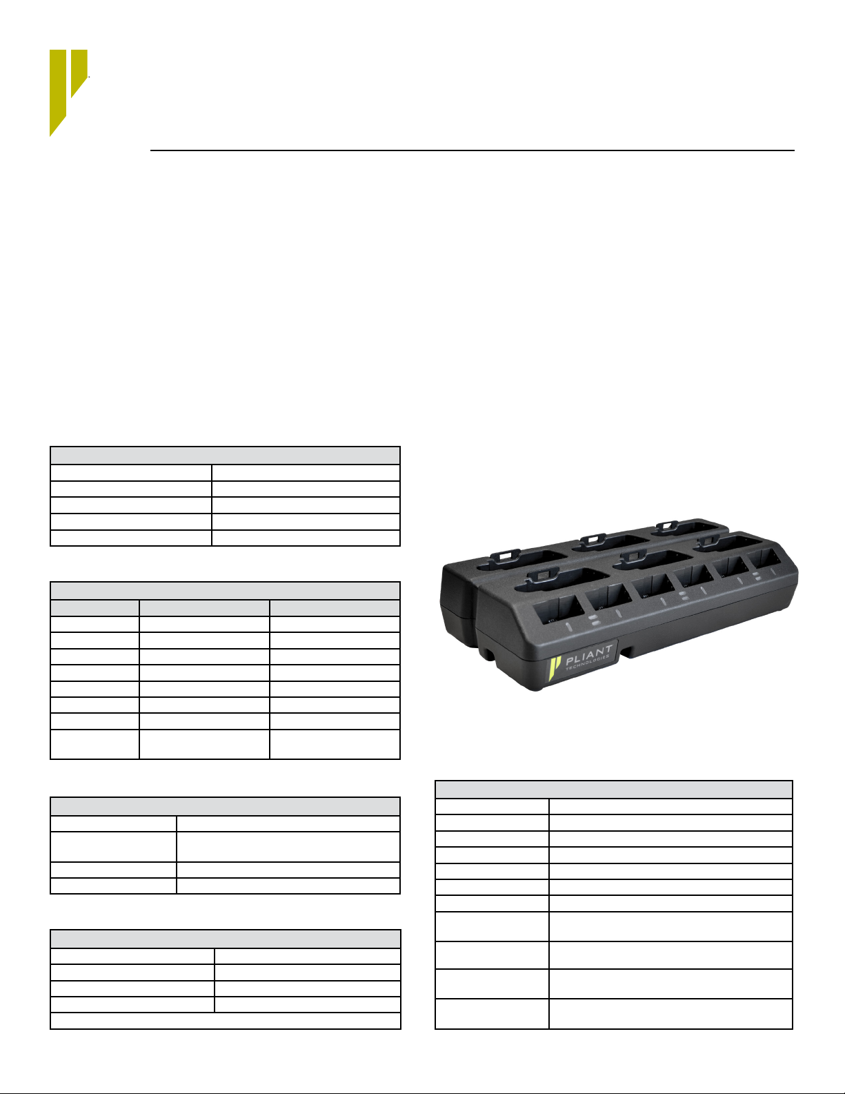
6+6 Drop-In Radio Pack and Battery Charger
Product Specications
PBT-RPC-66
Overview
This 6+6 Drop-In Radio Pack and Battery Charger is a customized charging station for CrewCom® Radio Packs (RPs) and Pliant rechargeable Li-Poly batteries. When ordering, reference Part Number
PBT-RPC-66.
Key Features
• Charge up to six CrewCom Radio Packs and six batteries simultaneously
• Recharge batteries from empty in less than 4 hours
• LED indicators provide real-time charge status
• Radio Pack charging bays compatible with Pliant FleXLR adapter
• Charger bottom designed for cable management
• Region-specic power cable (included)
• Non-Reective, textured matte nish
• Optional mounting bracket available (not included)
• Full One-Year Parts and Labor Warranty
Specications*
Input
Voltage Range 90–264 VAC
Frequency Range 47–63 Hz
Input Current 1.3 A max
Standby Power 1.6 W max
Input Fuse N/A
Output
Per Battery Bay Per RP Bay
Voltage 0–4.2 V 0–5.35 V
Current 0–1 A 0–1.5 A
Power 4.2 W Maximum 8 W Maximum
Voltage Tolerance ± 1% ± 1%
Current Tolerance ± 5% N/A (controlled by RP)
Leakage Current <1 mA <1 mA
Ripple & Noise (3) <120 mV pk-pk <120 mV pk-pk
Protection Over current, Over
temperature, Reverse polarity
Over current, Over
temperature, Reverse polarity
What’s in the Box?
• PBT-RPC-66 6+6 Drop-In Radio Pack and Battery Charger
• 00004239 Power Supply
• PC-PWR-XX (Region Specic) AC Power Cord
• D0000534 Operating Guide
• D0000219 Warranty Extension Registration Card
Accessories
• PAC-PBT-MNT Mounting Bracket
PBT-RPC-66 Drop-In RP and Battery Charger
Environmental
Cooling Convection cooled
Operating Temperature Supply: -30°C to 70°C (-22°F to 158°F);
Battery Charging: 0°C to 45°C (32°F to 113°F)
Non-Operating Temperature -40°C to 70°C (-40°F to 158°F)
Altitude -382 m to 2000 m (-1,253 ft. to 6,562 ft.)
Mechanical Details
Dimensions (Charger) (L×W×H) 394 × 173 × 78 mm (15.5 × 6.8 × 3.1 in.)
Weight (Charger) 1360 g (3 lb)
Dimensions (power supply) (L×W×H) 145 × 60 × 32 mm (5.7 × 2.4 × 1.2 in.)
Weight (power supply) 450 g (1 lb)
Dimensions may vary if device uses optional mounting bracket.
General
AC Input Connector IEC60320 C14 (3-in)
DC Input Connector L712
DC Cable Length 1 m (3.3 ft.)
Efciency (Level VI) >89% at full load
Green Procurement WEEE2002/96/EC
MTBF 348.7K hrs. min. MIL-HDBK-217F (25°C)
Indicator Red-green bicolor LED per bay
Battery Temp Monitoring Read TEMP register (0x07 – 0x06) of BQ27000 in battery
pack
Charge Time from Empty Radio Packs: approx. 4 hours
PCB Visibility < 0.5 mm (0.020 in.) around perimeter of battery-mating
RoHS COMPLIANCE
Batteries: approx. 2.5 hours
connector
In compliance with the European Directive 2011/65/EC on the
Restriction of Hazardous Substances (RoHS)
1
Page 2
Specications* Continued
Charge Phases and Indicators
Current Phase Description LED Color
Charging Normal (constant current constant voltage or "CCCV") charge mode Solid Amber
Charge Complete Battery is fully charged Solid Green
Fault No battery communication Solid Red
Extreme Temperature Over 45 C or under 0 C Blink Red
Standby No battery inserted None (LEDs off)
Power On Charger verication of power at power up All device LEDs ash once Red, Amber, and
Green in sequence
Waiting for Update Device has successfully connected to CrewWare, but awaiting user action to proceed with rmware update Blink Green
Firmware Update Failure Device has successfully connected to CrewWare, but previous device update failed. Device recovery
required via instructions in Crew-Ware.
Update in Progress Device rmware update in progress Solid Amber
Charge Termination Methods
Cutoff Charge is terminated when the charge current is less than 65 mA at a charging voltage of 4.2 V
Temperature Charge will not occur if below 0°C (32°F) or above 45°C (113°F)
Compliance
Safety & EMC
IEC 60950-1, Edition 2.2 Safety
Emissions
CISPR 32:2008 with TRF IECCISPR22B CB Scheme - Radiated Emissions
CISPR 24:2010 with TRF IECCISPR24B CB Scheme - Immunity Testing
IEC 61000-3-2:2014 with IEC61000_3_2C CB Scheme - Conducted Emissions
IEC 61000-3-3:2013 with TRF: IEC61000_3_3C CB Scheme - Voltage Fluctuations and Flicker
AS/NZS CISPR 32 Australia - EMC Testing
VCCI CISPR 32 Japan - EMC Testing
KN 32 South Korea - Radiated Emissions
KN 35 South Korea - Radiated Emissions
EN 61000-3-2:2014 South Korea - Conducted Emissions, Harmonics
EN 61000-3-3:2013 South Korea - Conducted Emissions, Flicker
FCC
FCC Part 15, Subpart B and ICES-003 Issue 6 Nonintentional Radiated & Conducted Emissions, Class A limits
Supply Immunity
EN 61000-4-2 Electrostatic discharge (ESD)
EN 61000-4-3 Radio-frequency electromagnetic eld
EN 61000-4-4 Electrical fast transients/burst
EN 61000-4-5 Surges
EN 61000-4-6 Conducted high frequency disturbances
EN 61000-4-8 Power-frequency magnetic elds
EN 61000-4-11 Voltage variations, dips and interruptions
None (LEDs off)
Notes
1. Ambient temperature Ta = 20ºC unless
otherwise indicated.
2. Load regulation is measured at the
battery connector.
3. Measured with a 0.1μF ceramic capacitor
and a 47μF Tantalum capacitor across
the output terminals.
4. Total regulation tolerance includes initial
set accuracy, line and load regulation.
5. Power losses of input and output cables
are not considered here.
6. The rms method is used for leakage
current measurements.
Pliant Technologies, LLC
®
CrewCom
205 Technology Parkway
Auburn, Alabama 36830 USA
www.plianttechnologies.com
Phone +1.334.321.1160
Toll-Free 1.844.475.4268 or 1.844.4PLIANT
Fax +1.334.321.1162
* Notice About Specications: While Pliant makes every attempt to maintain the accuracy of the information contained in this document, this information
is subject to change without notice. Please check our website for the latest system specications and certications.
Copyright ©2019–2020 Pliant Technologies, LLC. All rights reserved. The Pliant® and CrewCom® word marks and the Pliant “P” logo are trademarks of Pliant
Technologies, LLC. All other trademarks are property of their respective owners.
PBT-RPC-66_DATASHEET_02.20
2
 Loading...