

Pliant Tempest TMA-RTEXT-01 Quick Start Manual
Quick Start Guide
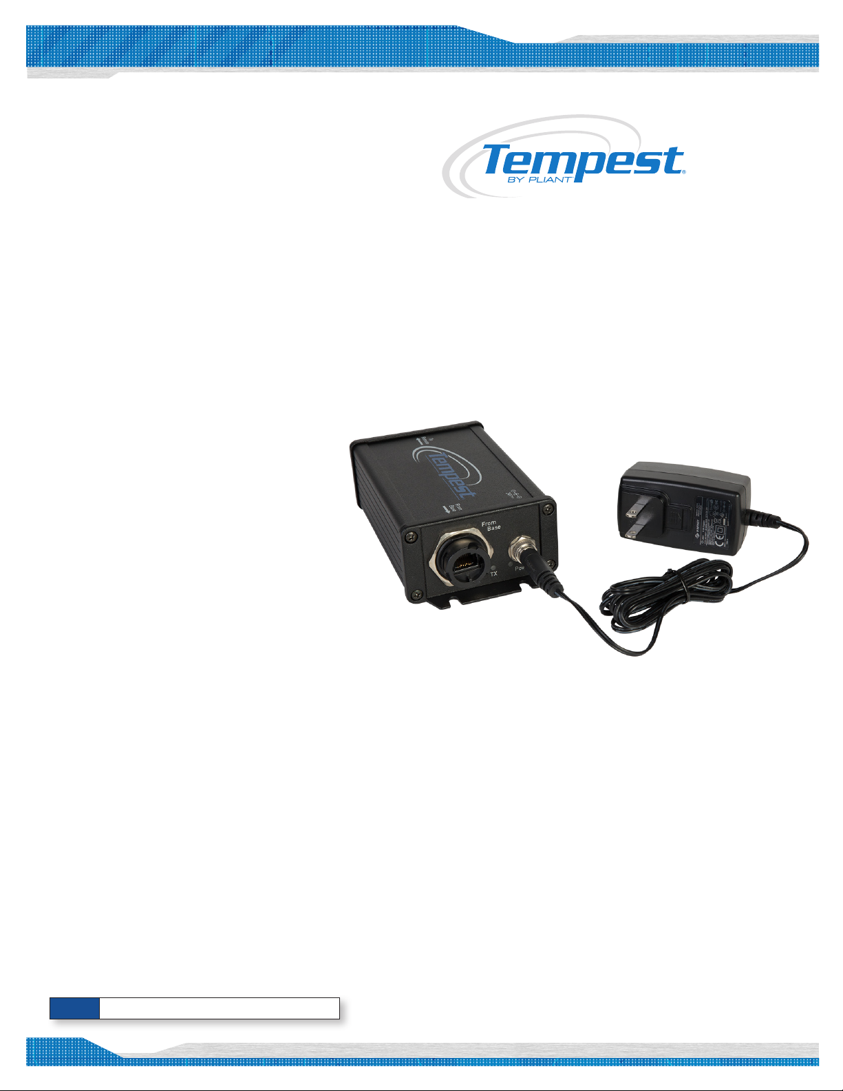
Tempest Remote Transceiver Line Extender
Quick Start Guide
What’s in each box:
• Remote Transceiver Line Extender (TMA-RTEXT-01)
• Power Supply
• International blades for mains connection (x2)
What else you may need:
• Tempest2400 or Tempest900 BaseStation
• Tempest Remote Transceiver (RT)
• 100% copper twisted pair CAT-5 cable
• Tempest BeltStations with headsets attached
Important things you need to know:
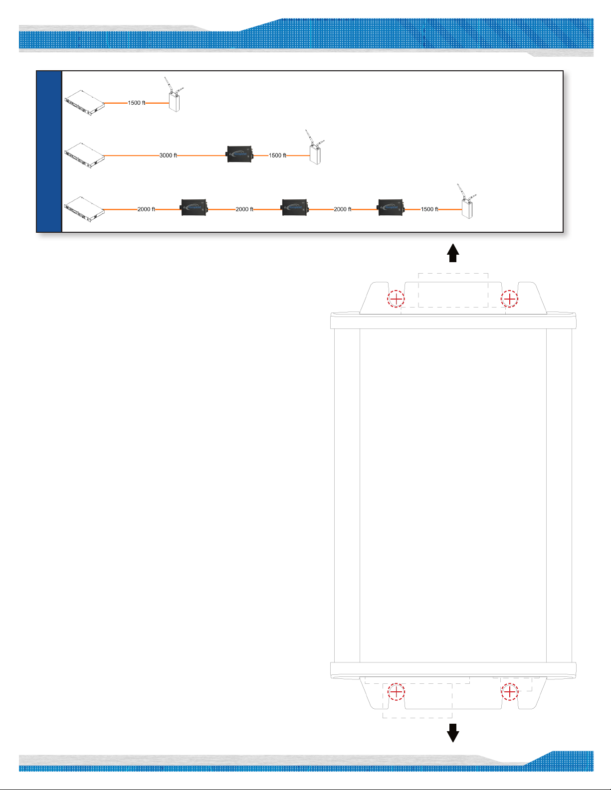
• Maximum distance of cable run from BaseStation to RT
is 1500 ft.
• Maximum distance of cable run from RT Line Extender
to RT is 1500 ft.
• Maximum distance of cable run from BaseStation to
RT Line Extender is 3000 ft. when using one RT Line
Extender
• Maximum distance allowable using multiple RT Line
Extenders is 2000 ft. from BaseStation to RT Line
Extender and to each additional RT Line Extender, to a
maximum of 3.
• Maximum distance allowable from BaseStation to
RT is 7500 ft. by way of a maximum of three RT Line
Extenders.
Note: Unit requires local power for proper operation.
Pliant Technologies, LLC
205 Technology Parkway
www.plianttechnologies.com
Phone +1.334.321.1160
Toll-Free 1.844.475.4268 or 1.844.4PLIANT
Copyright © 2016 Pliant Technologies, LLC. All rights reserved. The Pliant™ word mark and
the Pliant “P” logo are trademark s of Pliant Technologies, LLC. The Tempest® word mark and
Tempest® logos are trademarks of CoachComm LLC. All other trademarks are property of their
RTLineExtenderQSG_D0000161_C
Tempest
Auburn, AL 36830
Fax +1.334.321.1162
respective owners.
®
1
Setup Instructions
** With the BaseStation(s) powered off **
Quick Start Guide
Maximum Distance = 1500 ft
Maximum Distance = 4500 ft
Maximum Distance = 7500 ft
TO REMOTE
1. Select Location of BaseStation/RT Line Extender/R T.
2. Connect Cat5 cable from BaseStation “Transceiver” port to RT Line
Extender “from Base” port.
3. Connect Cat5 cable from RT Line Extender “to Remote” port to RT
“BaseStation link” port on RT.
4. Connect power to RTLEx.
5. Power on BaseStation.
6. Check power and TX lights on RT Line Extender and Power, Sync, and
TX lights on RT to insure system operation.
7. Power on BeltStations and walk-test your system to conrm
performance.
Note: The RX light on the RT Line Extender and RT
will only be lit when a BeltStation is logged in.
Tips
• Water tight operation is possible for the Cat5 connections on the RT
Line Extender. Please contact TE at http://www.te.com/ and reference
part number 1738607-1 for more information.
• Distances discussed and shown on the diagram are approximate and
have been tested using 100% copper twisted pair Cat5 cable.
• Use of copper clad solid aluminum-core Cat5 cable signicantly
reduces distances and/or performance quality of your system.
• Use caution when mounting, especially near foot trafc areas; never
mount directly overhead.
• Use installation template provided for assistance installing securely &
accurately.
• If using ZSync, ensure all BaseStations are powered on and all RT Line
Extenders and RTs are powered on and operational at all times.
• For multiple BaseStations, roaming installations, and detailed
synchronization considerations, contact Pliant for more information.
INSTALLATION TEMPLATE
Line up the RT Line Extender
template and use the crosshairs in
the red dotted circles as reference
points for screw placement.
Note – This template is t to scale.
FROM BASE
© 2012 HM Electronics, Inc All rights reserved.
2
 Loading...