

Radio Pack
OPERATING MANUAL
®

RADIO PACK MANUAL
Thank You
We at Pliant® Technologies want to thank you for purchasing CrewCom®. Pliant brings our experience, expertise, and commitment
to quality technology with the new CrewCom System. In order to get the most out of your new CrewCom product, please take a few
moments to read this manual completely so that you better understand the operation of this product. For questions not addressed
in this manual, feel free to review the additional support documentation provided on our website or to contact Pliant’s Customer
Support Department:
Pliant Technologies, LLC
205 Technology Parkway
Auburn, AL 36830 USA
www.plianttechnologies.com
Phone: +1.334.321.1160
Toll-Free: 1.844.475.4268 or 1.844.4PLIANT
Fax: +1.334.321.1162
Copyright © 2018 Pliant Technologies, LLC. All rights reserved. The Pliant®, CrewCom®, and CrewNet™ word marks and the Pliant
“P” logo are trademarks of Pliant Technologies, LLC. Any and all other trademark references within this document are property of
their respective owners.
Model Information
This document applies to models CRP-44-900, CRP-44-900AN, CRP-22-900, CRP-22-900AN, CRP-44-2400,
CRP-44-2400CE, CRP-22-2400, and CRP-22-2400CE.
CRP-22-900 and CRP-44-900 models are only available in North America and operate within the 902–928 MHz frequency range.
CRP-22-900AN and CRP-44-900AN (Oceania) models are approved for use in Australia and New Zealand and operate within the 915–928 MHz frequency range.
CRP-44-2400CE and CRP-22-2400CE models meet the same specications as the CRP-44-2400 and CRP-22-2400 models, and they comply with ETSI standards (300.328
v1.8.1). Non-CE models are non-compliant with some ETSI standards.
Document Reference: 2018.09 D0000215_B
ii

RADIO PACK MANUAL
Table of Contents
Safety Information ................................................................................................................................................1
Safe Operation and Service .............................................................................................................................1
Battery Safety ................................................................................................................................................1
Firmware Version 1.2 Release Notes ......................................................................................................................2
Introduction ..........................................................................................................................................................5
What’s in the box? ..........................................................................................................................................5
Additional Items Required ...............................................................................................................................5
CrewCom Overview ........................................................................................................................................5
CrewCom Conguration File Overview .............................................................................................................7
Product Overview ..................................................................................................................................................9
CRP-44 Model ...............................................................................................................................................9
CRP-22 Model ..............................................................................................................................................11
Radio Pack LCD Display .................................................................................................................................12
Radio Pack Battery System ...........................................................................................................................13
Setup and Installation..........................................................................................................................................14
Installing a Radio Pack Battery .....................................................................................................................14
Charging a Radio Pack ..................................................................................................................................14
Pairing a Radio Pack (to a Control Unit) .........................................................................................................15
Operation ............................................................................................................................................................16
Understanding Link Quality ..........................................................................................................................16
Pack Information ...........................................................................................................................................16
Device Settings .............................................................................................................................................17
User Settings ................................................................................................................................................19
Tech Menu ....................................................................................................................................................22
Radio Pack Menu .........................................................................................................................................23
Headset Connector Pinout and Wiring ...........................................................................................................23
Product Specications ........................................................................................................................................24
Product Support ..................................................................................................................................................25
Returning Equipment for Repair or Maintenance ...........................................................................................25
Maintenance and Storage ...................................................................................................................................26
Cleaning .......................................................................................................................................................26
Temperature and Humidity ............................................................................................................................26
Storage of your Lithium-Polymer Batteries .....................................................................................................26
License Information ...........................................................................................................................................27
RF-Exposure Statement .................................................................................................................................27
CrewCom Compliance Numbers ....................................................................................................................28
Warranty Information ..........................................................................................................................................29
Limited Warranty ...........................................................................................................................................29
Parts Limited Warranty ..................................................................................................................................29
Glossary ..............................................................................................................................................................30
Index ..................................................................................................................................................................33
iii
Safety Information
RADIO PACK MANUAL
Safety Information
The following section details important safety information related to the ownership and operation of the CrewCom Radio Pack.
WARNING: Indicates a situation, which, when not avoided, has the potential to result in death or severe injury.
CAUTION:
1. Read these instructions.
2. Follow all instructions.
3. Heed all warnings.
Safe Operation and Service
• Clean only with a dry cloth. Do not spray household cleaners or water onto the cloth. Never spray household cleaners or
water onto any part the unit.
• Use only attachments/accessories that are specically made for or certied by Pliant Technologies with the Radio Pack.
Indicates a situation, which, when not avoided, results or has the potential to result in minor
injury or product failure or damage.
• Unplug the Radio Pack charger during periods of inclement weather and after use.
• Do not charge the Radio Pack outdoors. The charger is designed for indoor use only.
• Refer all Radio Pack service to qualied Pliant Technologies personnel. There are no user-serviceable parts
inside the CrewCom Radio Pack. Opening the unit may expose dangerous electrical components, which will result in
product failure. Any attempt to self-service or self-repair the unit will void the product warranty.
• Service is required if the Radio Pack receives any type of damage to any of its parts or if it does not operate normally.
For example, if water or any other type of liquid has been spilled on the Radio Pack or if it has been exposed to rain or
moisture, then service is necessary. Service is also required if debris or other objects have fallen into the unit or if it has
been dropped.
Battery Safety
WARNING: DANGER! EXPLOSIVE GASES RISK
• Battery explosion is possible if incorrect type is used. Use only batteries approved for use with CrewCom Radio Packs.
• Do not leave the battery unattended while charging. Immediately unplug unit if battery begins to swell or emit smoke
while charging. If battery bursts or chemicals begin to leak out of battery housing, the chemicals will react with the air
and cause a re.
• Pliant Technologies recommends keeping a Class-D re extinguisher available when charging lithium-polymer batteries.
The chemicals inside lithium-polymer batteries are highly ammable.
• Do not allow batteries to overheat (reach temperatures of above140 degrees Fahrenheit (60 degrees Celsius)).
• Batteries that appear swollen, deformed or damaged, or that do not t properly should never be used. Properly dispose of
any batteries in this condition in accordance with the instructions provided by your local authorities. For more information
and local drop-off sites, visit http://www.call2recycle.org/.
1
Firmware Version 1.2 Release Notes
RADIO PACK MANUAL
Firmware Version 1.2 Release Notes
The following document is a list of features implemented with the latest CrewCom® rmware release.
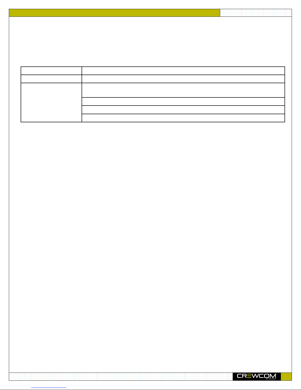
Firmware Details:
Version
Release Date
Affected Models
Compatibility Note: To work together as a system, all connected devices must have rmware that matches the version
installed on the Master Control Unit.
1.2.0.0
September 28, 2018
CRP-22-900, CRP-44-900, CRP-22-2400, CRP-22-2400CE, CRP-44-2400, CRP-44-
2400CE
CRT-900, CRT-2400, CRT-2400CE
CCU-22, CCU-44
CHB-8C
Device Parameters:
CrewNet supports the following:
• Up to 4 Control Units (CUs)
• Up to 72 Radio Packs (RPs): 4 CUs × 18 RPs per CU
• Up to 16 Radio Transceivers (RTs): any combination of 2.4 and 900*
• Up to 4 layers of Hubs (See Operational Notes for more information on Hub layers.)
• Up to 32 wired intercom/audio channel inputs (maximum of 16 2-wire and 16 4-wire across 4 CUs)
• Up to 64 Proles
• Up to 64 Conferences
• This rmware version is not yet compatible with the following device models: CRP-22-900AN, CRP-44-900AN, and
CRT-900AN.
*Maximum of 14 900MHz RTs on any single system (out of 16 total RTs). Systems may contain an even or odd number of RTs.
Feature Notes:
• The Master CU is the control host for the CrewWare application via the LAN port.
• Available RP Function button options include Stage Announce and Call.
• Call on Talk is now supported.
• Stage Announce Relay is now supported.
• Auxiliary Audio Input (program audio) and Output are now supported. Audio supplied to Aux In can be assigned to
any combination of up to 10 possible conferences. Audio supplied from Aux Out can be assigned from any single
conference.
• Up to 4 Hub layers can be congured. The number of Hub layers is dened by how many Hubs are between the
device and the Master CU.
• The following functions are not yet supported: GPIO Relays, Ping, High Density mode, User Access Rights
management, hardwire Mic Kill, and CrewWare multi-client access to one system.
2

Firmware Version 1.2 Release Notes
• The following CU menu options are not operational: Sync Priority, Device Settings (CU menu), RT Hopping Patterns,
and RT Radio Band; however, these settings can be managed via CrewWare while ofine (requires save/upload of
new CrewCom Conguration File (.ccf)).
» By default, the rst Control Unit added to the CCF is automatically assigned the Master sync priority. Every
CCF must contain one Master Control Unit. Secondary and Tertiary sync priority assignments are not currently
operational.
• Out-of-the-box dynamic conguration of hardware is not yet supported. CrewWare is required to build a
conguration les (.ccf).
RADIO PACK MANUAL
Enhancements:
• Updated CrewWare user interface to remove/disable non-operational features that were previously visible.
• Added ability to upload CCF to your system from CrewWare via network LAN connection.
Operational Notes:
Firmware Updates
• The user will need to disable the Windows rewall in order to install CrewWare.
• When updating rmware from previous versions via USB, devices may require additional rescan. See the “How to
Update Firmware via USB” tutorial and/or the CrewWare Manual for further detailed instructions on this process.
• Following system rmware updates, a complete power down and restart of system is recommended. Upon restart,
Radio Transceivers will nish updating the radio. This will be evident by the alternating ashing of the RX and TX
lights. Once this sequence ends per RT, the device is ready. See the “How to Update Firmware” document and/or
the CrewWare Manual for further detailed instructions on this process.
Conguration and Startup
• If updating from rmware version 1.1 or older, you must save your CCF in the new version to match existing
settings to added features. Do so with the following steps:
» After updating device rmware, connect CrewWare to your CU via LAN connection, and go “live.”
» In CrewWare, click
and save it. This CCF is now updated.
» In CrewWare, click
CrewWare and CU prompts to upload the le and restart your system.
• Moving device port or connection locations will cause conguration errors at startup. Pliant recommends avoiding
connecting devices to a port different than that in the CCF.
» Once the system is powered on, you can tell that a conguration error has occurred with the system if the TX
LED on one or more connected RTs is not lit and if the associated RPs do not log in. The conguration error
may be present in the RT or other device upstream. If you are connected to CrewWare, it will alert you of any
rmware or conguration errors needing resolution.
File
File
then
Save File As...
then
Upload File...
; then select a le location, name your le (8 characters or less),
, then navigate to your saved le (.ccf) and choose it. Follow the
• CCF uploads from USB and from CrewWare are now supported.
» Uploading the CCF via USB is done by saving the .ccf from CrewWare to a USB drive, manually uploading the
saved le to the Master CU, and rebooting the system once more. Deleting the old CCF is no longer a required
step of this process.
» Uploading the CCF via CrewWare is done by selecting the
While uploading, CrewWare will notify you of any conguration exceptions. Follow the CrewWare prompts for
the upload and reboot your system when prompted by the CU LCD.
Upload File...
option from CrewWare’s le menu.
3

Firmware Version 1.2 Release Notes
• Adding and removing devices (such as an RT) in live mode (often referred to as “hot-plugging” or “hot-swapping”)
may cause system errors to occur. Pliant recommends only performing this type of action when the system is
powered off.
• Upon startup, non-Master CU(s) (if applicable) may require up to 60 seconds to complete the CCF load. The LCD
screen will display load progress messages during this time.
• Any change to RF parameters such as hopping pattern or radio band will require RPs to be repaired.
• To avoid an RP going inactive, Pliant recommends ensuring your CUs and RTs are powered on and ready prior
to powering on the RPs. An RP will enter inactive mode if it cannot establish communication with an RT. If an RT
becomes available, an inactive RP can be prompted to attempt to re-establish communication by pressing the RP
Menu button.
• Changes to CU port names made in live mode do not save in the CCF. To save changes, save the .ccf from
CrewWare, reload the le to the system from CrewWare, then reboot the system.
• Pliant recommends that Hubs be externally powered with local power supply (provided).
RADIO PACK MANUAL
LAN Settings
• When changing LAN settings from the CU front panel, a reboot is required before operation. Pliant recommends
waiting about 60 seconds after making the change before powering off the CU.
• Disconnecting the LAN connection while in live mode will require a system restart to reconnect CrewWare to the
Control Unit; therefore, Pliant recommends only performing this type of action when the system is powered off.
CrewWare Interface
• CrewWare’s “Device Management” tab (individual device detail view) does not currently populate with the accurate
Radio Version or Powered By data (for RTs). It also does not populate with the accurate Operational Status indicator
(for CUs and RTs). This does not affect operation.
4

Introduction
Introduction
What’s in the box?
• Radio Pack
• Lithium-Polymer Rechargeable Battery
• USB A to Micro B Cable
• Multi Blade Worldwide Battery Charger/Power Supply
• Product Overview Guide
• Warranty Registration Card
Note: A one-year product warranty is standard with CrewCom products. Follow the product registration
instructions on the Warranty Extension Registration Card and visit www.plianttechnologies.com/customer/
account/login to extend your product warranty to two years at no charge. See page 28 for more
information about Pliant warranties.
RADIO PACK MANUAL
Additional Items Required
In addition to your Radio Pack, at least one of each of the devices listed below is required to complete your CrewCom System (sold
separately with included components):
• Control Unit
• Radio Transceiver
• Headset
CrewCom Overview
CrewCom is a versatile yet straightforward communications solution built on an intelligent wireless and wired network-based
distributed system architecture. Innovative technologies have been specically developed to facilitate intercom system growth
and effortless adaptation, along with unparalleled digital wireless reliability for consistent operation, even in the most demanding
production environments.
Decentralized Network Architecture
The CrewCom system utilizes a proprietary network backbone, known as CrewNet™, to coordinate and transport all system timing,
audio, signaling, and controls. This efcient, decentralized resource network delivers increased exibility over that of traditional
technologies, using a distributed network-to-device intelligence within a modular building block structure. System components can
easily be placed where they are needed or scaled to facilitate system growth, reconguration, and effortless adaptation to changing
environments. For increased infrastructure exibility, the CrewNet network is capable of operating over standard Cat 5e (or greater)
and/or Single Mode Fiber (SMF) lines.
5

Introduction
RADIO PACK MANUAL
Flexible RF Platform
CrewCom’s RF platform is vast and exible to meet the needs of virtually any wireless communication challenge facing production
and entertainment professionals worldwide. Each CrewCom wireless product is available in the 2.4GHz and 900MHz (North
America, Australia, and New Zealand only) ISM bands and any combination of these frequency ranges may be simultaneously
used on the same CrewCom system. CrewCom makes it easy to operate in challenging RF environments by combining support for
multiple simultaneous frequency bands, while also allowing for simple system setup without the need for an RF engineer.
In addition, a more robust RF link enhances RF range and reliability through a newly developed dual carrier double-send
transmission scheme that minimizes the adverse effects of inter-symbol interference. This innovation allows increased useful RF
range and improved performance, especially in large, reective environments.
Intuitive User Experience
CrewCom’s family of products is designed around a system architecture that offers a high density of users with a more manageable
infrastructure and lower cost per user than typically found in large-scale wireless installations. The CrewCom system not only
consists of a range of wired and wireless hardware products but also incorporates an intuitive software application, known as
CrewWare, working together with the system hardware to enhance the experience of system administrators, designers, integrators,
and users. Each device’s user interface allows a quick learning curve with high functionality, and its ease of use is consistent across
all frequency bands, types of users, and applications.
CrewCom Devices
The following is a list of available CrewCom devices. For more information on each of these products and their conguration
capabilities, visit our website at: www.plianttechnologies.com
• Control Unit (CU) – the 1RU foundational element of the CrewCom system that establishes the CrewNet-based
infrastructure while also providing external connections to common established intercom systems. Unlike traditional
BaseStations, the CU contains no radio and is frequency agnostic, which sets the groundwork for a multi-frequency
capable system. For maximum exibility, any CU can access, control, and monitor any active device across CrewNet. The
CU is available in a “CCU-22” or “CCU-44” model, which simultaneously support up to (2) 2-Wire and (2) 4-Wire or (4)
2-Wire and (4) 4-Wire intercom connections, respectively.
• Radio Transceiver (RT) – a CrewCom radio device that houses a radio (2.4GHz or 900MHz) and its corresponding
antennas, enabling RF communications to CrewCom Radio Packs. Using the CrewNet network as the system’s backbone,
RTs can be positioned throughout a wide coverage area by being linked back to a Control Unit either directly or through
a Hub(s). Connectivity is accomplished using either Cat 5e (or greater) or Single Mode Fiber (SMF).
• Radio Pack (RP) – the direct portable wireless communication device connecting individual CrewCom users to the
CrewCom system. Each RP provides full duplex audio communications and, through customized function buttons, GPO
control and event logging. The RP requires a connected headset and access to a Radio Transceiver on the CrewCom
system. Devices are available in 2.4GHz and 900MHz bands as well as two and four volume/talk button congurations.
• Copper Hub – a CrewNet-based device with eight ports to allow extended interconnection for a variety of CrewCom
hardware. Ports one through seven are copper (RJ-45, Cat 5e, or greater); port eight can be either an additional copper
port or a duplex LC Single Mode Fiber port, but only one may be used at a time. The Hub provides for extensive system
expansion and exibility.
• Fiber Hub – a CrewNet-based device with eight ports to allow extended interconnection for a variety of CrewCom
hardware. Ports two through eight are duplex LC single-mode ber ports; port one can be either an additional ber port
or a copper port (RJ-45, Cat 5e, or greater), but only one may be used at a time. The Hub provides for extensive system
expansion and exibility.
6

Introduction
RADIO PACK MANUAL
CrewCom Conguration File Overview
The CrewCom system operates using a CrewCom Conguration File (CCF) to coordinate the processes and data that make up the
system’s operation. A default CCF is available for your CrewCom system out of the box to provide your initial settings. You can use
CrewWare to customize your conguration to meet your specic needs beyond the default settings. The CCF stores the settings for
your Conferences and Proles, intercom settings, and connection information for your 2-Wire, 4-Wire, and CrewCom devices.
Conferences and Proles work together to create channels of communication between CrewCom users. They are dened for each
user, stored in the CCF, and available each time you set up. For more information about Conferences and Proles, continue reading
the following sections for their denition.
About Conferences
A CrewCom Conference is an administrator-dened grouping of audio entities (inputs such as Radio Packs, wired intercom ports,
etc.). Audio outputs are then created dynamically by mixing one or more audio entities and routing them to Conference subscribers
accordingly. This method of subscription-based audio using Conferences is very powerful. Point-to-point associations may also be
easily constructed using this method. Each association requires a separate, unique Conference. Conferences in CrewCom are full
duplex (i.e. bidirectional) and there can be a maximum of 1,024.
Default Conferences are included as part of a system’s default conguration. New Conferences can be created using CrewWare.
About Proles
Each Radio Pack has a Prole that contains a variety of system settings that are dened as either global prole settings or user
settings. A Radio Pack Prole assigns functionality to an RP’s local controls, knobs, and buttons (including Conference assignments),
and allows customization for user preferences and roaming
• Global Prole Settings - These settings are part of the CrewCom Conguration File and are usually assigned by
a system administrator through customization in CrewWare during setup. Find a full list of the global prole settings
available for each Radio Pack in the CrewWare Operating Manual or the Radio Pack Operating Manual.
• User Settings - A user setting is one that is classied as being adjustable by the Radio Pack user and is limited to local
device settings that do not alter the CrewCom Conguration File. The Prole can be used to determine these settings, but
they can also be customized directly from a Radio Pack after a Prole is loaded.
7
Introduction
RP Prole Settings
A prole is part of the CrewCom Conguration File and contains a variety of system settings that are dened as either system level
settings or user adjustable settings. A system setting is one that assigns specic operational functions to a Pack’s volume knobs, talk
buttons, and function buttons, along with relay assignments and roaming options. A user setting is one that is classied as being
adjustable by the device user and is limited to local device settings that will not alter the CrewCom Conguration File. These settings
can be set in the prole and/or adjusted separately at the Pack, via the Control Unit’s menu, or via CrewWare. A list of the specic
functions within each setting type is provided in Table 1.
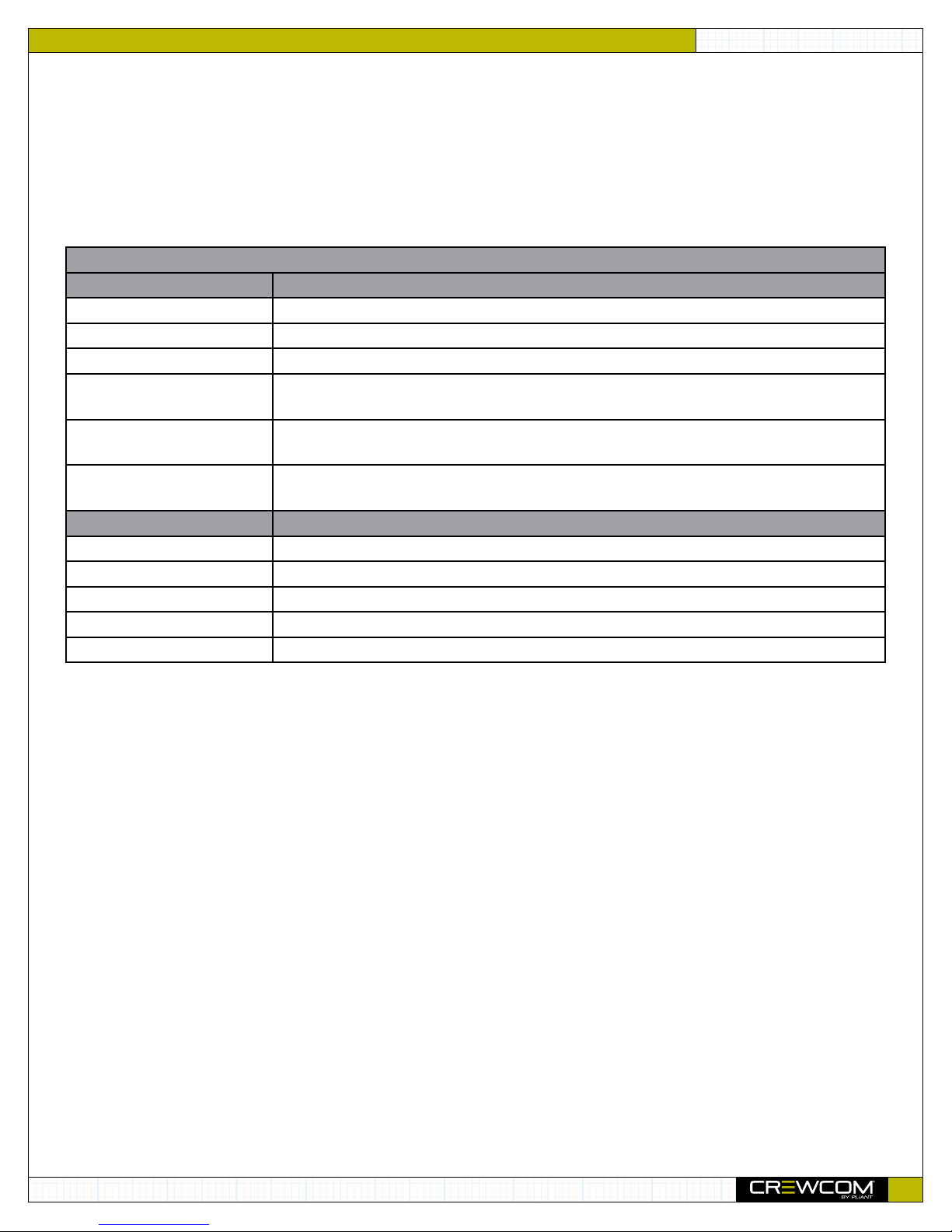
Table 1: Prole Management Settings
Global Prole Settings Description
Prole Name Name assigned to the Prole
Radio Transceiver Scan List Which Radio Transceiver each Radio Pack can log into and function with
Conference Assignments Which Conferences are assigned to Volume knobs and corresponding Talk buttons
ISO Enables selection of specic Proles to include in a Conference ISO. This function is either
Enabled or Disabled. (ISO must also be enabled for the Conference.)
Function Buttons Functions such as Stage Announce, Call, GPO, or IFB Send are assigned to the Pack’s F1 or F2
button
Button Mode Determines the talk button behavior as either “Latch,” “Momentary,” “Disabled,” or “Always
On.”
User Settings Description
Sidetone Level adjustments
Mic Gain Level adjustments
Noise Gate Level adjustments
Volume Limit Level adjustments
Talk Tones Enabled or Disabled
RADIO PACK MANUAL
CrewCom Conguration File Defaults
Your system may be precongured at the factory. Consult the documentation provided with your system for your specic
conguration details. Be sure to follow the hardware connections in your conguration; failure to do so may result in system errors.
8
Product Overview
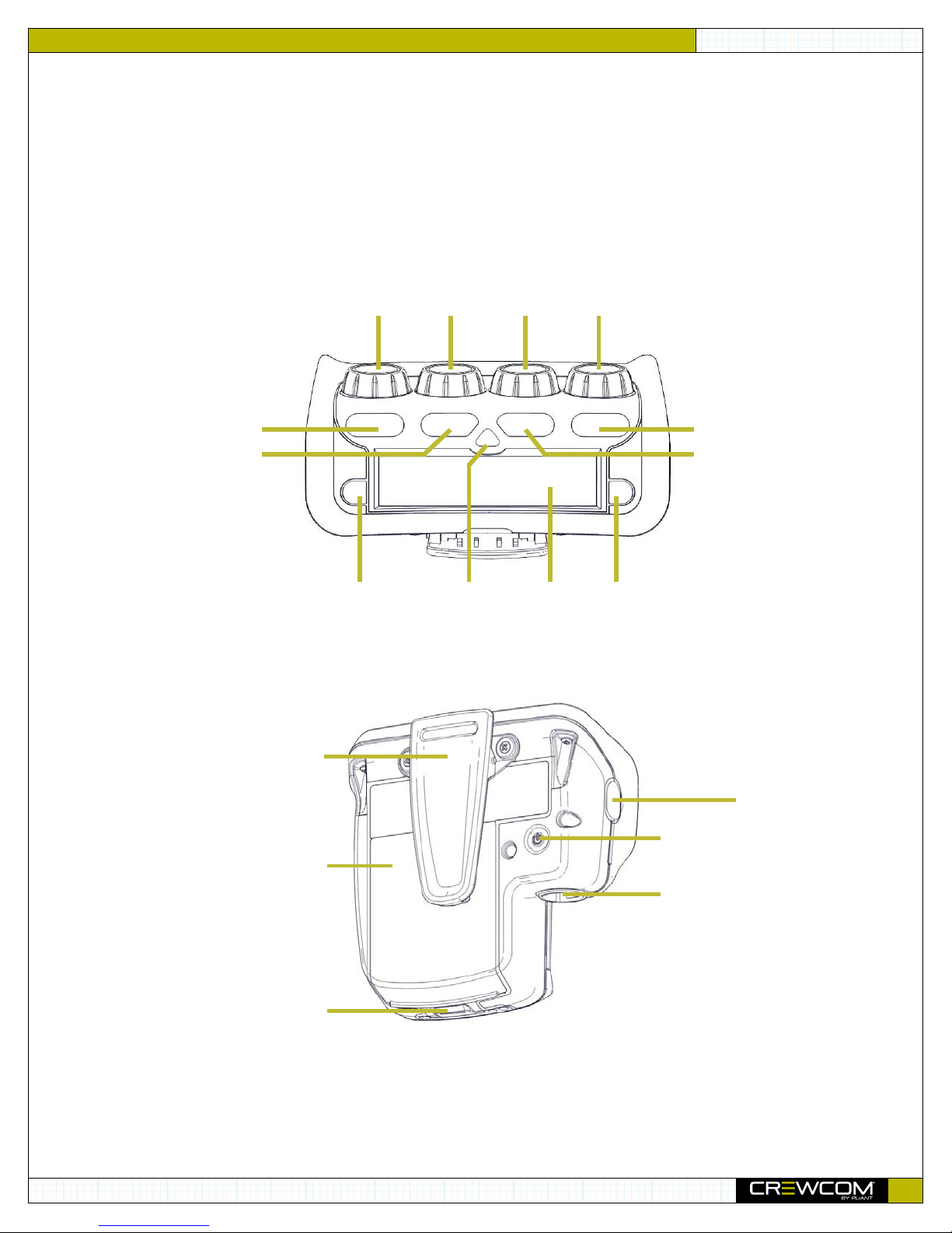
Talk A
Talk B
Talk D
Talk C
Function 2 (F2)LCDMenuFunction 1 (F1)
Vol A Vol B Vol C Vol D
RADIO PACK MANUAL
Product Overview
The CrewCom Radio Pack is available in a 4Vol (CRP-44) and a 2Vol (CRP-22) model and can be used with the CrewCom system
in highly-varying applications and environments. Each of these models are identical, other than the number of controls and their
related proles.
The following sections provide overviews of the different Radio Pack models’ controls and characteristics:
CRP-44 Model
Belt Clip
Battery
Compartment
Battery Door
Release
Figure 2: Radio Pack Rear View (All RP models have identical rear views.)
Figure 1: CRP-44 Top View
USB (Micro B)
Connection
On/Off
Headset
Connector
9

Product Overview
Volume Knobs/ISO Buttons
The volume controls adjust the listening volume of the connected headset for each of their respective assigned conferences. Turning
the volume control clockwise increases the audio level, while turning the control counter-clockwise decreases the level.
When pressed, the volume knobs also serve as ISO buttons to allow selective talk around. ISO means that selected users can have
an isolated conversation with other ISO-enabled users. While an ISO conversation occurs, the main conference audio can still be
heard. ISO must be separately enabled on both the Conference and each desired Prole from CrewWare.
Four volume knobs are available on the CRP-44 Radio Pack, and in CrewWare, they are named A, B, C, and D from left to right with
the knobs facing away from you.
Talk Buttons
The talk buttons enable or disable the microphone for each of their respective assigned conferences. Talk buttons can be set (from
the RP’s Prole) to function with a “Latch” or a “Momentary” press or they can be “Always On” or “Disabled.” When set to
“Disabled,” the Talk button has no function and allows for a listen-only conference on that pack.
In addition, CrewCom uses an intelligent latching method for talk buttons. When set to “Latch,” one short press will latch the talk
on; however, pressing and holding the talk button will cause the button to act as a momentary switch.
Four talk buttons are available on the CRP-44 Radio Pack, and in CrewWare, they are named A, B, C, and D from left to right with
the knobs facing away from you.
RADIO PACK MANUAL
Function Buttons (F1/F2)
The left (F1) and right (F2) function buttons can be programmed to assign a variety of functions such as Call, Stage Announce, and
GPO Relays. Each function button’s operation is set in the Radio Pack’s prole, which can be customized via CrewWare. Every Radio
Pack model has two function buttons. While in the menu, one short press of F1 returns you to the previous menu without saving any
changes.
Menu Button
The Menu button provides multiple functions such as access to menu options or toggling between the home operating screen and
the secondary operating screen.
• Short Press – Cycles the Radio Pack LCD from the Home Operating screen to the Secondary Operating screen and vice
versa.
• Long Press – Accesses the menu options of the Radio Pack to view Pack/System Information and make setting
adjustments. (The user may also continue to hold the button after the menu appears to display the
• Escape – While in the menu, one short press returns you to the previous menu without saving any changes.
LCD
Display for viewing real-time status of the Radio Pack, navigating menu options, and making subsequent setting adjustments.
Belt Clip
Secure and sturdy belt clip enables Radio Pack wearing via belt or lanyard.
Tech Info
menu.)
Battery Compartment Door
Secures and protects the Radio Pack’s Lithium-Polymer battery or 3 AA batteries. When the Battery Door Release is pressed, the
battery door will release and detach from the Radio Pack.
Battery Door Release
Pressing the release opens the Radio Pack’s battery compartment door.
10

Product Overview
Function 2 (F2)LCDMenuFunction 1 (F1)
Talk A Talk B
Vol A Vol B
USB (Micro B) Connection
This USB connection is for connecting a Radio Pack to a Control Unit for pairing. The Radio Pack may also be connected to a PC for
rmware updates via CrewWare. See the CrewWare Manual for more information on updating rmware.
On/Off Button
The On/Off button powers the Radio Pack on and off when pressed for 3 seconds.
4-Pin Male XLR Headset Connector
Headset connector is a 4-PIN male XLR connection. A compatible headset must be provided by the user. See page 23 for
connection pinout and headset wiring information.
RADIO PACK MANUAL
CRP-22 Model
The CRP-22 model has the same controls and functions as the CRP-44, with two exceptions: the talk buttons and volume knobs.
Figure 3: CRP-22 Top View
Volume Knobs/ISO Buttons
Two volume knobs are available on the CRP-22 Radio Pack, and they are named A and B from left to right in CrewWare.
Talk Buttons
Two talk buttons are available on the CRP-22 Radio Pack, and they are named A and B from left to right in CrewWare.
11

Product Overview
Connected RTPack Name Assigned
Prole
Radio Signal
Strength Value
Remaining Battery Time
RADIO PACK MANUAL
Radio Pack LCD Display
Home Operating Screen
Serves as the main operating screen to the user and displays the status of the Radio Pack as well as talk, volume, and function
assignments.
Conf. A Conf. B Conf. C
(Inverted color
indicates engaged
talk button)
Pack Name
F1 Assignment
Conf. D
Volume Level
(Displays when adjusted)
F2 Assignment
Battery LevelRadio Signal
Strength Indicator
Link Quality
Figure 4: RP Home Operating Screen Overview
Note: The Link Quality Indicator (LQ) provides a diagnostic measurement of actual packet transmission from Radio
Pack to RT and vice versa. The outlined LQ represents the Radio Transceiver’s LQ. For more information on
LQ, see “Understanding Link Quality” on page 16.
Secondary Operating Screen
Serves as a secondary operating screen to the user and displays additional information about the status of the Radio Pack. Short
press the Menu button once to toggle between the Home and Secondary screens. After 60 seconds, the screen will timeout and
revert back to the Home screen.
Figure 5: RP Secondary Operating Screen Overview
Note: Radio Signal Strength Indicator (RSSI) Value displays the actual value of the RSSI in dBm.
12

Product Overview
Radio Pack Battery System
Radio Packs are powered with (1) Lithium-Polymer rechargeable battery for greater
than 10 hours (2.4GHz) or 9 hours (900MHz), or they may be powered with (3) AA
batteries for approximately 5 hours (2.4GHz) or 4.5 hours (900MHz).
The batteries can be charged either inside the Radio Pack with an external power
supply or by using the 5-bay battery charger. The batteries require approximately 3
hours to charge from empty. Take care to insert the battery with the contacts facing
down into the Radio Pack and oriented such that the contacts on the battery will lineup with the contacts inside the Radio Pack battery compartment. See page 14 for
more information about installing RP batteries. See page 14 for more information
about charging RP batteries.
The Radio Pack may also be powered by three (3) AA batteries. Pliant recommends
that only major brand, standard batteries should be used for maximum reliability and
effectiveness. The user should expect approximately 5 hours (2.4GHz) or 4.5 hours
(900MHz) of operation using new AA batteries.
RADIO PACK MANUAL
There are several considerations the user should take into account when using AA
batteries. The RP’s battery level and remaining battery time indicators only reect battery
life for lithium-polymer batteries; therefore, those screen options will not be used when
AA batteries are in use. In cold weather, AA batteries do not release their stored energy completely, so the result is a dramatic
reduction in operation time. It would not be uncommon to have an AA battery only last 50% of its original life when used in very
cold situations.
CAUTION:
If using AA batteries instead of lithium-polymer batteries, remove the AA batteries from the
Radio Pack when not in use to avoid potential damage from leaking battery acid that can
sometimes occur in these types of batteries.
Figure 6: 5-Bay Battery Charger
13

Setup and Installation
RADIO PACK MANUAL
Setup and Installation
Installing a Radio Pack Battery
Before powering on an RP, install its battery by doing the following:
1. Hold the RP at about a 45 degree angle, pointing the bottom end down. Then, depress the RP’s belt clip and hold it.
2. Press the battery-release button on the bottom of the RP and pry open the battery door. Remove the door.
3. While still holding the RP at an angle and depressing the belt clip, install a fully charged Lithium-Polymer rechargeable
battery or three AA batteries in the RP.
4. Place the battery door back on the RP, making sure to align its tab and secure the door by pressing until it clicks.
5. Turn on the RP by pressing and holding the Power button on the back for three seconds.
Note: The RP will not communicate unless it has been paired to a Control Unit; if it has not been paired it will
indicate “No Pairing Information Available” on its display. In addition, the RP will not communicate if
its CU and RTs are not yet online. Pliant recommends powering on CUs and RTs rst before powering on RPs.
Figure 7: RP Battery Compartment Door
Charging a Radio Pack
To charge the Radio Pack (RP), connect the plug-in battery charger (included with the RP) to a standard wall outlet and to the
Micro-USB connector on the RP. The connector is located under the rubberized access cover on the side of the RP. The battery may
also be charged inside the RP via the USB port of a computer.
Pliant also offers a 5-bay battery charger (PBT-5BAY-01) for charging up to ve (5) Pliant lithium-polymer batteries.
CAUTION:
If charger(s) overheat, they need to be moved to a cooler area to charge batteries properly.
As a lithium-polymer battery safety mechanism, the battery chargers include a safety circuit,
which prevents charging of batteries if the ambient temperature is too hot.
Figure 8: RP Battery Removal/Insertion
14

Setup and Installation
RADIO PACK MANUAL
Pairing a Radio Pack (to a Control Unit)
CrewCom Radio Packs (RP) must be paired to a Control Unit (CU) before they can operate on any CrewCom system. Once RPs are
paired to a CU, this process does not need to be done again unless the RP is being paired to a new or different CU (for example,
after a replacement is made for repairs). A maximum of 255 RPs can be paired to a single CU; however only 18 of those RPs can be
active at one time. If having more active RPs is applicable, you will need another CU. The limit for active communicating RPs is 72 on
four CUs.
A Radio Pack (RP) may be paired without installing a battery, if applicable. The CU will provide power to the RP during the setup
process. If no battery is installed, the RP will shut off as soon as it is disconnected from the CU. During the pairing process, do not
disconnect the RP until you are instructed to do so. To pair your RP, use the following steps:
1. Connect an RT to the selected CU. Power on the CU.
2. Wait about two minutes for the conguration le to load on the system. The CU will display a “CCF Loaded” message
and a conguration le summary during the load process--wait until this message has cleared from the bottom CU screen
before taking further action. Once the message times out, the home screen will display on the front of the CU.
3. Ensure the selected RP is powered OFF.
4. Connect a USB-to-Micro-USB cable from the CU to the device (micro end goes into the RP’s USB port beneath its rubber
port cover). The RP will power on by itself.
5. Follow the prompts that display on the RP LCD.
a. Your RP must match the system rmware version. The system will check that the RP rmware matches. If it does not,
disconnect the RP from the CU and connect it to your PC to update rmware from CrewWare. For more information
on this procedure, see the
b. If the rmware matches, the pairing process will automatically begin and should take about 30 seconds. Do not
disconnect during this process.
6. Once pairing is initiated, you will be prompted via the RP’s LCD to select a Prole to apply to your RP (only Proles
compatible with the RP model will be available); use the RP function button and volume knobs to navigate and select
your choice from the list of available options.
Note: Default Proles are available as part of the Control Unit’s default CrewCom Conguration File.
For more information on default Prole settings, see “CrewCom Conguration File Defaults” on
page 8 of this manual. For more information on creating custom Proles, see the CrewWare
Operating Manual.
7. Wait for the Prole to load. The RP LCD will display a “Pairing Complete” message when the prole is nished
loading.
8. Disconnect the USB cable from the device. The RP will power off automatically when disconnected.
9. Power on the RP and wait for it to log in to the system. The initial login may take up to 1.5 minutes. When an RP is
logged in, its RSSI indicator will display on its primary screen.
CrewWare Manual
.
10. Verify that the RP paired correctly and is displayed on the CU LCD and CrewWare (if connected).
Note: RPs can be paired while CrewWare is ofine or while it is in “Live” mode. When in Live mode, you
should see the RPs appear in CrewWare’s real-time pack display as they are paired. Ofine mode will
not display newly paired RPs until the system is “Live.”
11. The RP is ready for use. Repeat steps 3–10 until every RP is paired.
15

Operation
RP to RT
RT to RP
RADIO PACK MANUAL
Operation
Much of a Radio Pack’s functionality is driven by the assigned Prole. However, there are certain device and user settings that can
be congured depending on a user’s access rights given to them by the system administrator. The following instructions will help you
operate and customize your device.
Many of the following instructions apply to the Radio Pack’s menu options. Access to certain menus and setting adjustments are
determined by the system’s access rights; see the
information about access rights.
Understanding Link Quality
The Link Quality (LQ) is a numeric value that provides a real-time metric on the quality of communication between the Radio
Transceiver and the Radio Pack. The LQ serves as a diagnostic tool for proper system operation and troubleshooting Radio Packs.
• The LQ value represents the number of successful audio packets
of the last 100 transmissions—99 being the most, 0 being the
least.
• With CrewCom, the receiving LQ signal is reported for both the
Radio Transceiver and Radio Pack. The Radio Pack’s on-screen
LQ indicator with the box around it is the Transceiver’s LQ from
the RP. If this LQ is lower than you typically experience in normal
operation, then it is an indication that you may have an issue
related to interference, the transceiver, or a cable connection. If
only the RP’s LQ is low, it could be an indication that you may
have an issue related to interference or the Radio Pack.
Control Unit Operating Manual
or the
CrewWare Operating Manual
Link Quality
Figure 9: RP Primary Screen LQ Indicator
for more
Link Quality
• What should the LQ value be during operation? — The LQ will not remain at an exact value during system operation.
Depending on what degree of outside interference or attenuation (blocking) is present, the LQ will uctuate during
normal operation. Fluctuations in LQ can and will span a wide range of values. The lower the LQ, the poorer the audio
quality will be during operation. During start-up, within adequate range and no outside inuences present, the LQ should
display “99” which is the highest LQ value a Radio Pack or Radio Transceiver can have.
• What if the LQ on a single Radio Pack is below “99” at start-up? — This depends on where the Radio Pack is located at
start-up, but if the other Radio Packs on the same Radio Transceiver are at “99” this is a good indication that an isolated
radio issue exists within that Radio Pack. If the LQ value has dropped considerably lower or if that unit is experiencing
poor audio quality, it may require service.
Pack Information
For a quick snapshot of the Radio Pack’s device and user settings, Press the RP Menu button for 2 seconds and use the far-right
volume knob to scroll and select
knob to page through the following information:
• Radio Pack Model Number
• Prole Name
• Mic Type
• Mic Gain
• Noise Gate
Pack Info
from the Main Menu. From this screen, users can use the F2 button or far-right volume
• Radio Pack Firmware Version
• RT Name (if currently logged in)
• LCD Backlight Contrast
• LCD Backlight Brightness
• LCD Backlight Timeout
• Sidetone
• Talk Tones
• Radio Pack Serial Number
• Volume Minimum
• Volume Maximum
16

Operation
RADIO PACK MANUAL
Device Settings
The following settings and processes can be found in the Radio Pack’s menu under
managed via the Control Unit menu or by using CrewWare; refer to the CrewWare Operating Manual for more information.
Selecting Radio Pack Prole
Each time a Radio Pack is paired to a CrewCom Control Unit, you will be prompted to select a Prole to assign to that Pack. Radio
Pack Proles must match the type of Radio Pack, and thus only Proles specic to the Radio Pack model being paired or used will
appear in the available list. In addition, only default proles will be available until new (custom) proles have been created using
CrewWare. Default prole settings are detailed in“CrewCom Conguration File Defaults” on page 8 of this manual. For more
information on creating custom proles, see the
A Radio Pack stores only the prole currently assigned to it. To change a Radio Pack’s assigned prole from the RP, use the
following steps:
CrewWare Operating Manual
Device Settings
.
. These settings can also be
1. Press and hold the RP Menu button for 2 seconds; then, use the far-right volume knob to scroll and select
Settings
2. Scroll and select
3. Scroll to the desired prole.
4. Press F2 (
settings. Upon saving the new prole, the RP will be updated with its most up-to-date prole settings. The RP will be
operational with its new prole and settings when connected to a live system.
NOTE: You can also change an RP’s assigned Prole from CrewWare and from the CU menu. See those manuals for
. Press F2 (
Pack Proles
SAVE
). A prompt will display, asking you to conrm your selection to overwrite user-level settings with prole
more information.
ENT
).
. Press F2 (
ENT
) to view a list of available proles.
Figure 10: Prole Selection Screen
Editing Radio Pack Name
Radio Packs can be given a 16-character long name and an 8-character short name using the following steps:
1. Press and hold the RP Menu button for 2 seconds; then, use the far-right volume knob to scroll and select
Settings
. Press F2 (
ENT
).
Device
Device
2. Scroll and select
3. Scroll to select either
4. Use the far left and far right talk buttons to navigate left or right through the characters of the name. Use the far-right
volume knob to navigate up and down to change each character value.
5. Press F2 (
Pack Name
Short Name
SAVE
). Once saved, the screen will return to the previous menu.
. Press F2 (
ENT
or
Long Name
) to view a list of name options.
and press F2 (
Figure 11: Pack Name Edit Mode
ENT
) to enter edit mode.
17

Operation
RADIO PACK MANUAL
Customizing Battery Alert
This sub-menu allows you to adjust the type of battery alert the Pack will give when reporting low lithium-polymer battery life. An
audible alert sounds a tone in the connected headset when the battery life is low. A vibrate alert briey vibrates the RP. To change
your battery alert, do the following:
1. Press and hold the RP Menu button for 2 seconds; then, use the far-right volume knob to scroll and select
Settings
2. Scroll and select
. Press F2 (
Battery Alert
ENT
).
. The current alert selection will be displayed on the right-hand side. Press F2 (
Device
ENT
) to
view a list of available alert options.
Figure 12: Customizing Battery Alert
3. Scroll and select from the following:
4. Press F2 (
SAVE
). Once saved, the screen will return to the previous menu.
Audible, Vibrate, Both
, or
Off
.
Note: The RP Battery Alert only reects battery life for lithium-polymer batteries; therefore, this alert will not be
used when AA batteries are in use.
Adjusting LCD Display Settings
The Radio Pack’s LCD has adjustable settings such as Contrast, Brightness, and Backlight Time Out. The following settings can be
found in the Radio Pack’s menu under
Device Settings
then
Display Options
.
• Contrast – Allows adjustment to the LCD’s contrast; use the volume knobs to increase or decrease the level of contrast.
Select an option in the range from
• Backlight Brightness – Allows adjustment to the LCD’s brightness; select from
level.
• Backlight Time Out – Enables users to set the amount of time the LCD’s backlight will stay lit after engaging the Radio
Pack’s interface. Select from
Disabled, 3, 10
0–10.
Figure 13: RP Display Options
, or 30 seconds.
High, Med, Low
, or
Off
for brightness
18

Operation
RADIO PACK MANUAL
User Settings
The following settings and processes can be found in the Radio Pack’s menu under
managed via the Control Unit’s menu or by using CrewWare; refer to the CrewWare Operating Manual for more information.
Selecting Headset Mic Type
Select from
the RP for a microphone to be detected. If you select a mic type that does not match the detected type of the connected mic, you
will be prompted to accept the exception.
Auto-Detect, Dynamic
, or
Electret
mic type. If selecting
Figure 14: Selecting Mic Type
Auto-Detect
Adjusting Mic Gain
When the Mic Gain is set too high, it is possible to induce feedback or echo. When set too low, words can be clipped by the low
level noise gate, or may sound too quiet to other listeners. Different models of headsets will require widely varying mic gain settings.
User Settings
, you must rst have a headset connected to
. These settings can also be
1. Press and hold the RP Menu button for 2 seconds; then, use the far-right volume knob to scroll and select
Settings
2. Scroll and select
3. Scroll and select either
side. Press F2 (
4. Use the far-right volume knob to increase or decrease the Mic Gain level. For dynamic microphones, select from within a
range of +6 to +35 dB. For electret microphones, select from within a range of -12 to +17 dB.
5. Press F2 (
. Press F2 (
SAVE
ENT
).
Mic Gain
ENT
) to view a list of available setting options.
). Once saved, the screen will return to the previous menu.
. Press F2 (
Dynamic Gain
ENT
).
or
Electret Gain
Figure 15: Adjusting Mic Gain
. The current mic gain setting will be displayed on the right-hand
User
19

Operation
RADIO PACK MANUAL
Adjusting Noise Gate
The noise gate is used to set the minimum audio threshold necessary to allow audio to pass from the headset microphone through
to the rest of the system. When the audio level from the microphone is below this threshold, the gate is closed and the audio is
muted. When the audio level from the microphone is above this threshold, the gate is open and audio passes. Setting the noise
gate threshold too high can cause the beginning of words to be cut off or make the audio sound choppy, so Pliant recommends
setting the noise gate as low as possible.
Adjust your Radio Pack noise gate threshold using these steps:
1. Press and hold the RP Menu button for 2 seconds; then, use the far-right volume knob to scroll and select
Settings
2. Scroll and select
. Press F2 (
Noise Gate
ENT
).
. The current noise gate setting will be displayed on the right-hand side. Press F2 (
User
ENT
) to
view a list of available setting options.
Figure 16: Adjusting Noise Gate
3. Scroll to select from the range of options:
Very High -48, High -57, Medium -66, Low -75
, and
Off
. These options
correspond to a range of levels from -48 dB (very high) to -∞ (off).
4. Press F2 (
SAVE
). Once saved, the screen will return to the previous menu.
Adjusting Sidetone
Speak into the headset microphone at a typical speaking level and adjust the sound of your own voice in your headset. Adjust your
Radio Pack sidetone using these steps:
Note: It is important to set this sidetone as low as comfortable for the user to insure best performance.
Setting the sidetone too high will cause the user to speak softly and cause poor audio performance.
1. Press and hold the RP Menu button for 2 seconds; then, use the far-right volume knob to scroll and select
Settings
2. Scroll and select
. Press F2 (
Sidetone
ENT
).
. The current sidetone setting will be displayed on the right-hand side. Press F2 (
a list of available setting options.
Figure 17: Adjusting Sidetone
3. Scroll to select from the range of options:
Very High 0, High -6, Medium -12, Low -18
, and
Very Low -24
options correspond to a range of levels from 0 dB to -24 dB.
4. Press F2 (
SAVE
). Once saved, the screen will return to the previous menu.
User
ENT
) to view
. These
20

Operation
RADIO PACK MANUAL
Adjusting Volume Limit
The Radio Pack is capable of adjusting a minimum and maximum volume limit for each conference assignment. Adjust your Radio
Pack volume limit using these steps:
Figure 18: Adjusting Volume Limits
Minimum Volume
1. Press and hold the RP Menu button for 2 seconds; then, use the far-right volume knob to scroll and select
Press F2 (
ENT
).
User Settings
.
2. Scroll and select
side. Press F2 (
ENT
Min Volume
) to view a list of available setting options.
. The current minimum settings for each volume knob will be displayed on the right-hand
3. Turn each corresponding volume knob to increase or decrease the volume level to your desired limit within a range of 0 to
19 with 0 being OFF. This range corresponds to a range from OFF (-57 dB) to +3 dB.
SAVE
4. Press F2 (
). Once saved, the screen will return to the previous menu.
Maximum Volume
1. Press and hold the RP Menu button for 2 seconds; then, use the far-right volume knob to scroll and select
Press F2 (
2. Scroll and select
side. Press F2 (
ENT
).
ENT
Max Volume
. The current minimum settings for each volume knob will be displayed on the right-hand
) to view a list of available setting options.
User Settings
3. Turn each corresponding volume knob to increase or decrease the volume level to your desired limit within a range of 1 to
20. This range corresponds to a range from -53 dB to +6 dB.
SAVE
4. Press F2 (
). Once saved, the screen will return to the previous menu.
Adjusting Talk Tones
Enabling Talk Tones gives the user audible feedback when a talk button is pressed to talk on a conference. Adjust your Radio Pack
talk tones using these steps:
1. Press and hold the RP Menu button for 2 seconds; then, use the far-right volume knob to scroll and select
Press F2 (
ENT
).
User Settings
.
.
2. Scroll and select
Talk Tones
. The talk tones setting will be displayed on the right-hand side. Press F2 (
of available setting options.
On
or
3. Scroll to select either
SAVE
4. Press F2 (
). Once saved, the screen will return to the previous menu.
Off
ENT
) to view a list
Figure 19: Adjusting Talk Tones
.
21

Operation
RADIO PACK MANUAL
Tech Menu
The Tech Menu is typically for use by system administrators to review or monitor system level security settings or diagnostics. The
following settings and processes can be found in the Radio Pack’s menu under
Restoring Factory Defaults
Users can choose to restore factory defaults from the device or system:
Tech Menu
.
1. Press and hold the RP Menu button for 2 seconds; then, use the far-right volume knob to scroll and select
Press F2 (
2. Scroll and select
3. Scroll and select
4. Conrm your selection by selecting either
Table 2 lists the settings that are affected when restoring RP factory defaults.
Table 2: Radio Pack Factory Default Settings
Radio Pack Setting Radio Pack Default
Pack Name (Long) ESN#
Pack Name (Short) ESN#
Battery Alert Both
Contrast 7
Backlight Brightness High
Backlight Time Out 30 seconds
Mic Type Auto Detect X
Mic Gain (Dynamic) 6 (+23 dB) X
Mic Gain (Electret) 3 (-4 dB) X
Noise Gate Low (-75 dB) X
Sidetone Med (-12 dB) X
Minimum Volume (all knobs) 0 (off) X
Maximum Volume (all knobs) 20 (+6 dB) X
Talk Tones Off X
User Rights Admin
ENT
).
Factory Defaults
Restore Defaults
press F2 (
and press F2 (
Yes
ENT
or No.
) to enter view reset options.
ENT
).
Reset by
“Restore
Defaults”
Tech Menu
.
22

Operation
Radio Pack Menu
The following menu tree displays all of the Radio Pack’s menu options and settings.
Pack Info Device Settings User Settings Tech Menu
RADIO PACK MANUAL
Page 1
Model
Pro le
Mode
Serial Number
Firmware Revision
Transceiver
Page 2
Mic Type
Mic Gain
Noise Gate
Contrast
Backlight Brightness
Backlight Time Out
Page 3
Side Tone
Talk Tones
Volume Min
Volume Max
Pack Pro les
Pack Name
Short Name
Long Name
Battery Alert
Display Options
Contrast
Backlight Brightness
Backlight Timeout
Mic Type
Auto Detect
Dynamic
Electret
Mic Gain
Dynamic Mic Detected:
0 (+6dB) to 10 (+35 dB)
Electret Mic Detected:
0 (-12 dB) to 10 (+17 dB)
Noise Gate
Very High -48 dB
High -57 dB
Medium -66 dB
Low -75 dB
Off
Sidetone
Very High -0dB
High -6 dB
Medium -12 dB
Low -18 dB
Very Low -24 dB
Min Volume
0 (-57 dB) to 19 (+3 dB)
Max Volume
1 (-53 dB) to 20 (+6 dB)
Factory Defaults
Restore Defaults
Headset Connector Pinout and Wiring
Table 3: Local Headset Connection Wiring
XLR Pin # Description
Pin 1 Mic −
Pin 2 Mic +
Pin 3 Speaker −
Pin 4 Speaker +
2
Male
Talk Tones
On
Off
See the SmartBoom PRO and SmartBoom LITE
datasheets for the pin wiring information for Pliant’s
SmartBoom headsets.
41
3
23

Product Specifications
RADIO PACK MANUAL
Product Specications
Table 4: Radio Pack Specications*
Specication CRP-22-900/
CRP-22-900AN**
RF Frequency (MHz) 902–928 MHz
RF Scheme FHSS with TDMA
Effective Radiated Power
Receiver Sensitivity -100 dBm at 10
Radio Certication FFCCID: HSW-CCT900 and
Transmission Range
Audio Dynamic Range Greater than 90 dB
Audio Frequency Response 150 Hz–7 kHz
Conferences
Simultaneous Listen Paths
Volume Knobs
Talk Buttons
Headset Connector
Microphone Type Auto-Detect or Manual Select; Dynamic or Electret
LCD Display
Antenna (2) 2dBi Dipole
Battery Life, Rechargeable
Lithium-Polymer
Charging Power Supply Micro USB; 6W AC wall adapter
Charge Time for LithiumPolymer Battery
Optional Power
Battery Life, AA Batteries
Dimensions (L x W x H) 11.43 cm × 11.61 cm × 5.87 cm (4.50 in. × 4.57 in. × 2.31 in.)
Weight (with Lithium-Polymer
battery)
Material Polycarbonate substrate with thermoplastic elastomer overmold
Operating Environment -20° to 50° C (-4° to 122° F); 10% to 90% Humidity.
Maximum Altitude 2,000 m (6,562 ft.)
RoHS Compliant
IP Rating
200 m (approx. 650 ft.) under typical conditions; 600
m (approx. 1950 ft.) line of sight (Note: Functional
range depends on many variables, including RF signal
absorption, reection, and external interference.)
2 4 2
True Dual Listen True Quad Listen True Dual Listen
2 4 2
2 4 2
Greater than 9 hours Greater than 10 hours
Approximately 4.5 hours Approximately 5 hours
CRP-44-900/
CRP-44-900AN**
(915–928 MHz)**
400 mW (+26 dBm) 100 mW (+20 dBm)
IC: 4492A-CCT900
4-pin male XLR
280 × 64 resolution
Under 3 hours
3 Standard AA batteries
369 g (13 oz.)
RP Power Supply is 0 to 40° C (32° to 104° F).
CRP-22-2400/
CRP-22-2400CE***
-5
BER
FFCCID: HSW-CCT24 and
150 m (approx. 500 ft.) under typical conditions;
450 m (approx. 1500 ft.) line of sight (Note:
Functional range depends on many variables,
including RF signal absorption, reection, and
external interference.)
Yes
IP-65
CRP-44-2400/
CRP-44-2400CE***
2400–2483 MHz
IC: 4492A-CCT24
4
True Quad Listen
4
4
*Notice About Specications: While Pliant makes every attempt to maintain the accuracy of the information contained in this manual, this information is subject to change
without notice, and published device/system functions and features are subject to rmware version. Please check our website for the latest system specications and
certications. 900MHz products only available in North America, Australia, and New Zealand.
**CRP-22-900AN and CRP-44-900AN (Oceania) models are approved for use in Australia and New Zealand and operate within the 915–928 MHz frequency range.
***CRP-44-2400CE and CRP-22-2400CE models meet the same specications and comply with ETSI standards (300.328 v1.8.1). Non-CE models are non-compliant with some
ETSI standards.
24

Product Specifications
RADIO PACK MANUAL
Product Support
Pliant offers technical support via phone and email from 07:00 to 19:00 Central Time (UTC−06:00), seven days per week.
1.844.475.4268 or +1.334.321.1160
technical.support@plianttechnologies.com
Visit www.plianttechnologies.com for product support, documentation, and live chat for help. (Live chat available 08:00 to 17:00
Central Time (UTC−06:00), Monday–Friday.)
Returning Equipment for Repair or Maintenance
All questions and/or requests for a Return Authorization Number should be directed to the Customer Service department
(customer.service@plianttechnologies.com). Do not return any equipment directly to the factory without rst obtaining a Return
Material Authorization (RMA) Number. Obtaining a Return Material Authorization Number will ensure that your equipment is
handled promptly.
All shipments of Pliant products should be made via UPS, or the best available shipper, prepaid and insured. The equipment should
be shipped in the original packing carton; if that is not available, use any suitable container that is rigid and of adequate size to
surround the equipment with at least four inches of shock-absorbing material. All shipments should be sent to the following address
and must include a Return Material Authorization Number:
Pliant Technologies Customer Service Department
Attn: Return Material Authorization #
205 Technology Parkway
Auburn, AL 36830-0500
25

Maintenance and Storage
RADIO PACK MANUAL
Maintenance and Storage
Cleaning
Generally, the CrewCom hardware should be cleaned only with a dry cloth. A soft cloth with rubbing alcohol may be used to wipe
the devices if needed, but you should avoid using rubbing alcohol on plastic components. Never spray solvents or chemicals onto
the devices.
All electronic devices can be susceptible to particulate contamination. If yours are exposed to an extremely dusty environment,
contact Pliant’s Customer Service for internal cleaning.
Temperature and Humidity
CrewCom components are designed to be very durable and can tolerate a wide range of environmental conditions; however, you
should take all necessary precautions to keep your system devices safe, dry, and out of extreme conditions.
The Radio Transceiver is weather-resistant, including gaskets intended to prevent moisture entry from the top and sides. The Cat 5e
cable connection on the bottom is not water tight. If it is to be used in an outdoor environment, protect the RT with a protective
enclosure that will not interfere with the radio signals.
The Radio Packs are designed to work wherever people work. While the Radio Pack design is weather-resistant, Radio Packs should
not be submerged in liquids unnecessarily. Protect the battery compartment from water when changing batteries. The battery
compartment offers a route to the electronic circuitry.
Storage of your Lithium-Polymer Batteries
When stored, a battery gradually loses its overall charge time due to internal self-discharge, which may reduce its overall power.
If storing batteries for two or more weeks, Pliant Technologies highly recommends storing them at a 40-50% charge level, which
generally minimizes any permanent power capacity loss.
Unused lithium-polymer batteries may enter into a deep discharge state due to internal self-discharge. Once a battery has gone
into deep discharge, its onboard circuit protections inhibit the charger from initiating the charge cycle. If a battery does not accept a
charge and the LED displays red in the charger, the battery may be in deep discharge. An attempt to revive the battery can be made
by repeatedly inserting and removing it several times from the 5-Bay Charger (PBT-5BAY-01).
Ambient temperature affects the rate at which lithium-polymer batteries degrade. Batteries also degrade and lose overall power
capacity if stored (or used) at higher temperatures.
Proper Disposal of Old Lithium-Polymer Batteries
Batteries that appear swollen, deformed, or damaged, or that do not t properly should never be used. Properly dispose of any
batteries in this condition in accordance with the instructions provided by your local authorities. For more information and local
drop-off sites, visit http://www.call2recycle.org/.
Battery Shipping Regulations
Rechargeable lithium-polymer batteries are subject to special U.S. and International regulations, particularly regarding
transportation. The guidelines detailed in Pliant’s Lithium-Polymer Battery Shipping Guidelines document comply with updated
International Air Transport Association (IATA), International Civil Aviation Organization (ICAO), and U.S. Department of
Transportation (DOT) Dangerous and Hazardous Goods regulations.
When shipping equipment to Pliant that includes batteries, it is the shipper’s responsibility to ensure that batteries are properly
packaged, labeled, and shipped according to local and international guidelines. “Shipper” is dened as the person or entity placing
the equipment in the package and offering it to the carrier.
26

License Information
RADIO PACK MANUAL
License Information
Warning: Changes or modications to this device not expressly approved by Pliant could void the user’s authority
to operate the equipment.
1. FCC Notices
1.1. This device complies with Part 15 of the FCC Rules. Operation is subject to the following two conditions: (1)
This device may not cause harmful interference, and (2) this device must accept any interference that may cause
undesired operation.
1.2. This equipment has been tested and found to comply with the limits for a Class A digital device, pursuant to part
15 of the FCC rules. These limits are designed to provide reasonable protection against harmful interference when
the equipment is operated in a commercial environment. This equipment generates, uses, and can radiate radio
frequency energy and, if not installed and used in accordance with the instruction manual, may cause harmful
interference to radio communications. Operation of this equipment in a residential area is likely to cause harmful
interference in which case the user will be required to correct the interference at his own expense.
2. Canada, Industry Canada (IC) Notices
2.1. This Class A digital apparatus complies with Canadian ICES-003.
Cet appareil numerique de la classe A est conforme a la norme NMB-003 du Canada.
2.2. Under Industry Canada regulations, this radio transmitter may only operate using an antenna of a type and
maximum (or lesser) gain approved for the transmitter by Industry Canada. To reduce potential radio interference
to other users, the antenna type and its gain should be so chosen that the equivalent isotropically radiated power
(e.i.r.p.) is not more than that necessary for successful communication.
Conformément à la réglementation d’Industrie Canada, le présent émetteur radio peut fonctionner avec une
antenne d’un type et d’un gain maximal (ou inférieur) approuvé pour l’émetteur par Industrie Canada. Dans le
but de réduire les risques de brouillage radioélectrique à l’intention des autres utilisateurs, il faut choisir le type
d’antenne et son gain de sorte que la puissance isotrope rayonnée équivalente (p.i.r.e.) ne dépasse pas l’intensité
nécessaire à l’établissement d’une communication satisfaisante.
2.3. This device complies with Industry Canada licence-exempt RSS standard(s). Operation is subject to the following
two conditions: (1) this device may not cause interference, and (2) this device must accept any interference,
including interference that may cause undesired operation of the device.
Le présent appareil est conforme aux CNR d’Industrie Canada applicables aux appareils radio exempts de licence.
L’exploitation est autorisée aux deux conditions suivantes : (1) l’appareil ne doit pas produire de brouillage, et (2)
l’utilisateur de l’appareil doit accepter tout brouillage radioélectrique subi, même si le brouillage est susceptible
d’en compromettre le fonctionnement.
RF-Exposure Statement
CrewCom Radio Packs have been designed to be worn and used in close proximity to the human body—what the FCC calls a
“portable” use.
This equipment complies with FCC radiation exposure limits set forth for an uncontrolled environment. This equipment is in direct
contact with the body of the user under normal operating conditions. This transmitter must not be co-located or operating in
conjunction with any other antenna or transmitter.
27

License Information
CrewCom Compliance Numbers
Table 5: Radio Pack Compliance Model Numbers
Model Numbers Compliance Model No.
CRP-22-2400 RP2500
CRP-22-2400CE RP2500
CRP-22-900 RP2500
CRP-22-900AN RP2500
CRP-44-2400 RP2500
CRP-44-2400CE RP2500
CRP-44-900 RP2500
CRP-44-900AN RP2500
RADIO PACK MANUAL
28

Warranty Information
RADIO PACK MANUAL
Warranty Information
Limited Warranty
CrewCom products are warranted to be free from defects in materials and workmanship for a period of two years from the date of
sale to the end user, under the following conditions:
• First year of warranty included with purchase.
• Second year of warranty requires product registration on the Pliant website.
Tempest professional products will carry a two-year product warranty.
All accessories carry a one-year warranty.
The sole obligation of Pliant Technologies, LLC during the warranty period is to provide, without charge, parts and labor necessary to
remedy covered defects appearing in products returned prepaid to Pliant Technologies, LLC. This warranty does not cover any defect,
malfunction, or failure caused by circumstances beyond the control of Pliant Technologies, LLC, including but not limited to negligent
operation, abuse, accident, failure to follow instructions in the Operating Manual, defective or improper associated equipment,
attempts at modication and/or repair not authorized by Pliant Technologies, LLC, and shipping damage. Products with their serial
numbers removed or effaced are not covered by this warranty.
Pliant device IP ratings are dependent upon device design and assembly; therefore, unauthorized disassembly or device
modications may impair or negate the IP rating for the device, and therefore any associated damage or malfunction is not covered
under this warranty.
This limited warranty is the sole and exclusive express warranty given with respect to Pliant Technologies, LLC products. It is the
responsibility of the user to determine before purchase that this product is suitable for the user’s intended purpose. ANY AND
ALL IMPLIED WARRANTIES, INCLUDING THE IMPLIED WARRANTY OF MERCHANTABILITY, ARE LIMITED TO THE DURATION OF
THIS EXPRESS LIMITED WARRANTY. NEITHER PLIANT TECHNOLOGIES, LLC NOR ANY AUTHORIZED RESELLER WHO SELLS PLIANT
PROFESSIONAL INTERCOM PRODUCTS IS LIABLE FOR INCIDENTAL OR CONSEQUENTIAL DAMAGES OF ANY KIND.
Parts Limited Warranty
Replacement parts for Pliant Technologies, LLC products are warranted to be free from defects in materials and workmanship for
120 days from the date of sale to the end user.
This warranty does not cover any defect, malfunction, or failure caused by circumstances beyond the control of Pliant Technologies,
LLC, including but not limited to negligent operation, abuse, accident, failure to follow instructions in the Operating Manual,
defective or improper associated equipment, attempts at modication and/or repair not authorized by Pliant Technologies, LLC, and
shipping damage. Any damage done to a replacement part during its installation voids the warranty of the replacement part.
This limited warranty is the sole and exclusive express warranty given with respect to Pliant Technologies, LLC products. It is the
responsibility of the user to determine before purchase that this product is suitable for the user’s intended purpose. ANY AND
ALL IMPLIED WARRANTIES, INCLUDING THE IMPLIED WARRANTY OF MERCHANTABILITY, ARE LIMITED TO THE DURATION OF
THIS EXPRESS LIMITED WARRANTY. NEITHER PLIANT TECHNOLOGIES, LLC NOR ANY AUTHORIZED RESELLER WHO SELLS PLIANT
PROFESSIONAL INTERCOM PRODUCTS IS LIABLE FOR INCIDENTAL OR CONSEQUENTIAL DAMAGES OF ANY KIND.
29

Glossary
RADIO PACK MANUAL
Glossary
Audio Output: Outputs are created by mixing one or more audio entities. This could be for use at any headset connection or for
output to a wired connection.
Auto Detect: The CrewCom Radio Pack (RP) has the ability to automatically detect the type of microphone (dynamic or electret)
that is plugged into its headset connector. The Auto Detect setting is an option in the RP menu along with the manual selection of
dynamic or electret microphones.
Call Functions: Call signals may be initiated by entities across CrewNet. Each 2-Wire intercom port may be individually set to send
and receive a CrewCom-generated call signal to or from a connected wired intercom system by selecting ON to enable the Call
function. Turning the Call function off prevents the signal from leaving CrewCom via the respective port.
• Call: An RP Function button option. When enabled for wireless devices, a call signal will be sent to the RPs of each
conference whose Talk button is currently active on that individual RP. When enabled for external hardwired intercom
devices, a signal will be sent to any connected 2-wire devices associated with a conference whose Talk button is currently
active on that individual RP (as long as outbound call is enabled for the CU port associated to the conference). Call can
be enabled for both wireless and hardwired devices or limited to only one type.
• Call on Talk: An RP Talk button function. When enabled, a call signal will remain active while the Talk button is active.
This function is commonly used in applications where a two-way radio interface is connected.
• Call on Conference: An RP Function button option. When enabled for wireless devices, a call signal will be sent to the
RPs of the assigned conference, regardless of the associated Talk button’s status. When enabled for external hardwired
intercom devices, a signal will be sent to any connected 2-wire devices associated with that conference (as long as
outbound call is enabled for the associated CU port). Call on Conference can be enabled for both wireless and hardwired
devices or limited to only one type.
• Call Device: A CrewWare function that allows the user to call a specic Radio Pack from the Device Management tab of
CrewWare.
Conference: A grouping of audio entities. Wireless Radio Packs (or other CrewCom I/O) may be subscribed to one or more of 1024
available Conferences.
Control Unit (CCU-22 and CCU-44): A CrewCom device that is used to establish a CrewNet system and provides initial system
audio I/O. It is compatible with all levels of wireless Radio Packs.
CrewCom Conguration File (CCF): A le that stores all of the device setup and conguration parameters for a CrewCom system. These
les can be created, edited, saved, and recalled both online and ofine.
CrewNet: The digital proprietary network used to move audio and to control data, timing, and other functional signals used in
CrewCom.
CrewWare: Software tool developed to incorporate all the necessary mechanisms for facilitating graphically based system
construction and full system control, monitoring, and diagnosis.
Dynamic: A type of headset microphone used in professional headsets that do not require any type of external power for
operation. In general, dynamic microphones have a lower output than Electret microphones.
Electret: A type of headset microphone used in professional headsets that requires an external power source, such as from a
CrewCom Radio Pack. In general, electret microphones have a higher output than dynamic microphones.
Firmware: (As it relates to CrewCom.) The embedded code that exists in any CrewCom device. All of this embedded code, including
radio code, is upgradeable easily by the end user. It is required that all CrewCom devices operate on the same version of rmware.
30

Glossary
Frequency Band: The RF spectrum area that a device operates. For CrewCom, this is 900MHz (900–928 MHz) and 2.4GHz
(2400–2483 MHz).
GPO Relay: General Purpose Output. Electromechanical switches, which create a simple contact closures, used to trigger an event
or automation outside of the CrewCom system.
Hub: A device that provides routing and expansion capabilities to a CrewNet infrastructure allowing the connection of multiple
CrewCom devices.
ISM Bands: Industrial, Scientic, and Medical Bands. A part of the radio spectrum that can be used for any purpose without a
license in most countries.
ISO: Selected users can have an isolated conversation with other ISO-enabled users on a conference. While an ISO conversation
occurs, the main conference audio can still be heard. ISO must be separately enabled on both the Conference and each desired
Prole. From the Radio Pack, ISO is used by pressing and holding the corresponding Volume Knob.
Latch: A function (when enabled from the Radio Pack [RP] Prole) where one short press of the RP Talk button enables or disables
the microphone for each respective assigned conference until the button is pressed again. When in this mode, the Talk button has
an intelligent latching function: one short press will latch the talk on; however, pressing and holding the talk button will cause the
button to act as a momentary switch.
Link Quality: The percentage of successful audio packets sent/received (two different LQ numbers) between a wireless Radio Pack
and the Radio Transceiver.
RADIO PACK MANUAL
Mic Gain: Determines the headset microphone audio level being sent from the microphone pre amp. The user may experience
feedback or echo on their headset if the Mic Gain is set too high. If set too low, the noise gate may clip words or other listeners
may not hear the mic audio. Different models of headsets and different individual preferences require different Mic Gain settings.
Mic Kill: Each wired intercom port (2-Wire only) is capable of receiving a Mic Kill signal from a connected wired intercom system.
Each port is capable of sending a mic kill signal to connected RTS and AudioCom systems. The Mic Kill signal is passed through to
any Conference associated with the intercom port where the signal came through. Turning the Mic Kill signal off prevents external
Mic Kill signals from entering or leaving CrewCom via the respective port; however, Mic Kill signals may continue to be generated
and transmitted by entities across CrewNet. CrewCom does not send Mic Kill signals to Clear-Com 2-Wire systems.
Momentary:
A function (when enabled from the Radio Pack [RP] Prole) where holding the RP Talk button down enables the microphone
for each respective assigned conference until the switch is released.
Noise Gate: Used to set the minimum audio threshold necessary to allow audio to pass from the headset microphone through the
rest of the system.
Operating Mode: Denes the relationship and operating parameters for Radio Packs (RPs) and Radio Transceivers (RTs). A
selection can be made from either Normal mode or High Density mode.
Prole: A Radio Pack (RP) Prole assigns functionality to a RP’s local controls, knobs, and buttons as well as what Conferences it subscribes
to.
Radio Pack: The direct portable wireless communication device connecting individual CrewCom users to the CrewCom system. Sometimes
commonly referred to as a BeltPack.
Radio Signal Strength Indicator (RSSI):
Radio Pack (RP) indicates the signal strength received at the RP.
Radio Transceiver: A device used to remotely locate a radio and its corresponding antenna to provide an expanded coverage area.
RP-22: A two-volume, two-talk-button, wireless CrewCom Radio Pack.
A measurement of the RF power present in a received radio signal. The RSSI indication on the
31

Glossary
RP-44: A four-volume, four-talk-button, wireless CrewCom Radio Pack.
Sidetone: The sound effect picked up by the headset microphone and instantly introduced at a low signal level into the ear piece of the
headset.
Stage Announce: An audio output that allows a line level audio signal, typically a Radio Pack’s microphone signal, to be sent to a dedicated
external audio output for connection to an external device.
Subscriber: A member of a Conference who can hear all Conference audio and can serve as an audio input to a Conference.
Subscription: CrewCom utilizes Subscription-Based audio mixing and routing based on user-dened Conferences. A Conference is a grouping
of associated audio entities. Wireless Radio Packs (or other CrewCom users) may subscribe to one or more Conferences.
System Administrator: A CrewCom top-level user who has conguration knowledge and capabilities. Certain system changes
should be performed by the administrator.
RADIO PACK MANUAL
User Settings:
Mic Gain, Noise Gate, Side Tone, Volume Limit, and Talk Tones.
Wired Intercom: Any hard wired duplex audio port for getting audio in or out of a system.
Wired Intercom: Any hard wired duplex audio port for getting audio in or out of a system.
Customizable settings that can be set and used for each individual Radio Pack user. These settings include: Headset Mic Type,
32

Index
RADIO PACK MANUAL
Index
Symbols
2-Wire 6, 7
4-Wire 6, 7
A
Access Rights 16
Audio Output 7
Auto-Detect 19
B
Battery 5
Alert 18
Disposal 26
Installation 10, 14
Safety 1
Storage 26
C
Call 10
Cat 5e 5, 6, 26
Conference 7, 8, 10, 21, 24
Control Unit 5, 6, 8, 11, 15, 17, 19
CrewCom Conguration File 7, 8, 15
CrewNet 5, 6
CrewWare 6, 7, 8, 10, 11, 15, 17, 19
D
Dynamic 19, 22, 24
E
Electret 19, 22, 24
H
Home Operating Screen 12
Hub 6
I
ISM Bands 6
ISO 8, 10, 11
L
Latch 8, 10
Link Quality 12, 16
M
Mic Gain 8, 16, 19, 22
Mic Type 19
Momentary 8, 10
N
Noise Gate 8, 16, 20, 22
P
Prole 7, 8, 9, 10, 15, 16, 17
R
Radio Pack 6, 7, 14, 15, 16
CRP-22 11
CRP-44 9
Menu 23
Operation 16
Overview 9
Specications 24
Radio Transceiver 5, 6, 8, 12, 16
RSSI 12, 15
F
Fiber 5, 6
Firmware 11, 16
Frequency
2.4GHz 6, 13, 31
900MHz 6, 13, 24, 31
G
GPO Relay 10
S
Secondary Operating Screen 12
Sidetone 8, 16, 20
Stage Announce 8, 10
Subscriber 7
Subscription 7
System Administrator 7
T
Talk Tones 21
33

U
User Settings 19, 20, 21
V
Volume Limit 20
W
Warranty 5
Wired Intercom 7
Index
RADIO PACK MANUAL
34

RADIO PACK MANUAL
Pliant Technologies, LLC
205 Technology Parkway
Auburn, AL 36830 USA
www.plianttechnologies.com
Phone +1.334.321.1160
Toll-Free 1.844.475.4268 or 1.844.4PLIANT
Fax +1.334.321.1162
Copyright © 2018 Pliant Technologies, LLC. All rights reserved. The Pliant®, CrewCom®, and CrewNet™ word marks and the Pliant “P” logo
are trademarks of Pliant Technologies, LLC. Any and all other trademark references within this document are property of their respective
owners.
 Loading...