

Page 1

Plexon CinePlex Camera Mounting Guide
Copyright © 1983-2017 Plexon Inc. All rights reserved.
Plexon Inc Proprietary
September 2017
Please provide feedback and comments to:
The information contained herein is the property of Plexon Inc and it is proprietary and restricted solely to assist Plexon Inc
customers. Neither this document nor the contents may be disclosed, copied, revealed or used in whole or in part for any other
purpose without the prior written permission of Plexon Inc. This document must be returned upon request of Plexon Inc.
Information is subject to change without notice. Plexon Inc reserves the right to make changes in equipment design or components
as progress in engineering or manufacturing may warrant.
PLEXON
CineTracker
PlexSort
Texas, USA. Other product and company names mentioned are trademarks of their respective owners.
CinePlex Camera Mounting Guide Page 1
®
, Plexon®, the five-line symbol, CereStage™, CineCorder®, CineLAB®, CineLyzer®, CinePartner™, CinePlex®,
®
, CineTyper™, DigiAmp™, MiniDigi™, Offline Sorter™, OmniPlex®, PL2™, PlexBright®, PlexDrive™,
®
,PlexStim™, Plextrode®, Radiant™, RapidGrid™, TrackSort® and the Plexon logo are trademarks of Plexon Inc, Dallas,
Page 2

Plexon CinePlex Camera Mounting Guide
CAUTION
Never plug or unplug a camera FireWire cable with t he PC Po wer ON.
Permanent damage to the camera may result. Please note that any
damage due to this cause is not covered by the Plexon warranty.
1. Introduction
For repeatable, reliable video recording, the video camera(s) must be mounted
stably and securely with respect to the experimental area. Cameras that vibrate or
move can result in not just partial recordings or blurred images, but also in
inaccurate position metrics, event triggers at undesired times, and, worst of all,
non-repeatable experimental trials.
This document provides guidance to help you ensure that your cameras are
mounted properly and in accordance with the needs of your experiments.
Note: For comprehensive details on operating the CinePlex System, including
camera positioning and adjustments, see the CinePlex Studio User Guide,
which is available on the Plexon website, www.plexon.com. For technical
support, contact Plexon at +1 214-369-4957 or [email protected]
2. Plexon Camera Mounting Kit
The Plexon® Camera Mounting Kit is provided with each camera shipped with a
CinePlex® Studio order. The parts have been selected to apply in many of the
situations encountered while doing CinePlex installations. Note that because of
the general nature of the kit, not all parts will be used in all cases. In addition,
there will be some cases where a particular installation will require that the
customer purchase some additional parts locally. The kit includes the mounting
assembly and mounting bracket shown on the next page.
.
Page 2
Page 3
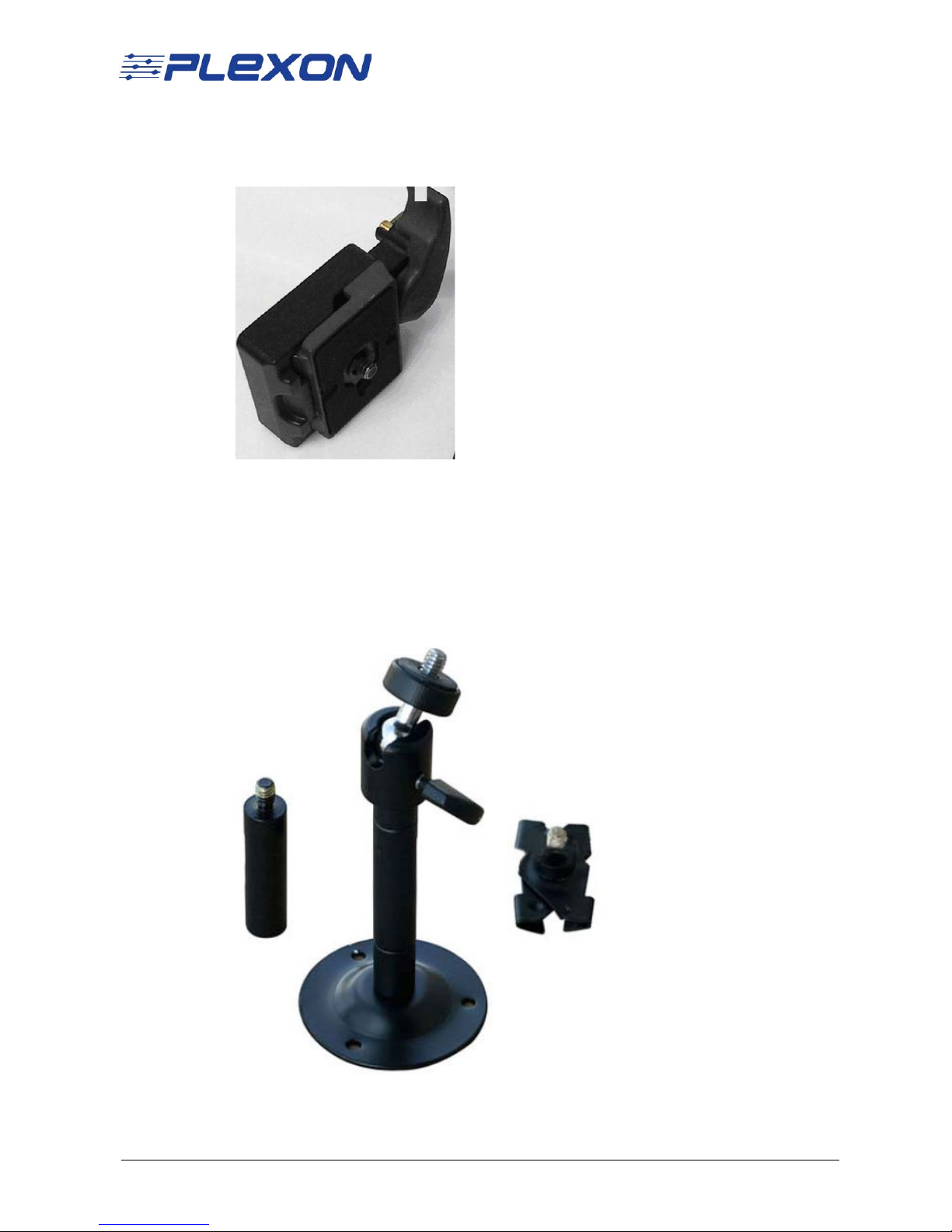
Quick Change Mounting Assembly
3
(Bogen-Manfrotto):
Note: The Quick Change Mounting Assembly (Bogen-Manfrotto) consists of
the Rectangular Quick Release Adaptor (Part No. 323) and Rectangular Plate
(Part No. 200PL).
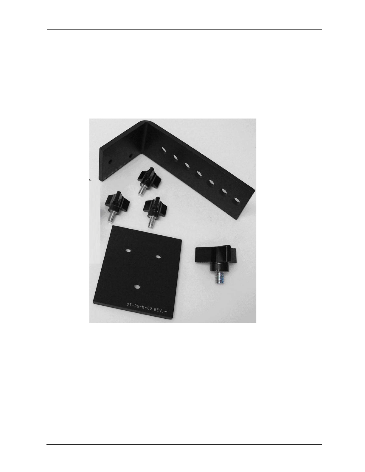
Universal Adjustable Camera Mounting Bracket
(VideoSecu Model MCB1B)
CinePlex Camera Mounting Guide Page 3
Page 4
1
3
4
2
5
3. Additional Mounting Accessories to Consider
Some experimental setups may require additional mounting hardware over and
above those supplied in the Plexon Mounting Kit. This section shows some
examples of parts you might find useful. See Section 5.3, "Examples of Camera
Installations" for some examples mounting these accessories.
All of the parts shown in this section can be purchased or machined by the
customer as needed.
1 Mounting Bracket
2 Sandwich Plate
3 Three Arm Phenolic Knob (small) - 1/4”-20 (3 ea.)(McMaster Carr
57715K16)
4 Three Arm Phenolic Knob (large) - 3/8”-16 (McMaster Carr 57715K83)
Page 4
Page 5
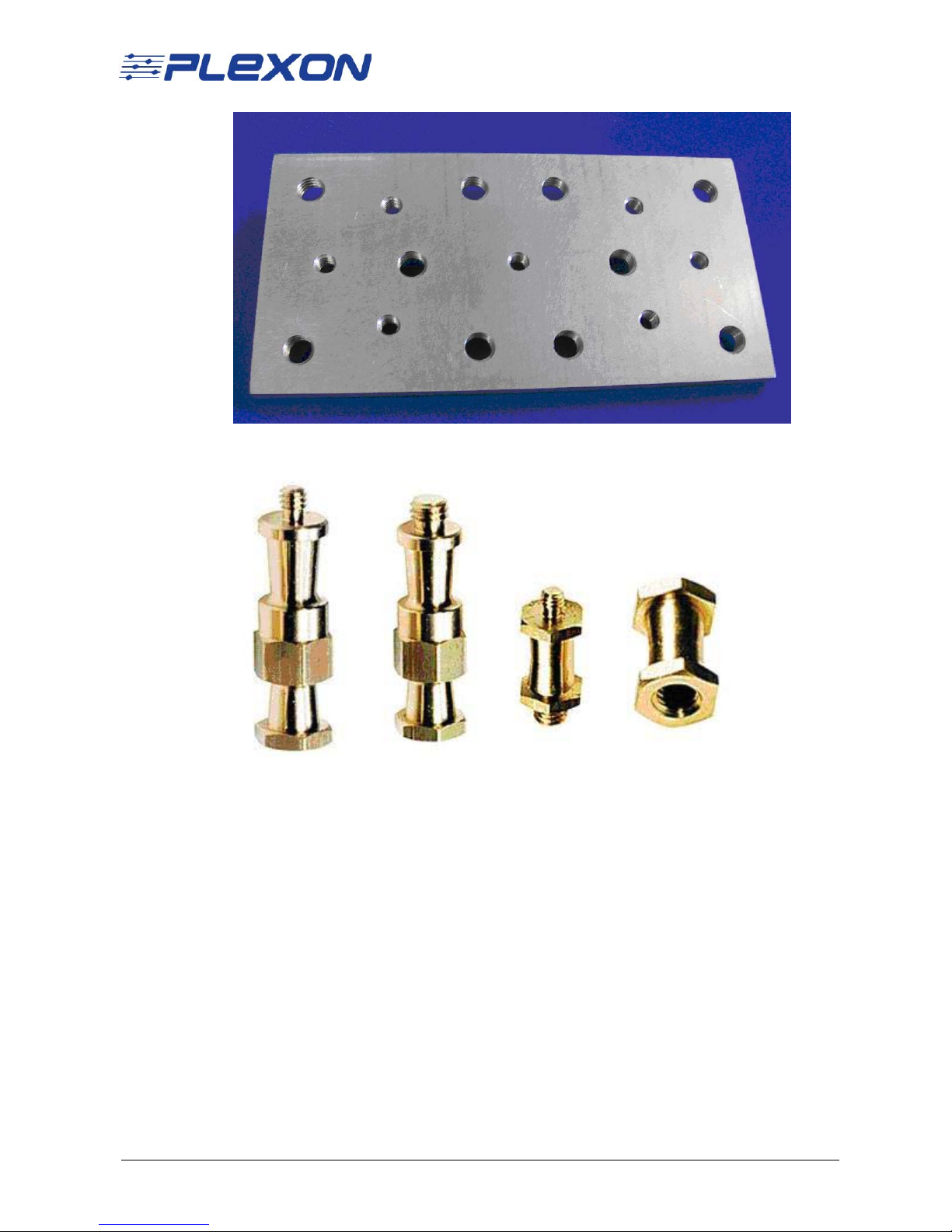
1 Camera Mounting Plate 3”x6” with threaded holes.
1
2
3
4
5
2 Stud 036-014 (1/4”-20 m x 1/4” 20 f)(Bogen Manfrotto 036-014)*
3 Stud 036-038 (3/8” m x 3/8” f)(Bogen Manfrotto 036-038)*
4 Stud 037 (1/4”-20 m x 3/8” m)(Bogen Manfrotto 037)*
5 Stud 066 (1/4”-20 f x 2/8” f)(Bogen Manfrotto 066)*
CinePlex Camera Mounting Guide Page 5
Page 6
6
7
8
6
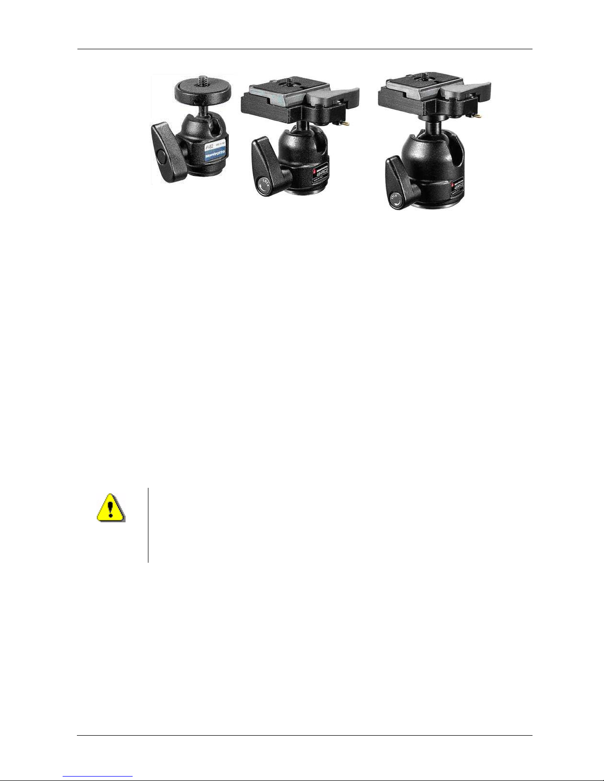
Ball Head - Micro (Bogen Manfrotto 482)*
7 Ball Head - Mini w/ RC2 (Bogen Manfrotto 484RC2)*
8 Ball Head - Compact w/ RC2 (Bogen Manfrotto 486RC2)*
To obtain these accessories, you might consider the following sources:
• Online - search for “Manfrotto” and the item number from many sources such
as:
— http://www.amazon.com/
— http://www.ritzcamera.com/
— http://www.bhphotovideo.com/
• A local professional camera or video store
CAUTION ABOUT TRIPODS
Note specifically that tripod mounting of the camera is NOT
RECOMMENDED. This is because tripod adjustments, particular ly leg
locking mechanisms, can loosen and become unstable. Tripods can
also be jostled or moved easily since they are generally not secure d
to a surface.
Page 6
Page 7

4. Bracket Mounting Methods
This section provides some examples of bracket mounting methods.
Camera Mounting Location
First, choose where the camera should be mounted. Common choices are shown
below:
Above the Experiment
• Ceiling mount
• Top of enclosure
a Inside of enclosure with room for cables
b Above the enclosure through an opening
c Inside of cage with room for cables
From the side of the Experiment
• Wall mount
• Side of enclosure
a Inside of enclosure with room for cables
b Outside of enclosure through an opening
c Inside of cage with room for cables
Below the Experiment
• Up through a glass or cage floor to view the undersides of animals or for birds
in perches
• Floor mount aimed up an animals in the air or above the floor
• Below enclosure
a Inside of enclosure with room for cables
b Below the enclosure through an opening
c Inside of cage with room for cables
CinePlex Camera Mounting Guide Page 7
Page 8
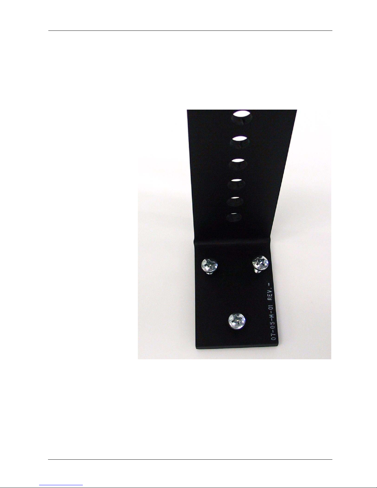
Bracket Attachment to Surface or Other Structure
Choose the most appropriate method of attaching the camera mounting bracket to
the desired location.
1 On a surface of a wall or ceiling over 0.4 in (1 cm) thick, use one of the fol-
lowing methods or devise a custom method.
a Customer provided screws through the three threaded holes in the bracket
into the wall. Wall anchors should be used as necessary.
b Customer provided bolts through the three threaded holes in the bracket
into a wooden surface. Pilot holes can be drilled, if needed, using the
sandwich plate as a template.
c Customer provided adhesive or epoxy to glue the surface of the mounting
bracket containing the three threaded holes to the surface.
Page 8
Page 9
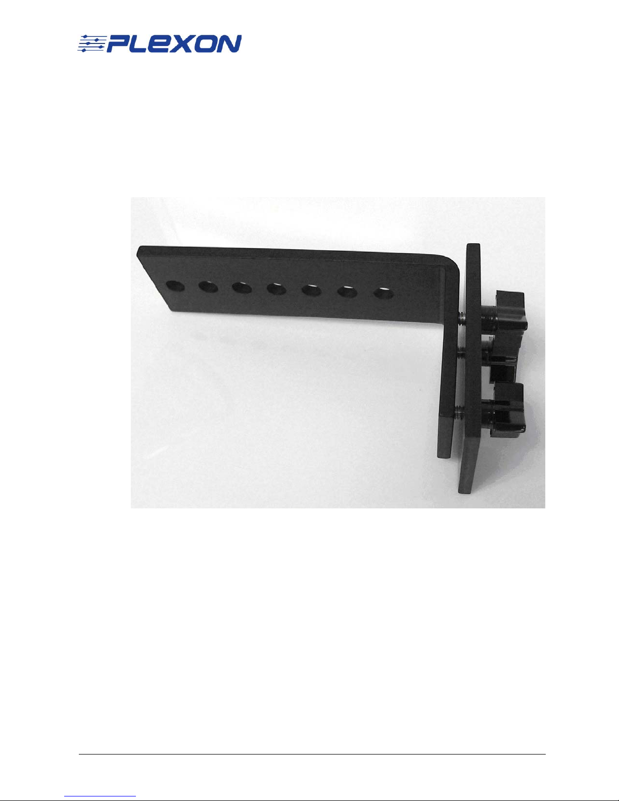
2 On a cage:
a Place the sandwich plate on the outside of the cage, then
b Insert the three small knobs through the sandwich plate holes and through
openings in the cage, then
c Thread the three small knobs into the threaded holes in the mounting
plate.
3 On a wall or surface under 0.4 inches (1 cm) thick:
a Drill three 9/32” (7 mm) holes using the sandwich plate as a template,
then
b Insert the three small knobs through the wall into the threaded holes in the
mounting plate.
CinePlex Camera Mounting Guide Page 9
Page 10
5. Installing the Camera
5.1 Procedure for Camera Installation
Note: This procedure assumes that you are using a mounting bracket and other
hardware shown in the diagrams below. Y our actual mountin g method might be
different than the examples shown here.
1 Power down all system components - computer, OmniPlex System, etc.
2 Select the bracket attachment method suitable for the experiment and install
the mounting bracket. Make sure that the mounting bracket is firmly attached
and stable.
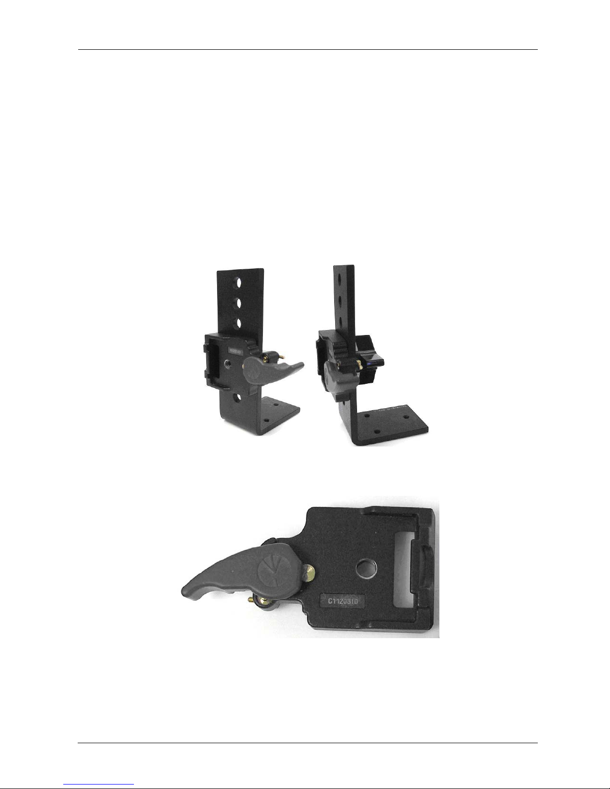
3 Install the rectangular plate adaptor on the mounting bracket using the large
phenolic knob. For most applications, the point of large lever should be
pointing away from the experiment when secured. Tighten finger-tight.
Page 10
4 Make sure that the large lever on the plate adaptor is in the open position and
ready to accept the plate. If the large lever cannot be moved easily, move the
small brass level to the unlock position, and try again.
5 Remove any cables from the camera, if present.
6 Attach lens to camera by screwing it on finger-tight.
Page 11
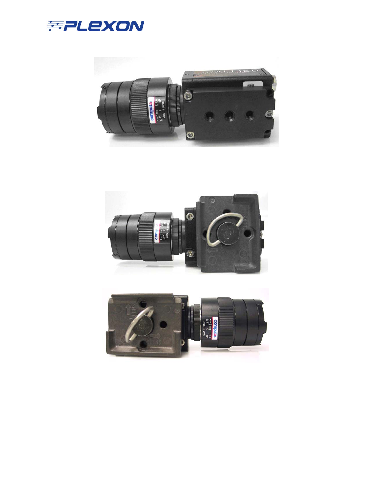
7 The adaptor plate should already be attached to the camera - if not, do so at
this time.
8 Attach the rectangular plate to the camera adaptor plate. For most
applications, the lens should be oriented in the position labeled “2 LENS”. use
the attached wire loop to finger-tighten the camera and then fold the loop
down.
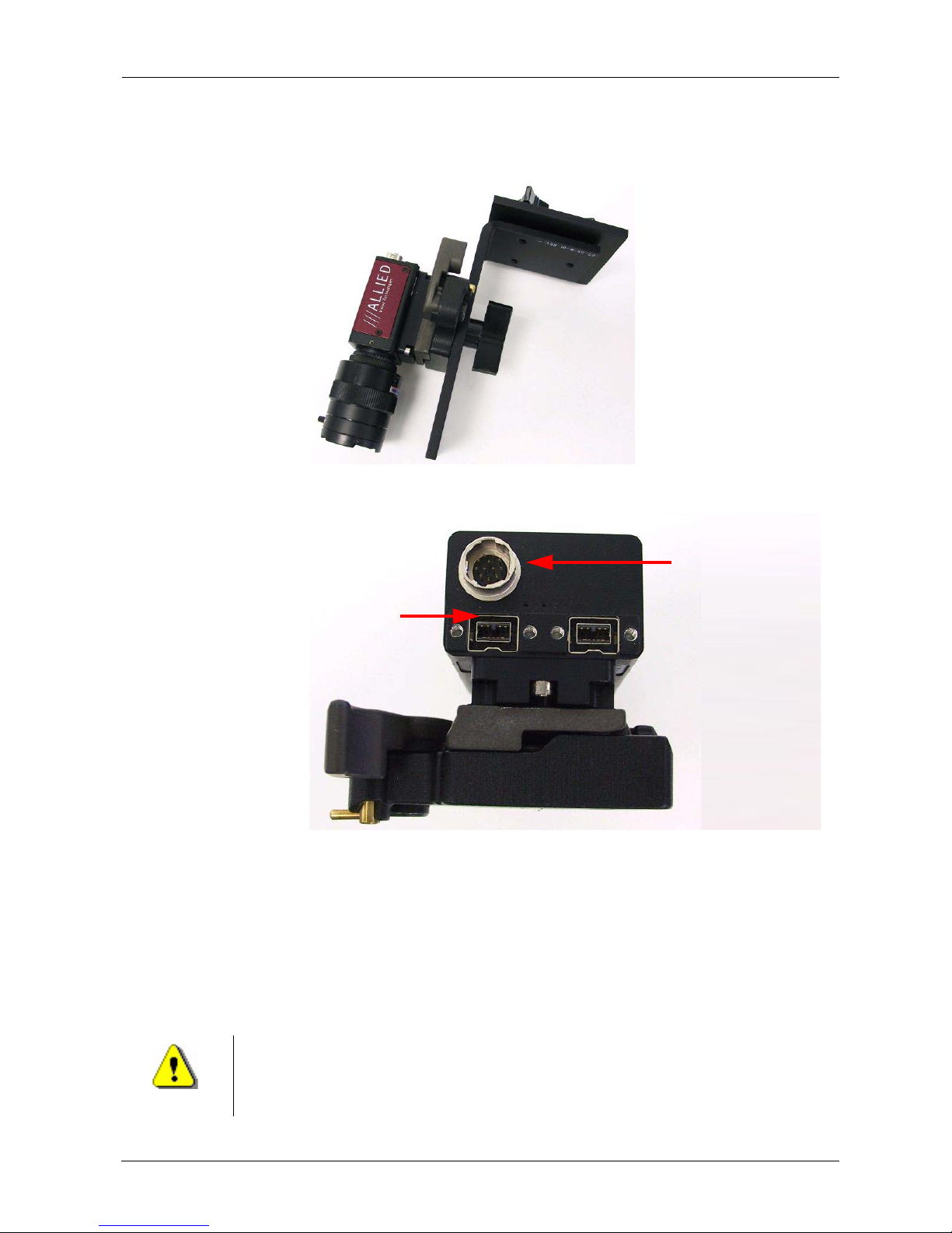
a Position “1 LENS” shown below
b Position “2 LENS” shown below
CinePlex Camera Mounting Guide Page 11
Page 12
1
2
Trigger cable
socket
FireWire
socket 1
9 Snap the camera/plate combination into the plate adaptor that is already
attached to the mounting bracket. Note that there is only one possible
orientation. The large lever will snap closed. Move the small brass lever to the
lock position. Make sure that the large lever cannot be unlocked.
10 Connect the FireWire cable(s) to the camera(s). Use the FireWire socket
labeled “1” in the photo.
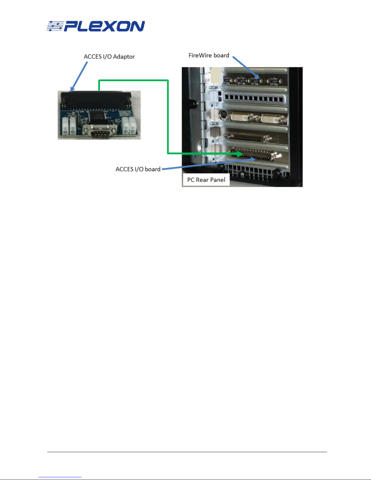
11 Connect the other end(s) of the camera FireWire cable(s) to any port(s) in the
FireWire board in the computer. Tighten the screws so that each plug is
secure in its socket.
12 Connect the camera trigger cable(s) to the trigger cable socket on the
camera(s).
13 Connect the other end(s) of the camera trigger cable(s) to any of the ports on
the ACCES I/O Adaptor on the computer (shown in the image below).
CAUTION
Never plug or unplug a camera FireWire cable with t he PC Po wer ON.
Permanent damage to the camera may result. Please note that any
damage due to this cause is not covered by the Plexon warranty.
Page 12
Page 13
Note: The following steps are a brief summary of the additional cabling
requirements and system startup procedures. The complete
procedures are provided in the CinePlex Studio Users Guide.
14 Make sure all other system cables are attached as required.
15 Turn on the OmniPlex chassis, then the PC. Open the OmniPlex Server and
PlexControl applications and start data acquisition in PlexControl. Then bring
up CinePlex Studio.
16 Loosen the large phenolic knob holding the camera/plate assembly to the
mounting bracket and adjust the camera orientation until the exp erimental
area is centered. Then tighten the large phenolic knob. It may also be
necessary to repeat Step 8 with the camera in the “1 Lens” position of more
adjustment latitude is needed.
17 Adjust the camera zoom until the experimental area fills the viewable image. If
this is not possible the camera may need to be moved closer to or further
away from the experiment. This can be done by selecting a differen t hole in
the mounting bracket for the adaptor plate attachment. If there is space
available, the mounting bracket may even be moved to the other side of its
mounting surface. If a satisfactory view is still not possible, contact Plexon
Support for additional lens options.
18 Adjust focus, and iris as needed for a good image.
5.2 Mounting Options for Multi-camera Systems
Place each camera as needed to record its area of interest. Make the choices
required for each position. Install each camera using the procedure appropriate
for your experiment.
CinePlex Camera Mounting Guide Page 13
Page 14
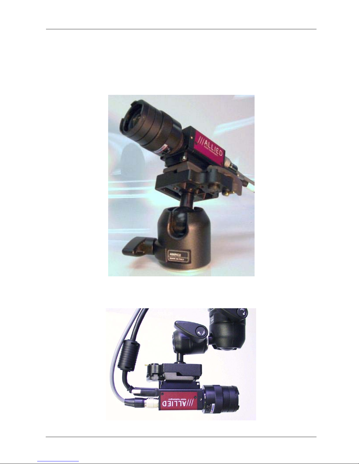
5.3 Examples of Camera Installations
This section includes some examples of camera installations. Obtain the customer
supplied accessories as needed for your experiment.
1 Using a Mini Ball Head between the camera and the mounting plate.
2 Using multiple ball heads to achieve difficult angles.
Page 14
Page 15
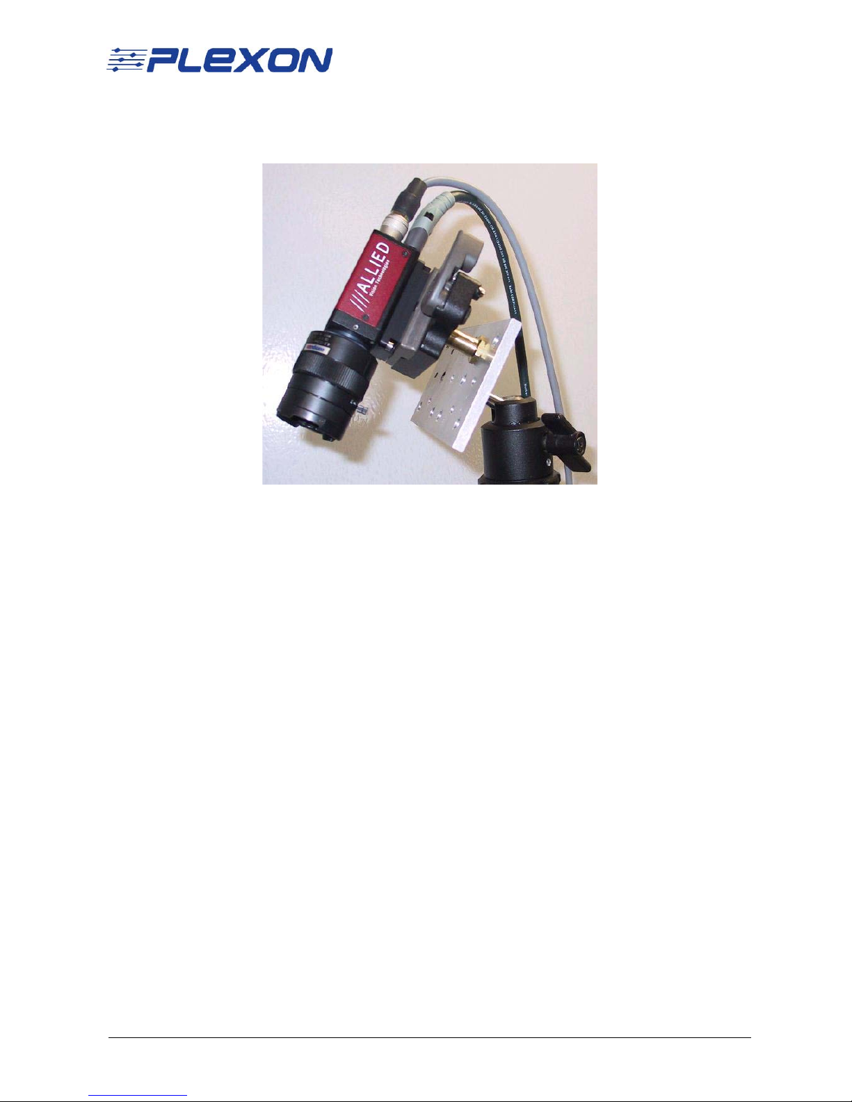
3 Using a camera mounting plate together with a ball head and stud 037 to
achieve an offset camera mount at a difficult angle.
6. Camera Removal
Procedure for Camera Removal
1
Power down all systems.
2 Remove all cables from the camera.
3 Move the small brass level to the unlock position if not already there.
4 Place a hand on the camera to catch it as it releases.
5 Move the large lever to the unlock position.
6 Catch the camera and place it in a safe location.
CinePlex Camera Mounting Guide Page 15
Page 16

This page intentionally left blank
Page 16
 Loading...