


Installation and user handbook – rev.0.4 of 23.02.2017
1
Congratulations
You have purchased a top quality product.
“EGO”
its components are produced 100% in Italy.
After its simple installation, you can enjoy the beauty of its design, the practicality of its
operation and the guarantee of its performances:
solar collector with integrated storage was designed by an Italian company, and all
Smart. Solar. Box

Installation and user handbook – rev.0.4 of 23.02.2017
2
CONTENTS
INSIDE THE BOX ............................................................................................................................... 5
OPTIONAL ACCESSORIES ............................................................................................................ 7
EXPLANATION OF THE SYMBOLS USED ................................................................................ 10
Abbreviated signs ............................................................................................................................. 10
Danger signs ..................................................................................................................................... 10
Personal Protective Equipment ....................................................................................................... 10
WARNINGS ....................................................................................................................................... 11
General indications .......................................................................................................................... 11
Indications for safety ....................................................................................................................... 11
Protection from vacuum overheating ............................................................................................. 12
Protection from burns ..................................................................................................................... 12
Protection against lightning ............................................................................................................. 13
LAWS AND REFERENCE STANDARDS .................................................................................... 14
SPECIFICATIONS ON WATER QUALITY.................................................................................. 15
Reference values .............................................................................................................................. 15
Limits of use ..................................................................................................................................... 16
Resistance to corrosion .................................................................................................................... 16
SYSTEM DESCRIPTION ................................................................................................................ 17
Technical characteristics .................................................................................................................. 17
A. the SOLAR COLLECTOR ...................................................................................................... 17
B. the STORAGE ..................................................................................................................... 18
Note on the integrated storage system ....................................................................................... 18
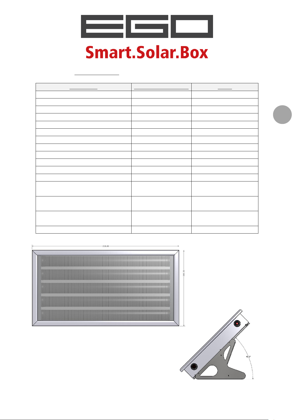
TECHNICAL DATA ............................................................................................................................. 19
Model EGO 110 ............................................................................................................................ 19
Model EGO 150 ............................................................................................................................ 20
Model EGO 180 ............................................................................................................................ 21
Model EGO 220 ............................................................................................................................ 22
Model EGO 260 ............................................................................................................................ 23
OPERATION PRINCIPLES ............................................................................................................ 24
INSTALLATION................................................................................................................................ 25
General indications and moving ...................................................................................................... 25

Installation and user handbook – rev.0.4 of 23.02.2017
3
Structural check ............................................................................................................................... 26
SAFETY PRECAUTIONS WHILE ASSEMBLING .................................................................................... 27
INSTALLATION ON A FLAT ROOF ...................................................................................................... 28
Place and position ........................................................................................................................ 28
Necessary items ........................................................................................................................... 29
Installation phases ....................................................................................................................... 30
Anchoring with ballasts ................................................................................................................ 35
INSTALLATION ON A SLOPED ROOF ................................................................................................. 37
Place and position ........................................................................................................................ 37
Necessary items ........................................................................................................................... 38
Installation phases ....................................................................................................................... 39
HYDRAULIC CONNECTION ......................................................................................................... 45
General layout .................................................................................................................................. 45
Indications on gaskets and connections ...................................................................................... 47
Using flexible hoses ...................................................................................................................... 47
Other indications ......................................................................................................................... 48
Assembling the safety and one-way valve ....................................................................................... 48
Assembling the safety unit (an alternative to the safety valve) .................................................. 49
Positioning and fixing the backflow preventer ................................................................................ 50
Pressure reducer .......................................................................................................................... 51
Thermostatic mixer valve............................................................................................................. 52
Connecting more than one collector ............................................................................................... 53
Examples of system layouts ............................................................................................................. 54
“EGO” ........................................................................................................................................... 54
Layout 1: hydraulic connection to a traditional boiler ................................................................ 54
Layout 2: hydraulic connection to a boiler prepared for operation with a solar power system 54
Expansion vessel .............................................................................................................................. 56
STARTING ......................................................................................................................................... 57
Using the cover sheet ...................................................................................................................... 57
Filling ................................................................................................................................................ 58
Working pressure ............................................................................................................................. 59
Non-use for short periods of time ................................................................................................... 60
Emptying the tank for maintenance and winter stopping .............................................................. 60

Installation and user handbook – rev.0.4 of 23.02.2017
4
ELECTRICAL INTEGRATION KIT ............................................................................................... 61
Types of electric resistor .................................................................................................................. 61
Installing the electric resistors ......................................................................................................... 62
Indications on using electric resistors .............................................................................................. 63
PROGRAMMED MAINTENANCE ........................................................................................................... 64
GUARANTEE CONDITIONS ......................................................................................................... 65
ENVIRONMENTAL PROTECTION .............................................................................................. 66
FINAL NOTES .................................................................................................................................. 66
SOLAR KEYMARK CERTIFICATION .......................................................................................... 67
Installation and user handbook – rev.0.4 of 23.02.2017
5
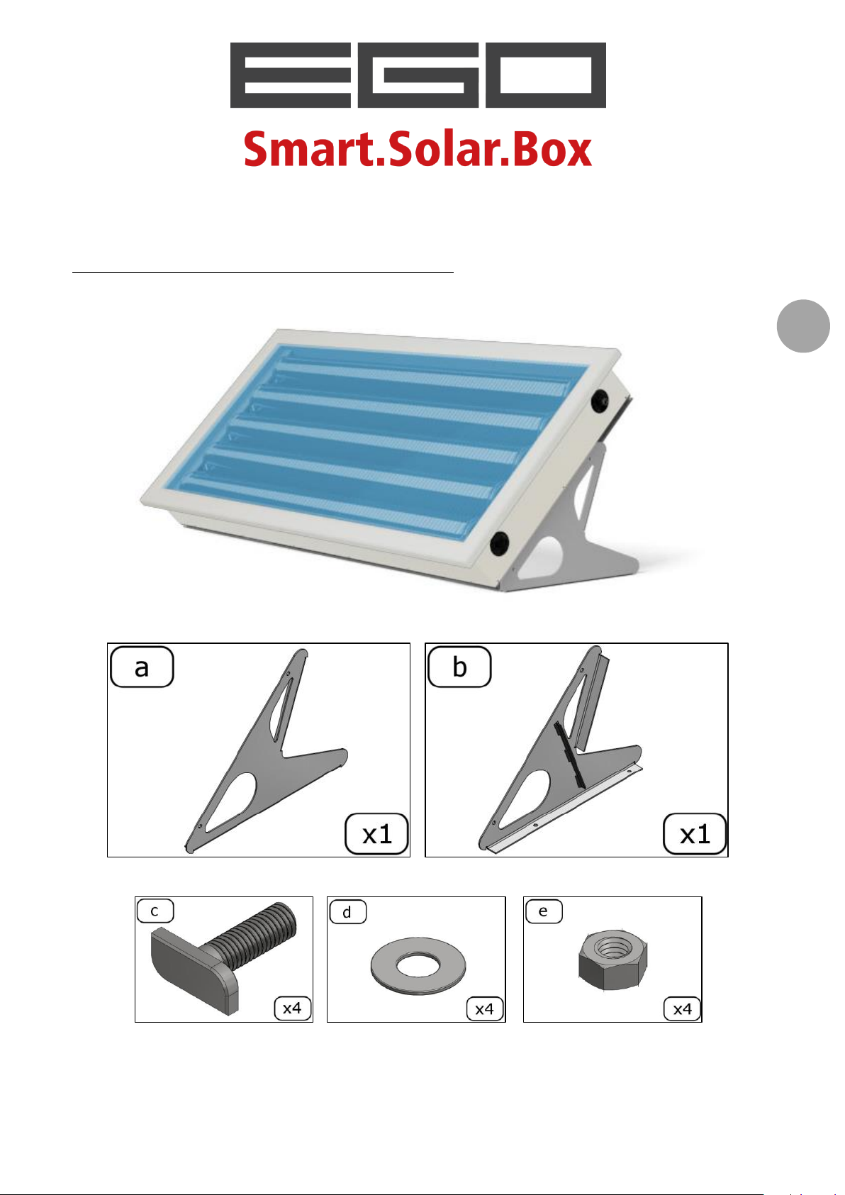
INSIDE THE BOX
Components that are supplied standard
…
Installation and user handbook – rev.0.4 of 23.02.2017
6
letter
component
quantity
[pieces] - “EGO”
solar collector with integrated storage
1
a b
BASIC SUPPORT: pair of galvanised sheet supports for flat roof
1 right +
1 left
c d e
hammer head screw, washer and nut for fixing
4
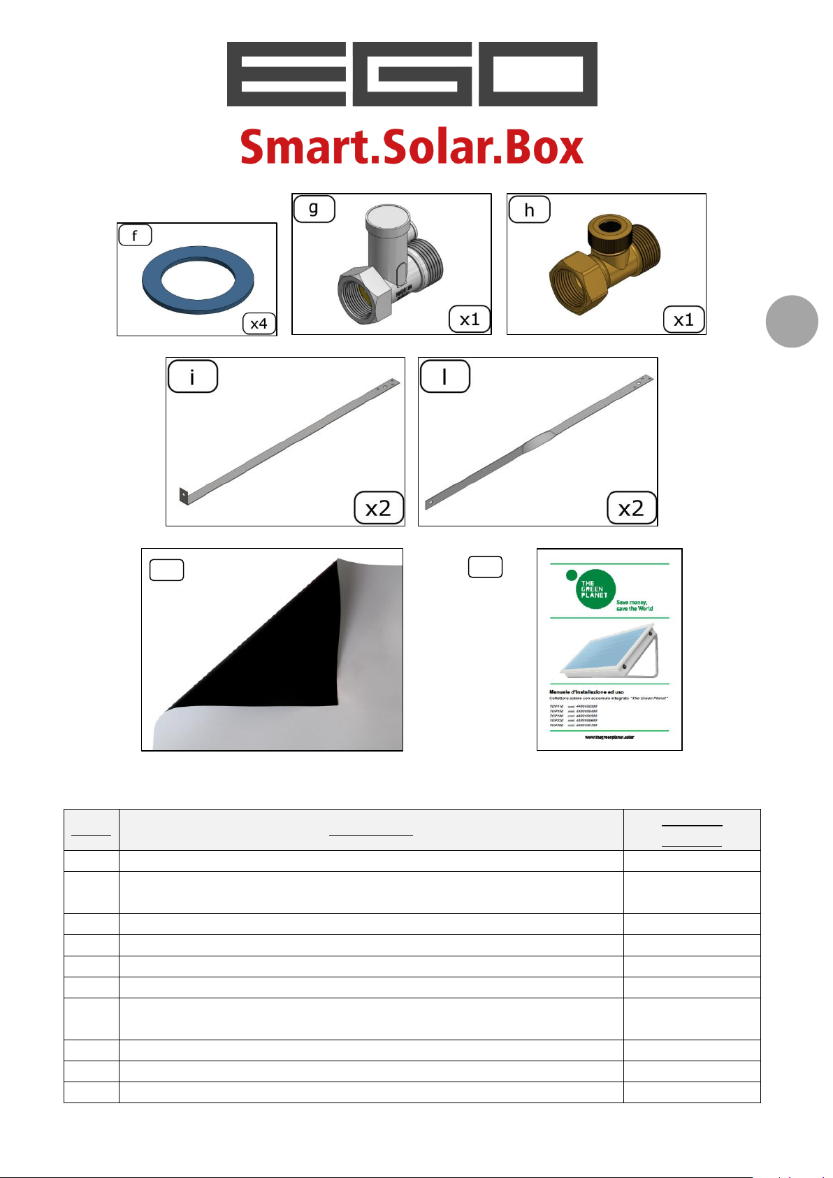
f
¾‟‟ flat gasket for high temperatures
4 g safety and one-way valve, MF ¾‟‟ connections
1
h
air feed valve (backflow preventer), MF ¾‟‟ connections
1
i
pair of lower fixing shafts, non-slip, made of AISI 304, for sloped
roof
2
l
pair of lower side fixing shafts made of AISI 304, for sloped roof
2
m
PVC cover sheet
1
n
installation and user handbook
1
m
n
Before starting to install the product, make sure all the components are present:
Installation and user handbook – rev.0.4 of 23.02.2017
7
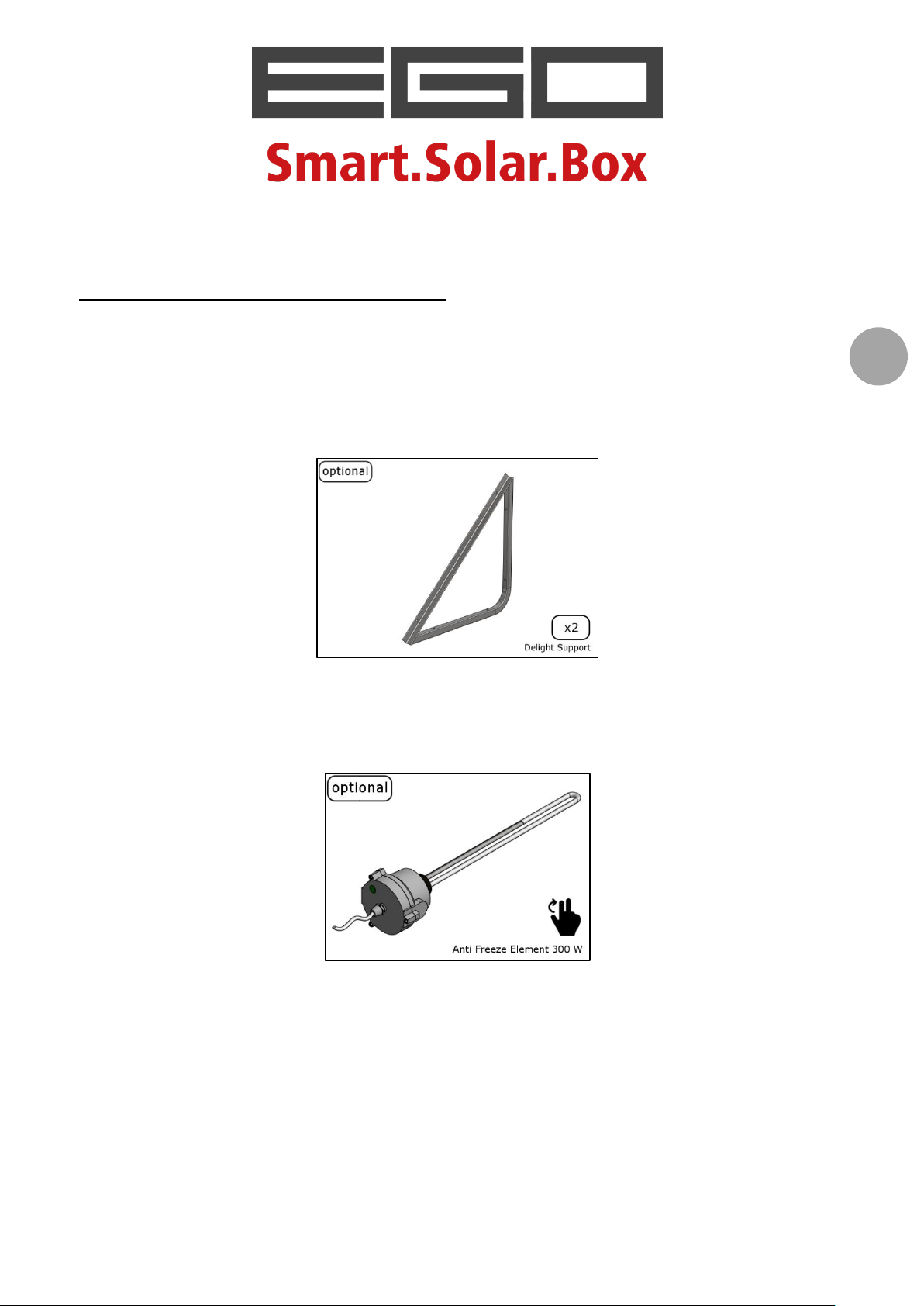
OPTIONAL ACCESSORIES
Accessories that can be requested
DELIGHT SUPPORT: pair of AISI 304 electropolished supports for flat roof
Article code:
(use the standard supplied hammer head screws, washers and nuts to connect to the solar
collector collector)
ANTI FREEZE ELECTRIC RESISTOR (power 300 W - 230V)
Article code:
4403XXXX00
4404XXXX00
4405XXXX00
4406XXXX00
4407XXXX00
4400234100
for EGO 110
for EGO 150
for EGO 180
for EGO 220
for EGO 260
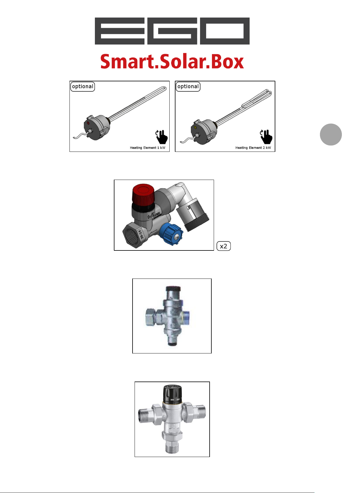
ELECTRICAL RESISTOR FOR INTEGRATION, 1 and 2 kW
Article code:
4400234101
4400234102
power 1,000 W – 230V;
power 2,000 W – 240V;
Installation and user handbook – rev.0.4 of 23.02.2017
8
SAFETY AND ONE-WAY UNIT, with MF ¾‟‟ connections
Article code:
PRESSURE REDUCER, with ¾‟‟ MF connections
Article code:
4400223301
4400223302
THERMOSTATIC MIXER VALVE, with ¾‟‟ MF connections
Article code:
4400224500

Installation and user handbook – rev.0.4 of 23.02.2017
9
Follow the component assembly instructions; if using accessories, follow their pertinent
options and limits of use.
Only use genuine components. Should it be discovered that non-genuine
components have been installed, the manufacturer can refuse all guarantee rights.
Installation and user handbook – rev.0.4 of 23.02.2017
10
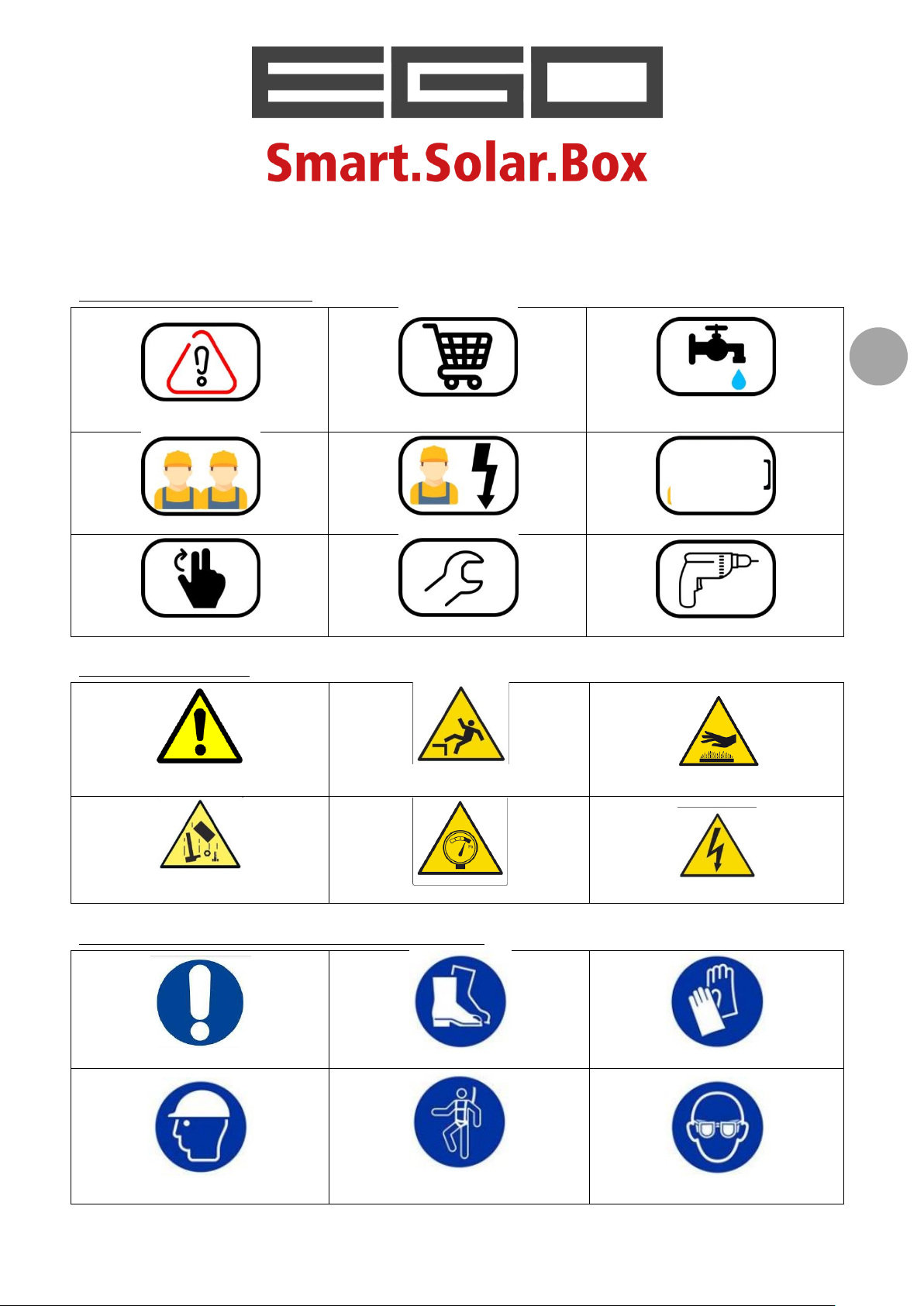
EXPLANATION OF THE SYMBOLS USED
important note
material to be obtained
(not supplied)
connection
to the water supply
2 people necessary
qualified electrician
qualified designer
tighten/loosen manually
tighten with spanner
perforate with drill
Danger!
Generic danger
Risk of falling
from a height
Risk of burns
Risk of falling
material from above
Danger of overpressure
Danger of electric shocks
PPE must be used
non-skid footwear must be used
cut resistant gloves must be worn
a protective helmet must be worn
PPE must be used when working at
heights
protective goggles must be worn
ABBREVIATED SIGNS
DANGER SIGNS
PERSONAL PROTECTIVE EQUIPMENT

Installation and user handbook – rev.0.4 of 23.02.2017
11
WARNINGS
GENERAL INDICATIONS
This document is an integral and essential part of the product. It is to be used by the
installer and the end user, who must keep it carefully after the system has been installed
and started.
The manufacturer is not liable for any damage deriving from incorrect observation of
the instructions and indications given in this document, those relative to possible
accessories supplied with the system and for the non-observance of pertinent
applicable national and local laws.
Before installation and use, obtain information on the current regulations and laws in
the place where the system is to be installed.
The
All technical drawings, plant layout and electric wiring diagrams etc. that are present in
The manufacturer is not liable for any damage caused to the product resulting from
“EGO”
produce domestic water that is heated by solar power. Any use other than that
indicated relieves the manufacturer from any responsibility and renders all guarantees
null and void.
this manual are indicative and are only given as examples. All connections, the safety
devices, diameter sizes and any other thing necessary for correct system installation
must be verified by a qualified and expert technician, who must make sure of their
correspondence with regulations and laws in force.
assembly that is not state-of-the-art.
solar collector with integrated storage was designed and manufactured to
INDICATIONS FOR SAFETY
This product must be installed by a professionally qualified company or technician,
according to national and/or local laws in force and the instructions given in this
handbook.
Maintenance and cleaning must also be carried out by specialist companies or staff with
the pertinent technical qualifications.
The term 'professionally qualified technician' indicates a person with specific technical
skills in water for domestic use, as well as in heating systems, gas systems and electric
systems. This person must have the professional skills indicated by law.
On the basis of the user guidelines, whoever uses the system must keep it in good
condition and guarantee that it works safely and correctly.
The system user must ensure that the maintenance indicated in this handbook (see the
PROGRAMMED MAINTENANCE chapter) is carried out.
Do not leave parts of the packaging or the system within the reach of children.
Installation and user handbook – rev.0.4 of 23.02.2017
12
Before cleaning or carrying out maintenance, disconnect the power supply from any
electric accessories that may be present.
Dispose of the various packaging elements in a suitable manner.
Check the pressure of the water transportation network: if the pressure is higher than
the nominal pressure of the product (4 bar = 400 kPa), prepare the necessary reduction
units before the connection and regulate the pressure (see STARTING chapter).
Should faults occur, or if the system does not operate correctly, do not attempt to repair
the product. Instead, disable it and contact a specialist technician. Should it be
necessary, components must only be replaced with original spare parts, which must be
installed by qualified technicians. Should this not be the case, the manufacturer
reserves the right not to recognise any guarantee rights.
PROTECTION FROM VACUUM OVERHEATING
The
“EGO”
sheet which darkens the surface that collects the sun's rays, therefore protecting the
product against overheating caused by direct exposure, above all in the case when the
collector has been installed but is not connected to the water system (therefore no water
present). The collector, in fact, was not designed to be exposed directly to the sun's rays
without being filled with water.
solar collector with integrated storage is supplied equipped with a PVC cover
Exposure to the sun when the system is empty can damage the product; in this
case the manufacturer will not recognise any guarantee rights.
The cover sheet must be left on the solar collector until it is started (see also the STARTING
chapter).
Should it be necessary to empty the system for maintenance or as a no-freeze function, it
should be covered by the cover sheet.
PROTECTION FROM BURNS
Danger! The water inside the collector can reach temperatures of approximately 90 °C.
To prevent the danger of burns and/or scalds, be extremely careful when:
- connecting the hydraulic supply to the domestic water supply;
- loading and unloading the system;
- carrying out any intervention on the hydraulic connection.
Installation and user handbook – rev.0.4 of 23.02.2017
13
Always position a thermostatic mixer valve between the system outlet and the
domestic water user (see HYDRAULIC CONNECTION chapter).
In general, do not touch the transport pipes or the hydraulic connections and the internal
accumulation tanks while the system is operating.
Should it be necessary to empty the system while it contains hot water:
- do not discharge directly onto the roof or into the ground;
- use a flexible hose to safely lead the water to a drain.
PROTECTION AGAINST LIGHTNING
Pursuant to the Directive EN 62305 1-4, the
integrated storage must not be connected to the protection system used by the building
against lightning, unless indicated otherwise by local laws in force.
EGO”
solar collector with
Have a technician or skilled electrician check the installation area for this
possibility.
All metal structures that are present, therefore also the supporting structure and fixing
shafts of the system, must have the same electric potential as the building. It is therefore
good practise to prepare suitable earthing for the metal parts of the system.
This can be done by a skilled electrician and the evaluation of the equipotentiality level
evaluated by a skilled electrical engineer.

Installation and user handbook – rev.0.4 of 23.02.2017
14
LAWS AND REFERENCE STANDARDS
Decree no. 37/2008 of 22 January 2008
UNI EN 12975-1:2006
UNI EN 12975-2:2006
UNI EN 12976-1:2006
UNI EN 12976-2:2006
UNI EN 9806:2014
UNI EN 1991:2004 PARTS 1-2,1-3,1-4 (Actions on structures)
Directive 97/23/EC
UNI EN 1717:2002
Legislative Decree no. 81 of 09 April 2008
Installation and user handbook – rev.0.4 of 23.02.2017
15
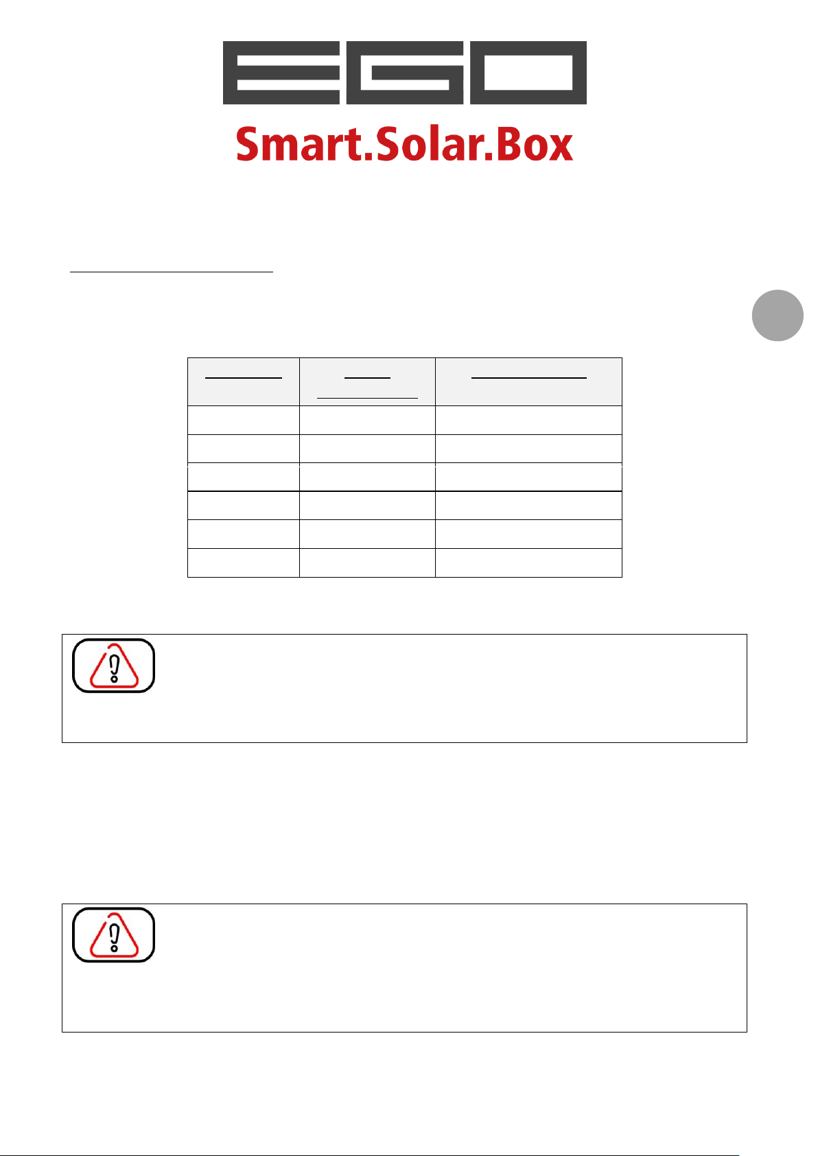
SPECIFICATIONS ON WATER QUALITY
parameter
unit of
measurement
reference value
pH - ≥6.5 and ≤9.5
hardness
°F
15-50
chlorides
mg/l
<250
free chlorine
mg/l
<0.2
iron
mg/l
<0.2
sulphates
mg/l
<250
REFERENCE VALUES
The characteristics of the water used can notably influence how well the product works
and how long it lasts. The supply water should respect the values given in the table below.
[source: Attachment I part C of Italian Legislative Decree no. 31 of 02 February 2001 and modified by
Leg.Decree no. 27 of 02 February 2002]
If the parameters do not fall within the reference values, the water being
supplied to the collector cannot be classified as
human consumption.
In these conditions of use, even though the product functionality and integrity are not
altered, the programmed performances cannot be guaranteed. The
with integrated storage, in fact, was designed to operate with drinkable water; the possible
formation of limestone or iron residues that deposit inside the accumulation can influence
the heating performance of the product. As an example, water with a high level of limestone
(hard) can cause losses in performance.
CAUTION! A reduction in the energy yield of the
integrated storage that can be traced back to using water that was not suitable for its
operation cannot be considered as a product defect; in this case the manufacturer will not
recognise any guarantee rights.
drinkable
and as such is not suitable for
EGO”
solar collector
“EGO”
solar collector with
Installation and user handbook – rev.0.4 of 23.02.2017
16
Should the supply water have values that exceed the reference limits given, above all if the
hardness is >26°F (15°T equal to 267 ppm of CaCO3), it is advisable to place suitable
filtering, scaling and/or softening devices downstream of the collector.
If you do not know the reference values of the water used, have a chemical analysis carried
out before installing.
LIMITS OF USE
The
“EGO”
excluding sea water, swimming pool water and fluids other than water.
solar collector with integrated storage can be supplied with any type of water,
Incorrect use of the supply fluid renders all guarantees on the solar collector
null and void (see GUARANTEES chapter).
RESISTANCE TO CORROSION
Beyond the indications given above, the components of
integrated storage that come into contact with the supply water were made using top
quality raw materials, and can resist higher levels of chemical aggression (corrosion) than
those that can occur in normal usage conditions.
With reference to the amount of chlorides in water, the standard limit of 250 mg/l was set
for the water to be defined as drinkable. In normal applications, this level is often exceeded
(500-700 mg/l), in some cases greatly (1,000 mg/l).
Given that with these values of chlorides the domestic water is not suitable for human use,
and in these cases the manufacturer will not recognise any guarantee rights, the tank in the
“EGO”
contact with the water can resist extremely high levels of chlorides (specific tests carried
out by accredited laboratories showed resistance to corrosion at values of beyond 4,000
mg/l of chlorides).
This characteristic gives the
limits and conditions of use that are much higher than those of similar systems.
solar collector with integrated storage and the other components that come into
“EGO”
solar collector with integrated storage application
“EGO”
solar collector with
Installation and user handbook – rev.0.4 of 23.02.2017
17
SYSTEM DESCRIPTION
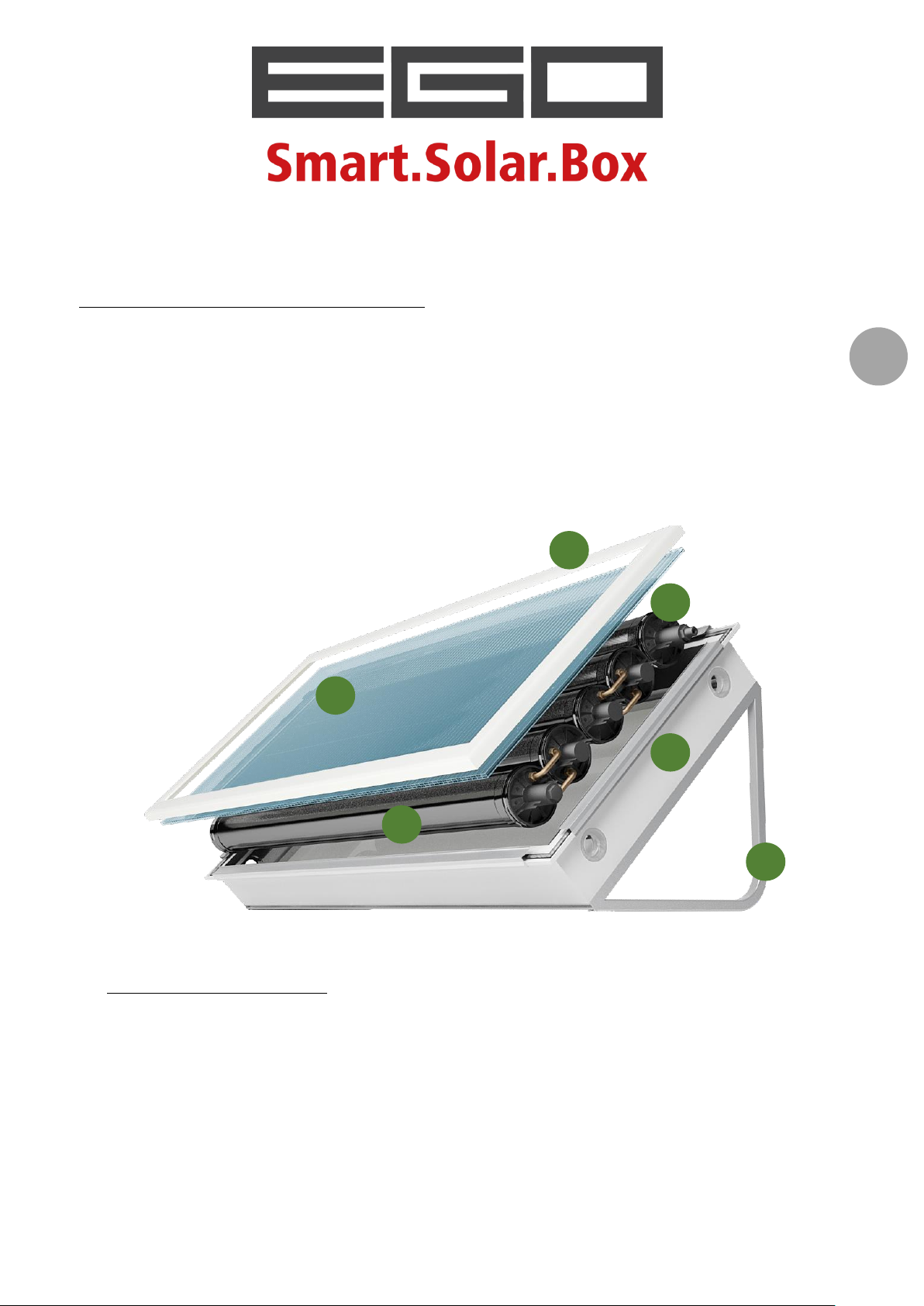
1
2
3
4 5 6
TECHNICAL CHARACTERISTICS
“EGO”
heated by solar power, to temperatures below boiling at atmospheric pressure in places
where ice does not form.
The system is made up of two integrated units:
A. the SOLAR COLLECTOR;
B. the STORAGE
solar collector with integrated storage is used for producing domestic water that is
A. the SOLAR COLLECTOR
The supporting frame of the collectors is made of aluminium profiles.
The external protective structure is made of a light heat-sealed PVC frame (1) that
resists UV rays.
The transparent cover is of POLICARB
has been anti-UV treated. In comparison with traditional solar glass, the sheet is 80%
lighter, it limits heat dispersion at night, it guarantees optimal transparency to solar
radiation and it increases resistance to bad weather.
®
(2), a 10 mm twin wall polycarbonate sheet that

Installation and user handbook – rev.0.4 of 23.02.2017
18
The upper frame is made of heat-sealed PVC (3) that can be removed to access the
accumulation tank. Light and UV-resistant, its design makes it suitable for any
architectural context.
The lower thermal insulation is made of a polyurethane foam panel, 30 mm thick, that is
coated with sheets of aluminium; the lateral insulation is made of 4 sheets of natural
fibre polyester, 25 mm thick.
B. the STORAGE
The domestic water accumulation system is made of a series of high-performing
stainless steel cylinders (4) made of a special alloy that resists high pressures and also
very corrosive water.
The cylinders are closed at their ends by special caps (5) made of thermoplastic
material loaded with glass fibre, to unite lightness and resistance.
The caps are connected to each other by copper connecting pipes, which allow the
water to move from one cylinder to the next.
The supports for flat roof (6) are available in two models:
- BASIC SUPPORT: pair of galvanised sheet supports (supplied standard);
- DELIGHT SUPPORT: pair of AISI 304 electropolished supports (accessories, available on
request).
Note on the integrated storage system
The
“EGO”
Directive (PED) for pressurised equipment, in relation to the fluid and working conditions to
which it is exposed.
It is a container that holds a group 2 (water) fluid, with steam pressure at the maximum
acceptable temperature below 0.5 bar in addition to the atmospheric pressure (1.033 bar).
As its threshold limits are below those indicated in art. 3.3 of Directive 97/23/EC:
"...for fluids in Group 2 with a pressure PS greater than 10 bar and a product of PS and
V greater than 10 000 bar 7L, or with a pressure PS greater than 1 000 bar (Annex II,
table 4)...";
"...piping intended for fluids in Group 2 with a PS greater than 10 bar, a DN greater than
200 and a product of PS and DN greater than 5 000 bar (Annex II, table 9)..."
this tank is not subject to CE marking, but the producer guarantees it (as established in the
directive) because "designed and produced following a correct construction procedure";
the accumulation system does not require CE marking.
solar collector with integrated storage was produced pursuant to the 97/23/EC
Installation and user handbook – rev.0.4 of 23.02.2017
19
TECHNICAL DATA
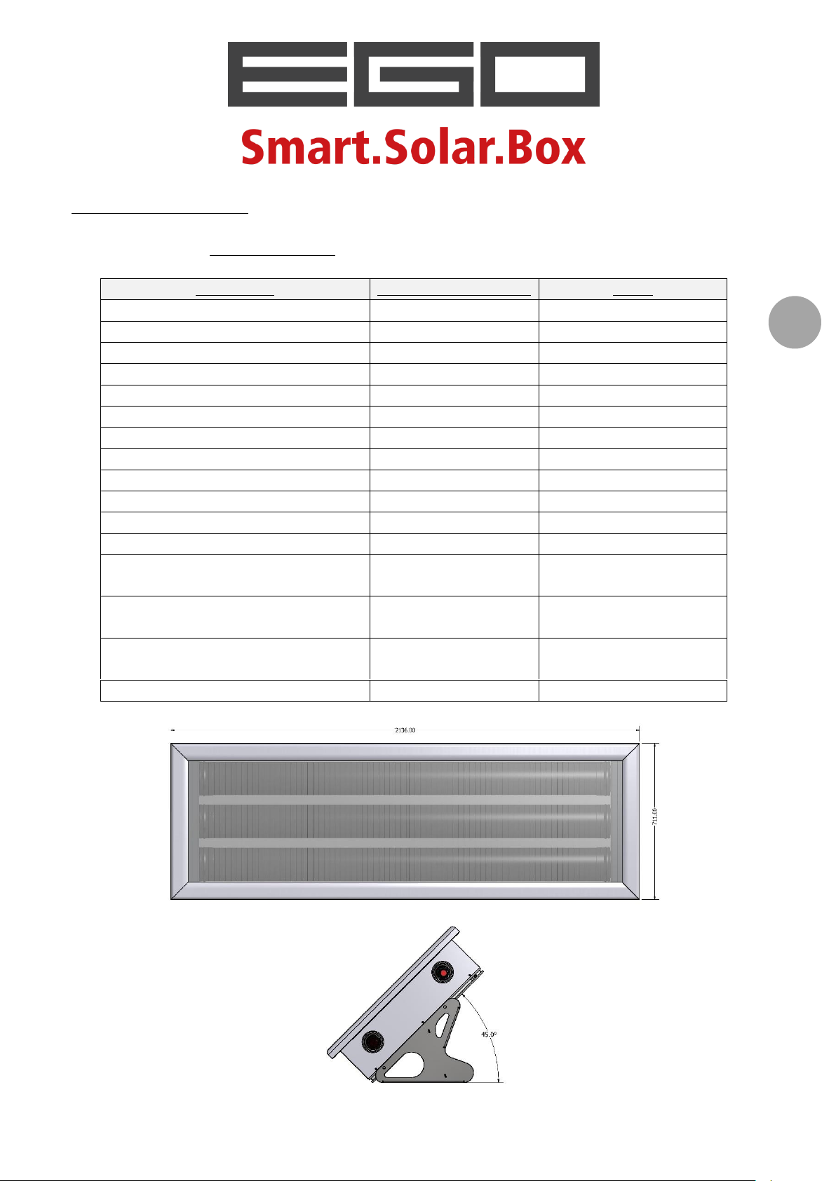
parameter
unit of measurement
value
external dimensions (L x P x H)
[mm]
2,136 x 711 x 217
gross surface area
[m2]
1.52
surface area when open
[m2]
1.09
absorption surface area
[m2]
0.85
effective ACS content
[litres]
105
cover requirements
[people]
1 – 2
net weight (empty)
[kg]
36
working weight (full)
[kg]
141
maximum working pressure
[kPa]
400
maximum working temperature
[°C]
90
heat-transfer fluid
[-]
ACS
hydraulic connections
[„‟]
2 x ¾‟‟ M
thickness and heat insulation type
[mm]
30 in PUR (bottom)
25 in polyester (lateral)
installation
[-]
flat roof
sloped roof
degree of slope
[°]
45° (flat roof)
15 – 60° (sloped roof)
bleed recommended at 45 °C
[l/d]
-
Model EGO 110 Article code:
4400100301
Installation and user handbook – rev.0.4 of 23.02.2017
20
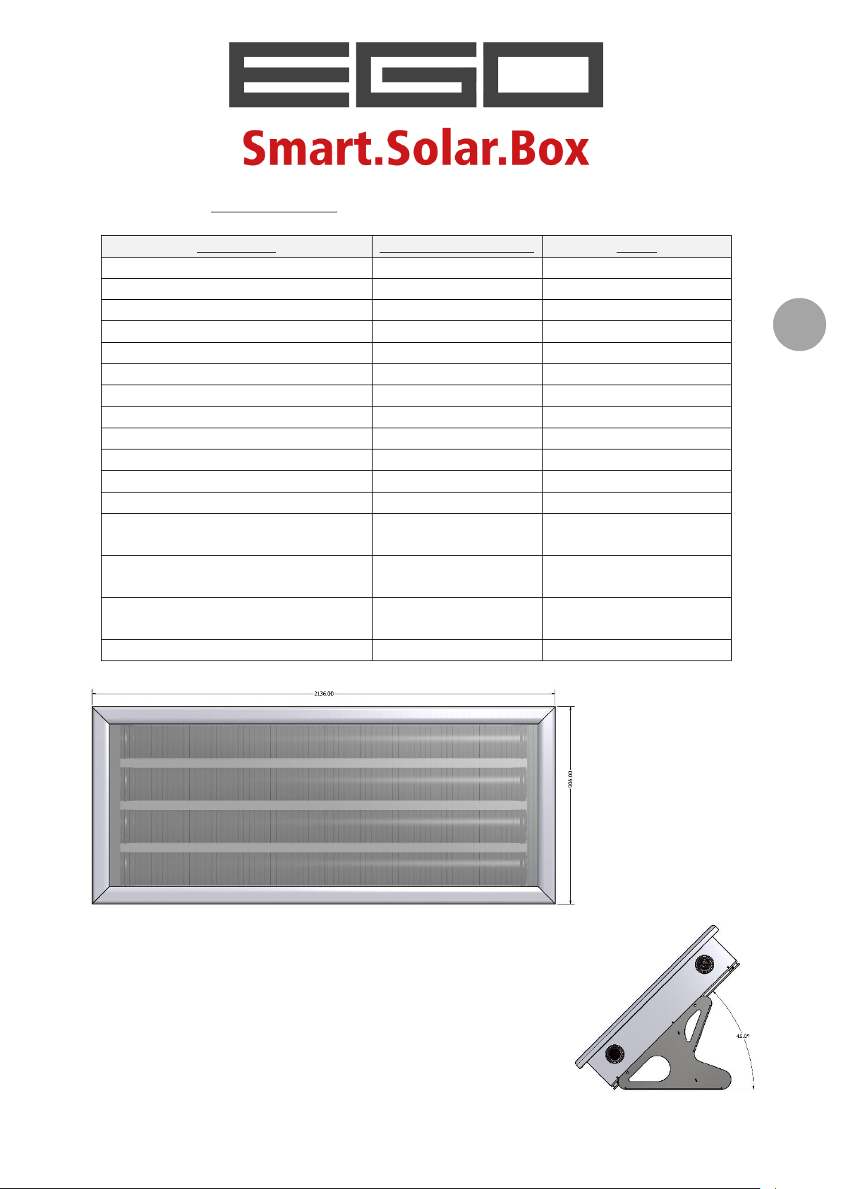
Model EGO 150 Article code:
parameter
unit of measurement
value
external dimensions (L x P x H)
[mm]
2,136 x 906 x 217
gross surface area
[m2]
1.93
surface area when open
[m2]
1.48
absorption surface area
[m2]
1.13
effective ACS content
[litres]
140
cover requirements
[people]
2 – 3
net weight (empty)
[kg]
43
working weight (full)
[kg]
183
maximum working pressure
[kPa]
400
maximum working temperature
[°C]
90
heat-transfer fluid
[-]
ACS
hydraulic connections
[„‟]
2 x ¾‟‟ M
thickness and heat insulation type
[mm]
30 in PUR (bottom)
25 in polyester (lateral)
installation
[-]
flat roof
sloped roof
degree of slope
[°]
45° (flat roof)
15 – 60° (sloped roof)
bleed recommended at 45 °C
[l/d]
-
4400100401
Installation and user handbook – rev.0.4 of 23.02.2017
21
Model EGO 180 Article code:
parameter
unit of measurement
value
external dimensions (L x P x H)
[mm]
2,136 x 1,101 x 217
gross surface area
[m2]
2.35
surface area when open
[m2]
1.86
absorption surface area
[m2]
1.41
effective ACS content
[litres]
175
cover requirements
[people]
3 – 4
net weight (empty)
[kg]
50
working weight (full)
[kg]
225
maximum working pressure
[kPa]
400
maximum working temperature
[°C]
90
heat-transfer fluid
[-]
ACS
hydraulic connections
[„‟]
2 x ¾‟‟ M
thickness and heat insulation type
[mm]
30 in PUR (bottom)
25 in polyester (lateral)
installation
[-]
flat roof
sloped roof
degree of slope
[°]
45° (flat roof)
15 – 60° (sloped roof)
bleed recommended at 45 °C
[l/d]
-
4400100501

Installation and user handbook – rev.0.4 of 23.02.2017
22
Model EGO 220 Article code:
parameter
unit of measurement
value
external dimensions (L x P x H)
[mm]
2,136 x 1,296 x 217
gross surface area
[m2]
2.77
surface area when open
[m2]
2.25
absorption surface area
[m2]
1.69
effective ACS content
[litres]
210
cover requirements
[people]
4 – 5
net weight (empty)
[kg]
57
working weight (full)
[kg]
267
maximum working pressure
[kPa]
400
maximum working temperature
[°C]
90
heat-transfer fluid
[-]
ACS
hydraulic connections
[„‟]
2 x ¾‟‟ M
thickness and heat insulation type
[mm]
30 in PUR (bottom)
25 in polyester (lateral)
installation
[-]
flat roof
sloped roof
degree of slope
[°]
45° (flat roof)
15 – 60° (sloped roof)
bleed recommended at 45 °C
[l/d]
-
4400100601

Installation and user handbook – rev.0.4 of 23.02.2017
23
Model EGO 260 Article code:
parameter
unit of measurement
value
external dimensions (L x P x H)
[mm]
2,136 x 1,491 x 217
gross surface area
[m2]
3.18
surface area when open
[m2]
2.64
absorption surface area
[m2]
1.98
effective ACS content
[litres]
245
cover requirements
[people]
5 – 6
net weight (empty)
[kg]
64
working weight (full)
[kg]
310
maximum working pressure
[kPa]
400
maximum working temperature
[°C]
90
heat-transfer fluid
[-]
ACS
hydraulic connections
[„‟]
2 x ¾‟‟ M
thickness and heat insulation type
[mm]
30 in PUR (bottom)
25 in polyester (lateral)
installation
[-]
flat roof
sloped roof
degree of slope
[°]
45° (flat roof)
15 – 60° (sloped roof)
bleed recommended at 45 °C
[l/d]
-
4400100701

Installation and user handbook – rev.0.4 of 23.02.2017
24
OPERATION PRINCIPLES
COLD WATER
HOT WATER
The
“EGO”
system in which the accumulation tank also acts as an absorber (direct exchange).
The accumulation system is struck directly by the sun's rays, which pass through the
transparent cover and transfer their thermal energy directly to the domestic water, which
is contained in special steel cylinders.
The accumulator (the volume of which varies according to the selected size) is quickly
heated by the sun. The water supply is positioned in the lower part of the system; it heats
up as it passes from the lower cylinders to the upper ones and finally exits from the highest
cylinder and goes into the system (directly to the user, for preheating a boiler - see the
STARTING chapter).
The special configuration of the tank ensures that the inflow water (cold) cannot be mixed
with the outflow water (hot).
solar collector with integrated storage is a natural circulation solar heating
Water circulation is guaranteed by the network pressure (waterworks, well,...). When the
tap downstream of the system is opened, the hot water exits from the upper section and the
same amount of cold water enters the lower section of the system.

Installation and user handbook – rev.0.4 of 23.02.2017
25
INSTALLATION
GENERAL INDICATIONS AND MOVING
Assembly, maintenance and cleaning must only be carried out by companies and
specialist staff.
The components indicated in this handbook must be used when assembling. The use of
other material is under the responsibility of the installer, who assumes full
responsibility, including the product guarantee.
The manufacturer is not liable for any work not carried out in a state-of-the-art manner,
as defined in Decree 37/2008, and for any damage caused to the structure or the tools
used.
Before installing and using the system, it is advisable to check local regulations and
laws to make sure that what is described in this document complies with them. Should
they be different, do not install the system and contact the manufacturer.
The manufacturer is not liable for any damage caused to things and injury to people as a
result of installation carried out without respecting local regulations and laws.
The system can only be moved when empty and extremely carefully. Do not
use or apply force to the plastic threaded connections in order to lift the product.
Avoid knocks and pressure on the system, in particular on the cover, base and the
plastic connections that project from the frame.
Do not place any load on the system.
When moving, always use people who are competent, trained and equipped according
to what is imposed by laws in force. Always use means of transport, lifting devices,
chains and any other things that are of a suitable capacity and size.

Installation and user handbook – rev.0.4 of 23.02.2017
26
STRUCTURAL CHECK
The
“EGO”
structure (attic, covering, balcony, etc...) that can support the device weight and dynamic
actions caused by variable things (e.g. wind, snow,...), considered with the presence of
“EGO”
of the static capacity of the structural elements and anchors used must be carefully
evaluated, according to what is indicated in the technical standards for construction (NTC
2008, in Italy), or the Eurocodes (EN 1991, in Europe). This check must be carried out by a
structural technician who is authorised to work in the installation area.
Be very careful of the load increase caused by snow or strong wind. The manufacturer is
not responsible for damage to things or injury to people caused by bad installation on
structures that cannot support the indicated loads.
solar collector with integrated storage can be placed on the ground or on a
solar collector with integrated storage.
In the case of already-existing buildings in particular, all combinations

Installation and user handbook – rev.0.4 of 23.02.2017
27
SAFETY PRECAUTIONS WHILE ASSEMBLING
Danger caused by wind
Install when the weather conditions are good, avoid rainy days and strong winds.
Danger caused by things falling from a height
Solar systems often need to be installed at a height.
Operators must follow regulations and laws in force regarding safety.
Danger caused by hanging loads and material falling from a height
If material needs to be lifted using a crane or machinery, apply all the pertinent
recommendations and regulations in order to carry out these operations safely. Use
suitable means of the correct capacity. Mark off the area where the lifting is being carried
out, to prevent risks caused by objects falling from a height.
If there are no collective fall arrest systems (e.g.: railings, protection nets, etc...) personal
protective equipment (PPE) must be used to prevent falls, as defined by safety at work
standards in force.
The usual PPE must be worn for all installation operations (drilling, moving, etc...).
Risk of electric shock
Only work near overhanging power cables where contact is possible if:
the power has been disconnected from the cables for the whole duration of the work
to be done
the cables are protected by suitable barriers or safety guards
the cables are more than 5 m away from where the work is being carried out.

Installation and user handbook – rev.0.4 of 23.02.2017
28
INSTALLATION ON A FLAT ROOF
Never remove the cover sheet if you have not finished installing the panel and
if the collector has not been filled. The
not designed to be exposed to sunlight when empty.
Do not move or force the solar collector using the threaded connections or the caps.
Place and position
Select an installation place that makes it possible to reduce accidental
loads (wind, snow, etc...) to which the system can be subjected. As an example, avoid areas
where vortexes form, or which are subjected to wind because of thermal inversion. If
situations like this are present, get a structural technician to check the maximum structure
loads.
If installing on a flat roof, position the collector at least 1-2 metres from the edge.
If installing on the ground, position the collector at least 1-2 metres from any obstacles that
are present.
Direct the transparent surface as close to the south as possible. If deviated slightly towards
the east or the west, the system still works in a satisfactory manner. Choose an installation
area where the panel remains in the sunlight for as long as possible. Nearby obstacles
(trees, buildings, etc...) can temporarily shade the system and reduce (even greatly) its
performance.
If positioning several collectors behind each other, do not let them shade each other. To
prevent this, keep enough distance between them to permit radiation without shade when
the sun is at an angle of 15° from horizontal.
“EGO”
solar collector with integrated storage was
For the system to operate correctly, install the collector at an angle of
between 15 and 60°. The supplied supports, if placed on a flat surface, give 45° installation.
The anchor points must all be on the same supporting surface. Any torsion force caused by
supporting points that are not aligned can damage the system.

Installation and user handbook – rev.0.4 of 23.02.2017
29
The longest side of the collector must always be supported by the surface. Do not install
the collector with the short side (where the connections are) against the surface.
Do not turn the collector upside down. The outflow should be positioned at the top, and can
be identified by its red cap (inflow at the bottom, identified by a blue cap). Correct
operation cannot be guaranteed if the system is installed upside down.
Necessary items
2 spanners, 13 mm
individual PPE (helmet, gloves, goggles, etc...)
Danger! The screws for fixing the supports to the roof are not supplied. They
must be obtained by the installer, following the indications of the structural technician.

Installation and user handbook – rev.0.4 of 23.02.2017
30
Installation phases

Installation and user handbook – rev.0.4 of 23.02.2017
31

Installation and user handbook – rev.0.4 of 23.02.2017
32

Installation and user handbook – rev.0.4 of 23.02.2017
33

Installation and user handbook – rev.0.4 of 23.02.2017
34

Installation and user handbook – rev.0.4 of 23.02.2017
35
Anchoring with ballasts
If
the roof structure because the supporting surface cannot be drilled (e.g. because of
waterproof coating) and if the supporting structure is strong enough (ask a structural
expert for confirmation), the system can be anchored to ballasts that are sized according to
the wind and snow, as well as to the weight of the collector when both full and empty.
“EGO”
solar collector with integrated storage cannot be anchored to

Installation and user handbook – rev.0.4 of 23.02.2017
36
Examples of ballast
In particularly windy areas, an additional safety system should be added to the ballasts,
with a suitably-sized steel cable anchored to a solid part of the building that can hold the
system.
The ballasts and cable must be sized by a structural technician who is
authorised to work in the installation area, as indicated by Eurocodes (EN 1991) or NTC
2008 (Decree 14 February 2008) if in Italy. The structural technician must also verify the
resistance of the building.

Installation and user handbook – rev.0.4 of 23.02.2017
37
INSTALLATION ON A SLOPED ROOF
Never remove the protective sheet if you have not finished installing the panel,
and if the collector has not been filled. The “
was not designed to be exposed to sunlight when empty.
Do not move or force the system using the threaded connections or the caps.
Place and position
Carefully check the state of the cover and the supporting structure. Get
a structural technician to check the maximum loads of the building, considering the weight
of the system when full as a permanent load, as per the UNI EN 1991 (Eurocode)
verifications.
Prefer the slope that faces south. Alternatively, the system works in a satisfactory manner
when positioned on a roof slope that is positioned slightly to the south-east/south-west.
Choose an installation area where the panel remains in the sunlight for as long as possible.
Nearby obstacles (trees, buildings, etc...) can temporarily shade the system and reduce
(even greatly) its yield.
EGO
” solar collector with integrated storage
For correct operation, install the collector at an angle of no less than 15°; the
collector must, in any case, be against the slope, therefore follow the angle of the roof.
The collector must always have its longest side parallel to the roof eaves. Do not install the
collector with its short side parallel to the eaves.

Installation and user handbook – rev.0.4 of 23.02.2017
38
Do not turn the collector upside down. The outflow side should be positioned at the top, and
can be identified by its red cap (inflow at the bottom, identified by a blue cap).
Correct operation cannot be guaranteed if the system is installed upside down.
Necessary items
2 spanners, 13 mm
individual PPE (helmet, gloves, goggles, etc...)
Danger! The screws for fixing the supports to the roof are not supplied. They
must be obtained by the installer, following the indications of the structural technician.

Installation and user handbook – rev.0.4 of 23.02.2017
39
Installation phases

Installation and user handbook – rev.0.4 of 23.02.2017
40

Installation and user handbook – rev.0.4 of 23.02.2017
41

Installation and user handbook – rev.0.4 of 23.02.2017
42

Installation and user handbook – rev.0.4 of 23.02.2017
43

Installation and user handbook – rev.0.4 of 23.02.2017
44

Installation and user handbook – rev.0.4 of 23.02.2017
45
HYDRAULIC CONNECTION
letter
component
obligatory
standard supply
recommended
OPZ
optional, can be
requested
OPZ
optional
X
not available
A
inflow line from the water system
-
-
B
water filter
X
C
pressure reducer
(adjusted at 3 bar)
OPZ
D
interception valve
X
E
safety and one-way valve
(setting 4.5 ± 0.5 bar)
F
discharge tap
X G flexible hose
X
H
expansion vessel
X
I
electric resistance for integration
(1,000 and 2,000 W)
OPZ
OPZ
L
antifreeze electric resistance
(300 W)
OPZ
OPZ
M
backflow preventer
N
thermostatic mixer valve
OPZ
O
inflow line to the user
-
-
The
“EGO”
M thread for connection to the line using flat gaskets (supplied).
GENERAL LAYOUT
With standard installation, follow the basic hydraulic connection layout.
Key of the symbols used in the drawing and synopsis of the compulsoriness/supply.
solar collector with integrated storage is equipped with 2 connections with 3⁄4“

Installation and user handbook – rev.0.4 of 23.02.2017
46

Installation and user handbook – rev.0.4 of 23.02.2017
47
The components surrounded by a broken line, identified by this icon, make up
a basic set that is always present in all possible system configurations. For simplicity, these
components are not shown in other hydraulic drawings, but their presence is indicated by
the relative icon.
The connection drawing that is represented, just like those on the following pages, is purely
indicative and only indicates how to connect the hydraulic connections and install the main
supplied components and the requested accessories.
Hydraulic connection is the responsibility of the installer; he/she has the task
of verifying if what is indicated in this manual complies with laws and regulations in force at
the installation place.
The manufacturer is not liable for any damage caused to things and injury to people as a
result of installation carried out in a manner that is not state-of-the-art, and without
respecting local regulations and laws.
Indications on gaskets and connections
The external components of the
of plastic, to reduce thermal dispersion.
The connections were created for the use of gaskets with flat seal.
“EGO”
solar collector with integrated storage are all made
Only use the flat washers supplied with the collector and the valves to seal the
connections.
Do not use other types of seal or additional seals, such as hemp, Teflon, sealing paste or
similar. No guarantee rights will be recognised if seals or additions other than those
supplied are used.
When tightening the connections:
make sure the gaskets are positioned correctly;
use a spanner and a torque wrench;
use the spanner to keep one of the two connections steady, so that it does not move
from its seat, and to prevent damaging the connection;
tighten the other connection using the torque wrench, without exceeding a tightening
torque of 20 Nm.
Using flexible hoses
Only removable connections (e.g. stainless steel bellows and flexible pipes) must be used
to connect the water lines to the valves on the solar collector connections.

Installation and user handbook – rev.0.4 of 23.02.2017
48
This compensates the thermal expansion of the lines caused by temperature oscillations
and makes disconnecting and repositioning the solar collector easier if it has to be
removed.
Make sure the connecting pipes, once installed, can move in order to
guarantee suitable thermal expansion.
It is advisable to use a connecting system that is not fixed (e.g. staples).
Other indications
Only use water supply pipes that are suitable for the domestic sector and that can resist a
temperature of at least 120 °C.
In order to reduce thermal dispersion and prevent the risk of freezing, it is advisable to
insulate the pipes that supply the collector with water and towards the user with insulation
material of suitable thickness; for outdoor pipes use material that is UV-resistant.
ASSEMBLING THE SAFETY AND ONE-WAY VALVE
To limit excess pressure in the hydraulic circuit, the safety and one-way valve supplied with
the collector must be installed upstream of the inflow connection.
This solution prevents the system from emptying if there is no water being supply. When
uniting, use the supplied pair of ¾‟‟ flat gaskets.
This component acts as:
- a safety valve, with opening set at 4.5 ± 0.5 bar;
- a one-way valve, to stop the water from returning to the water system.
If you want to install a discharge valve at inflow (recommended), it should be positioned
between the safety valve and the inflow connection.
The safety valve must be installed correctly; if it is not, leaks can occur. No
guarantee rights will be recognised if not installed or if installed correctly.

Installation and user handbook – rev.0.4 of 23.02.2017
49
Assembling the safety unit (an alternative to the safety valve)
For installations in Italy and in countries where a regulation similar to the one established
by Ministerial Circular no. 829571 of 26 March 2003 regarding accumulation water heaters:
"...these devices must be connected to the domestic water system using a hydraulic safety unit. This
unit must include at least one interception tap, a one-way valve, a control device for the one-way
valve, a safety valve, a hydraulic charge interrupting device, all accessories necessary for using the
water heaters safely. The design, production and operation criteria of the hydraulic safety units are
those defined by the European Commission Regulation EN 1487:2002...”
one-way valve is not suitable and must be replaced with a safety unit that complies with the
above standard.
The supplied valve only answers the EN 1717 regulation defined in section 5.4 of the EN
12976-2 regulation.
To comply with the indications above, the installer can choose whether to assemble the
individual devices listed above, or install the SAFETY AND ONE-WAY VALVE, available as
an optional accessory on request (code
4400223301
).
It includes a valve body, with MF ¾‟‟ connections, that contains several elements:
the safety and outflow valve, set at 4.5 ± 0.5 bar;
the one-way valve, with control device (can be inspected, self-cleaning);
the device for interrupting the hydraulic load;
the stopcock;
an adjustable outflow trap.
, the supplied safety and
Danger! Do not assemble the safety system together with the safety and one-
way valve.
Installing the safety system is an alternative to using the safety and one-way valve
(standard supplied).

Installation and user handbook – rev.0.4 of 23.02.2017
50
POSITIONING AND FIXING THE BACKFLOW PREVENTER
The
“EGO”
a backflow preventer (or air feed valve) that is assembled on the outflow connection.
This valve is supplied installed, but must be directed correctly by the installer and fixed in
position.
When uniting, use the pair of ¾‟‟ flat gaskets that are supplied.
There is a swinging piece of PVC which shows the main phases of correct assembly; this
simplifies the operation to be carried out between the connection and valve.
solar collector with integrated storage is protected from negative pressures by
A flat ¾‟‟ gasket is placed between the valve and the outflow connection in the factory; the
valve is only tightened by hand.
The valve body should be directed so that the suction element (black
plastic) is turned perfectly upwards (in other words, it must create a
90° angle as to the horizontal surface.
Before tightening the valve to
the outflow connection,
connect between the valve
and the user supply line.
To do this, keep the plastic connection still using
a no. 36 spanner and lock the valve body by
tightening the pipe connection.

Installation and user handbook – rev.0.4 of 23.02.2017
51
A maximum tightening force of 20 Nm can be applied to the plastic connections and the
valve body (it is best to use a torque wrench to avoid exceeding this value).
A valve that is not positioned correctly can easily become clogged or dirty,
which results in loss of functionality and leaks. No guarantee rights will be recognised if the
previously mentioned valve is not installed or is installed incorrectly.
Pressure reducer
To check the inflow pressure to the system, a PRESSURE REDUCER must be installed
upstream of the safety and one-way valve; the pressure reducer is available as an optional
accessory (code
This solution extends the working pressure interval of the system, limiting safety valve
intervention.
4400223302
).
The pressure reducer is a valve body with MF ¾‟‟ connections and a pressure reducer set
at 3 bar (300 kPa).
The set value of the pressure reducer cannot be modified. Supplying the
system with higher pressure can cause malfunctions and leaks. The manufacturer will not
recognise any guarantee rights if the pressure reducer is installed incorrectly or set at a
different value.

Installation and user handbook – rev.0.4 of 23.02.2017
52
Thermostatic mixer valve
To keep the usage temperature below 60°C and to prevent problems occurring in the
hydraulic systems downstream of the system caused by the high temperatures that the
system can reach, install a THERMOSTATIC MIXER VALVE, available as an optional
accessory upon request (code
This solution "protects the user from scalding hot water flowing out after a period during
which the water was not used", as indicated in section 5.2 of Standard EN 12976.
Install the thermostatic mixer valve along the water inflow line connected to the solar
collector, downstream of the backflow preventer. Connect a branch of the "cold" water line
to the lower part.
The domestic water temperature must be set as required within the range of 35-55 °C. Use
the adjustment knob to do this.
4400224500
).
DANGER OF OVERTEMPERATURE. To prevent risks of burns and scalding,
always install a thermostatic mixer valve.

Installation and user handbook – rev.0.4 of 23.02.2017
53
CONNECTING MORE THAN ONE COLLECTOR
If using more than one collector, they can only be connected in parallel. This means that a
manifold must be used to connect the collectors to the supply water system and to the
user‟s water system.
Do not serial connect two or more
storage. The system was not designed and produced for these applications. Serial
connecting the solar collector collectors can cause faults or even damage the product,
therefore the manufacturer will not recognise any guarantee rights.
“EGO”
solar collectors with integrated

Installation and user handbook – rev.0.4 of 23.02.2017
54
EXAMPLES OF SYSTEM LAYOUTS
5-way thermostatic , mixer and
diverter valve
“EGO”
ways.
Some examples, which are not exhaustive, follow.
Layout 1: hydraulic connection to a traditional boiler
solar collector collectors with integrated storage can be connected in different
Layout 2: hydraulic connection to a boiler prepared for operation with a solar power
system

Installation and user handbook – rev.0.4 of 23.02.2017
55

Installation and user handbook – rev.0.4 of 23.02.2017
56
EXPANSION VESSEL
The water held in the accumulator of the
thermal excursions and, as a result, important variations in volume.
The system is protected from the overpressure caused by these fluctuations by the safety
and one-way valve which, if necessary, opens and allows the system to return to its correct
working pressure.
Should the user wish to prevent the safety and one-way valve from opening, it is advisable
to use an EXPANSION VESSEL, suitably sized according to use.
When the expansion vessel is assembled, the overpressure that can originate in the
accumulation tank is absorbed by vessel deformation, therefore the safety valve does not
need to intervene in normal conditions of use.
The expansion vessel must be installed between the safety and one-way valve and the
inflow connection of the solar collector.
The expansion vessel must be connected using all the methods indicated for heating
systems, therefore it must be directly connected to the accumulator (without placing valves
or taps between them) and pre-set at a pressure of 0.5 bar less than that of the system
working pressure.
“EGO”
solar collector is subjected to notable
The expansion vessel and its pre-set values must be sized using the normal formulas that
can be found in normal hydraulic documents.
The expansion vessel must be installed by specialist technicians and/or companies.

Installation and user handbook – rev.0.4 of 23.02.2017
57
STARTING
USING THE COVER SHEET
The
“EGO”
darkens the surface that receives the sun's rays, therefore protecting the product against
overheating caused by direct exposure, above all in the case when the solar collector has
been installed but is not connected to the water system (therefore no water present).
The solar collector was not designed to be exposed directly to the sun's rays without being
filled with water. If empty, direct sunlight on the product overheats the internal
components, resulting in possible damage.
solar collector with integrated storage is supplied with a PVC cover sheet which
Image of the sticker on the cover sheet
The cover sheet must be kept in position from system installation to starting.
Do not remove it before having filled the collector.
Exposure to the sun when the system is empty can damage the product; in this case the
manufacturer will not recognise any guarantee rights.
If the solar collector is not covered when started, cover it with the supplied cover sheet or
with a suitable darkening system and wait for at least 3 hours before starting to charge the
system.
The system should be charged when cold (collector covered or early in the morning).
In order to be used again, the sheet should be folded up and stored away from excessive
heat and light.
Danger! If used again, position the sheet carefully, making sure that the black
PVC side is turned towards the outside.

Installation and user handbook – rev.0.4 of 23.02.2017
58
FILLING
We recommend carrying out this operation within two weeks after
installation.
a) connect the cold water supply line (water works, well,...) to the inflow connection, as
shown in the basic hydraulic connection layout.
Note. The outflow connection must be free; if a discharge tap was installed before the
backflow preventer, it must be opened.
b) Open the discharge tap installed along the supply line upstream of the inflow
connection, leaving the outflow connection open, and begin loading the accumulation
tank until the water has filled all the cylinders and all the inside air has been bled
through the outflow connection.
Danger! Repeat these filling and bleeding operations, making sure that no
bubbles or pockets of air remain inside the accumulation tank. Any air that remains inside
the system can compromise correct system operation or even damage the collector.
c) Allow water to flow inside the system for a certain period of time, then rinse the
accumulation tank to free it from any deposits or residues that may have entered during
installation. Direct the outflow water towards a discharge point.
After the product has been filled and started, wait two weeks before drinking
the water.
d) Close the discharge tap upstream of the cold water and connect the return line to the
backflow preventer, installed on the outflow connection, as shown in the basic hydraulic
connection layout.
e) Open the cold water discharge tap again: make sure all the safety components have
been assembled correctly, and make sure there are no leaks along the water supply
lines.

Installation and user handbook – rev.0.4 of 23.02.2017
59
Before opening the water supply and starting the system, make sure that all
the safety components have been installed as indicated in the basic hydraulic connection
layout.
f) Finally, open a hot water tap to check if the water is being supplied correctly, and to
eliminate the residue air in the system water supply line.
g) After this, the cover sheet can be removed.
Because of the thermal inertia of the system, the
“EGO”
solar collector with
integrated storage requires a few days of sunshine to run at full capacity. The system
normally reaches the usage temperatures after a full day of sunshine.
WORKING PRESSURE
The maximum working pressure in the system must not exceed 4 bar (400 kPa). The value
indicated on the data plate applied to the product must obviously never be exceeded.
DANGER OF OVERPRESSURE. Make sure that the maximum pressure of
the supply line never exceeds the working pressure of
suitable pressure reducer.
“EGO”
system. If it does, insert a

Installation and user handbook – rev.0.4 of 23.02.2017
60
NON-USE FOR SHORT PERIODS OF TIME
If the
“EGO”
solar collector with integrated storage is not used for a period of up to 15 days
(e.g. absence for holidays), the system can be left full and the solar collector uncovered.
However, it is advisable to completely empty the tank and then refill it before using the hot
water again.
If not used for a longer period (e.g. during winter), it is advisable to empty the whole tank
(see below).
EMPTYING THE TANK FOR MAINTENANCE AND WINTER STOPPING
Proceed as follows to empty the
order to facilitate maintenance and/or close it down if the risk of freezing exists.
Before being emptied, the solar collector must be covered with the supplied
cover sheet or with a suitable darkening system, to prevent damage caused by the heat
that can form inside the system if there is no water in it.
a) Open the user's tap, allowing enough water to run out to reduce the temperature and
rinse the system.
b) Close the discharge tap on the cold water line.
c) Disconnect the return line from the backflow preventer.
d) Disconnect the supply line from the safety and one-way valve, and direct the outflowing
water towards a drain.
“EGO”
solar collector with integrated storage easily, in

Installation and user handbook – rev.0.4 of 23.02.2017
61
ELECTRICAL INTEGRATION KIT
TYPES OF ELECTRIC RESISTOR
Even though the system was designed to operate in temperate zones with good radiation, it
has a greater range of uses if combined with ELECTRIC RESISTORS, available as optional
accessories to be requested.
There are 3 types of resistor available:
ANTIFREEZE ELECTRIC RESISTOR
- power 300 W – 230V/50Hz
- threaded connection M 1”1/4
- thermostatic operation ON +5°C / OFF +8°C
- sensitivity ± 5 °C
Article code:
Identification
ELECTRIC RESISTOR FOR INTEGRATION
- power 1,000 W – 230V/50Hz
- threaded connection M 1”1/4
- thermostatic operation ON +50°C / OFF +55°C
- sensitivity ± 5 °C
Article code:
Identification
ELECTRIC RESISTOR FOR INTEGRATION
- power 2,000 W – 240V/50Hz
- threaded connection M 1”1/4
- thermostatic operation ON +50°C / OFF +55°C
- sensitivity ± 5 °C
Article code:
Identification
green circle
red circle
yellow circle
4400234100
4400234101
4400234102

Installation and user handbook – rev.0.4 of 23.02.2017
62
INSTALLING THE ELECTRIC RESISTORS
If electric resistors are to be installed after the collector has been started, it must be
covered previously with the supplied cover sheet (or with a suitable darkening system) and
emptied completely.
The integration resistor (1 and 2 kW) must be installed in the upper part of the solar
collector, opposite the side where the outflow connection is positioned (I).
The antifreeze resistor (0.3 kW) must be installed in the lower part of the solar collector,
opposite the side where the inflow connection is positioned (L).
Using a plastic spanner of 1"1/4, unscrew the plastic cap, being careful not to
damage it and making sure that the O-ring remains in its seat.
Insert the resistor into the hole and tighten it by hand, without using tools; the
structure of the resistor and its connection to the solar collector collector were designed to
avoid their use. Tightening by hand is enough to guarantee system sealing.
Do not use any type of tool to tighten the electric resistor; using tools can
damage the sealing thread, resulting in the appearance of leaks. In this case, the
manufacturer will not recognise any guarantee rights.
Connect the power cable to an electric socket and check the earthing connection.

Installation and user handbook – rev.0.4 of 23.02.2017
63
These accessories can only be connected to the electric power supply by a
qualified installer who is authorised to operate in the installation area. The installer must
apply all precautions to respect standards, above all those regarding safety, and to
eliminate any risk situation.
Do not connect the electric resistors at current values that are different from
those given on the plate.
INDICATIONS ON USING ELECTRIC RESISTORS
Should the risk of the temperature falling below 0°C be present, the
with integrated storage must be emptied and covered with the PVC cover sheet.
Alternatively, and always with outdoor temperatures of not below -5°C, the antifreeze
electric resistor can be installed.
To prevent the formation of ice inside the piping, in addition to the antifreeze electric
resistor, we recommend insulating the water supply lines, especially the outdoor sections.
The 1 and 2 kW electric resistors should be used if the
integrated storage is connected directly to the user, without the addition of a boiler
downstream.
In periods when there is less solar radiation, and in the colder months, the 1 and 2 kW
resistors integrate the solar collector in order to take the water temperature in the
accumulation tank to values that are near those used.
“EGO”
“EGO”
solar collector with
solar collector
The electric resistor settings were selected to optimise system duration and
operation, and were set in the factory.
Altering these values is considered as tampering with the product, which can cause
possible faults and damage; in this case the manufacturer will not recognise any guarantee
rights.
To guarantee correct resistor operation and prevent damaging the
collector with integrated storage, only the types of electric resistor proposed by the
manufacturer can be used. No guarantee rights will be recognised if other types of seals or
additions are used.
“EGO”
solar

Installation and user handbook – rev.0.4 of 23.02.2017
64
PROGRAMMED MAINTENANCE
At least once a year, visually check the
verify if there is any damage, leaks and dirt.
Even programmed maintenance must be carried out by a qualified company;
the manufacturer will not recognise any guarantee rights if done by other people.
Have the correct operation of the safety and one-way valve and the backflow preventer
checked periodically if the water is particularly hard and/or has a high level of impurities,
which can cause seal loss.
In this case:
- install a water softening and filtering device upstream of the system;
- clean the valves well, replacing them if necessary.
Have the electrical connection of the resistors checked to make sure they are in good
condition.
“EGO”
solar collector with integrated storage to
The manufacturer will not recognise any guarantee rights if the
collector with integrated storage malfunctions because maintenance was not carried out or
was carried out badly, in particular on the safety and one-way valve, the backflow
preventer and the electric resistors.
“EGO”
solar

Installation and user handbook – rev.0.4 of 23.02.2017
65
GUARANTEE CONDITIONS
Object: this guarantee is limited to original material and production faults relative to the
“EGO”
Duration and validity date: the guarantee lasts for:
starting from the date of the original invoice.
The guarantee is given by the manufacturer who, according to the objective possibility
of intervention and its seriousness, will choose whether to repair or replace the
supplied item. This choice will only be made by the manufacturer.
This guarantee excludes any intervention other than those indicated above, and also any
claims for damages or compensation resulting from defects that originate from the material
and production.
Excluded from the guarantee: damage to and/or failure of the components that result as
deriving from the following causes:
a) transport operations;
b) wear and/or neglect;
c) failure and alterations caused by incorrect interventions;
d) not respecting the warnings and/or instructions supplied by the manufacturer, good
e) not observing laws and rules in force while assembling and using the components;
f) component failure deriving from incorrect use, component installation in damp and
g) using accessories and/or spare parts that are not original or authorised by the
h) corrosion, deposits or breakage caused by galvanic currents, condensation,
i) force majeure such as fire, theft, freezing, overheating, whirlwinds, bolts of
j) inefficiency of other parts of the system in which the components work and/or if
k) disrespect of all the safety indications, including those on liquid drainage, indicated
solar collector with integrated storage.
o 5 years for the solar collector and the integrated storage;
o 2 years for spare parts;
practice and correct installation;
dusty areas, incorrect sizing, installation that was not carried out in a state-of-the-art
manner;
manufacturer;
aggressive or acid water, incorrect descaling treatments, lack of water, deposits of
limestone and sludge;
lightning, terrestrial calamities, acts of vandalism and other fortuitous cases;
same parts do not correspond to laws in force;
by the manufacturer and/or imposed by laws in force.

Installation and user handbook – rev.0.4 of 23.02.2017
66
The guarantee does not cover the control of heat and noise pollution.
The guarantee does not cover problems deriving from component installation paid by the
purchaser/user and carried out by people/independent companies who are not the
manufacturer.
The guarantee is not valid and operational if the components are not paid for as indicated in
the contract.
The guarantee is not valid and operational if the components have not been paid by the end
user.
ENVIRONMENTAL PROTECTION
All the material used to produce the
recycled.
When scrapping the solar collector, send the accessories, packaging, etc. to a recycling
centre.
“EGO”
solar collector with integrated storage can be
FINAL NOTES
The
“EGO”
regarding safety, in compliance with what is indicated by laws in force.
When correctly assembled, installed and used respecting these instructions, they do not
endanger the safety of people, animals and things.
Products covered by EU directives comply with the essential requirements that the
directives contain. Being marked, these products can be placed on the European Union
markets without any further formalities.
solar collector with integrated storage is produced in a state-of-the-art manner

Installation and user handbook – rev.0.4 of 23.02.2017
67
SOLAR KEYMARK CERTIFICATION
The
“EGO”
according to test report n.xxx issued by ENEA and certification issued by Kiwa Cermet
Italia.
solar collector with integrated storage got the Solar Keymark certification
 Loading...