

Page 1

THE FIRST SMART SOLAR COLLECTOR
USER’S MANUAL – RUNNING INSTRUCTIONS
PPlleeiioonn ss..rr..ll..
VViiaa VVeenneezziiaa,, 1111 -- 3377005533 CCeerreeaa -- VVeerroonnaa -- IIttaallyy -- TTeell.. ++3399 00444422 332200229955 -- FFaaxx ++3399 00444422 332277774422 -- wwwwww..pplleeiioonn..iitt -- iinnffoo@@pplleeiioonn..iitt
E N G L I S H
Version 1.2 of 24/06/2015
Page 1
Page 2
DESCRIPTION
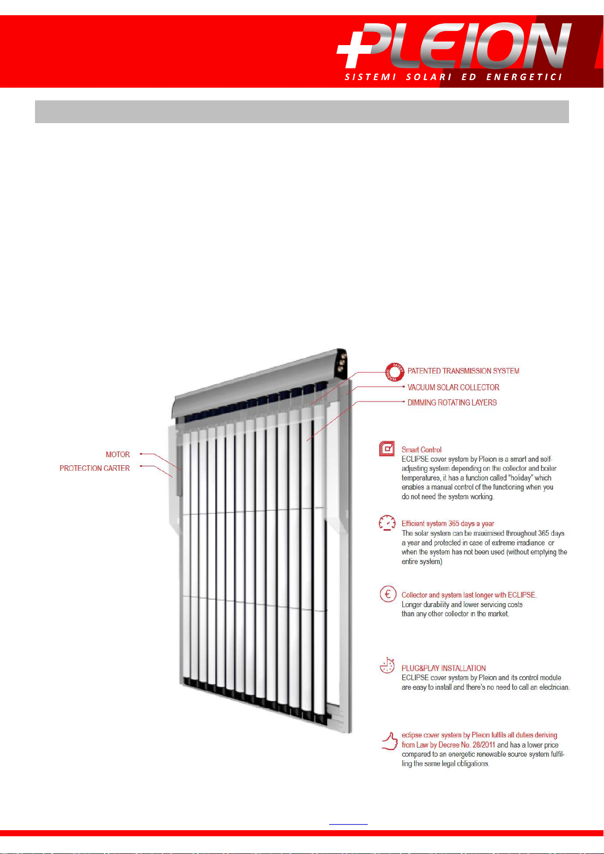
ECLIPSE COVER SYSTEM by PLEION is the first solar collector in the world presenting a smart revolutionary automatic covering
system able to control collector temperature and keep the highest level of efficiency of your Solar Thermal Plant 365 days a
year.
It’s easy to create a covering system, but rather hard to make a go-it-alone smart system allowing the best safety of all.
When designing ECLIPSE, our new solar collector, we have considered all the elements defining vacuum solar collector and we
targeted our energies towards creating something totally new, something completely different from what there was on the
market since then.
A brilliant idea: ECLIPSE does not resemble any other solar collector in the world.
ECLIPSE is optimised for top level performances. For the first time, a solar collector has been made to maximise thermal
efficiency.
Instead of using fans or other common solutions, in order to control over temperature, we have developed an innovative
covering system with rotating layers, controlled by a control unit with microprocessor.
PPlleeiioonn ss..rr..ll..
VViiaa VVeenneezziiaa,, 1111 -- 3377005533 CCeerreeaa -- VVeerroonnaa -- IIttaallyy -- TTeell.. ++3399 00444422 332200229955 -- FFaaxx ++3399 00444422 332277774422 -- wwwwww..pplleeiioonn..iitt -- iinnffoo@@pplleeiioonn..iitt
Page 2
Page 3
Solar collector ECLIPSE is composed of the following elements:
A. n.1 vacuum solar collector X-AIR 14;
B. n.1 covering system ECLIPSE.
A. Please go directly to Solar Collector X-AIR 14 installation and user’s manual, for technical features,
installation modes and its functioning.
B. Covering system ECLIPSE:
• It is a solar collector X-AIR 14 tool;
• it can be fully replaced, by re-enabling collector X-AIR 14 technical features;
• it can also modify solar collector X-AIR 14 performances.
PLEASE NOTE: solar collector X-AIR 14 is certified Solar Keymark (license number 011-
7S2431). Covering system ECLIPSE is not subject to certification.
Solar collector ECLIPSE can be installed with a tilt angle between 10° and 60°, as opposed to the solar
collector X-AIR 14.
RUNNING INSTRUCTIONS
Solar collector ECLIPSE is supplied already assembled.
For commissioning, you just have to do these following operations:
1. FIXING OF PLASTIC CARTER.
protection carter to the solar collector X-AIR 14 frame by further using hammer head screws as
included equipment.
2. ELECTRIC MOTOR WIRING.
For installations in windy areas or exposed sites, fix the plastic
Connect the electric motor of ECLIPSE system to the control unit.
For the wiring modes to control unit, please go to the wiring diagram on page 8 of this manual and
the specific use and installation supplied with the control unit equipment.
PPlleeiioonn ss..rr..ll..
VViiaa VVeenneezziiaa,, 1111 -- 3377005533 CCeerreeaa -- VVeerroonnaa -- IIttaallyy -- TTeell.. ++3399 00444422 332200229955 -- FFaaxx ++3399 00444422 332277774422 -- wwwwww..pplleeiioonn..iitt -- iinnffoo@@pplleeiioonn..iitt
Page 3
Page 4
FUNCTIONING
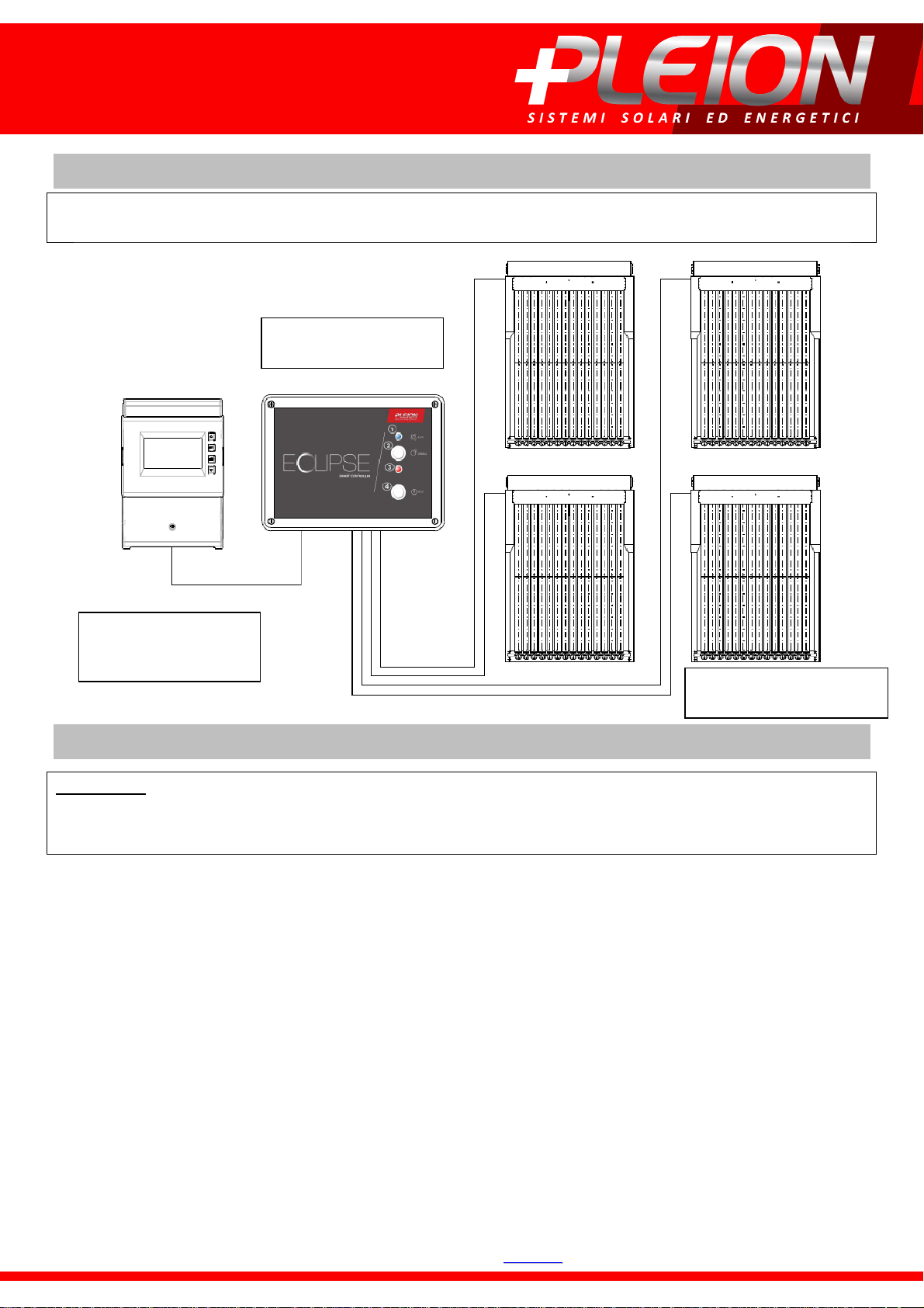
THE FUNCTIONING OF COLLECTOR ECLIPSE IS SUBJECT TO ITS CONNECTION TO A SOLAR JUNCTION BOX
(STECA MOD. 502 OR 503) AND CONTROL UNIT (CODE 1040812310).
Control unit for ECLIPSE
system
Solar controller
STECA (mod. 502 o 503)
or PB 404
ECLIPSE solar collectors
(from n.1 up to n.4)
INSTRUCTIONS FOR SAFETY
ATTENTION: PLEASE CAREFULLY READ THE FOLLOWING SAFETY INSTRUCTIONS BEFORE STARTING THE
INSTALLATION OF THIS APPLIANCE; THESE DATA ARE USEFUL TO PREVENT ELECTRICAL CONTACTS,
INJURIES AND OTHER ISSUES.
• After removing the packing, be sure that the appliance is intact.
• This machine has to be used only for its original designed purposes and the manufacturer cannot be
responsible for any of the damages caused by an improper use.
• Appliance installation must be carried out according to constructor’s instructions.
• A failure to observe those recommendations may compromise safety.
• All installation and service must be performed only by expert and qualified Personnel of a service
centre authorised by the Manufacturer.
• Before cleaning or making any other maintenance operation, you must disconnect the unit from the
mains grid. For maximum safety, it is recommended to remove all electrical connections.
• We highly recommend you to use only original spare parts.
• Failure to comply with the existing measures is likely to undermine safety and clear all benefits coming
from the equipment warranty.
• In case of troubles or errors during the installation or functioning, please address to your dealer or
directly to the manufacturer.
PPlleeiioonn ss..rr..ll..
VViiaa VVeenneezziiaa,, 1111 -- 3377005533 CCeerreeaa -- VVeerroonnaa -- IIttaallyy -- TTeell.. ++3399 00444422 332200229955 -- FFaaxx ++3399 00444422 332277774422 -- wwwwww..pplleeiioonn..iitt -- iinnffoo@@pplleeiioonn..iitt
Page 4
Page 5
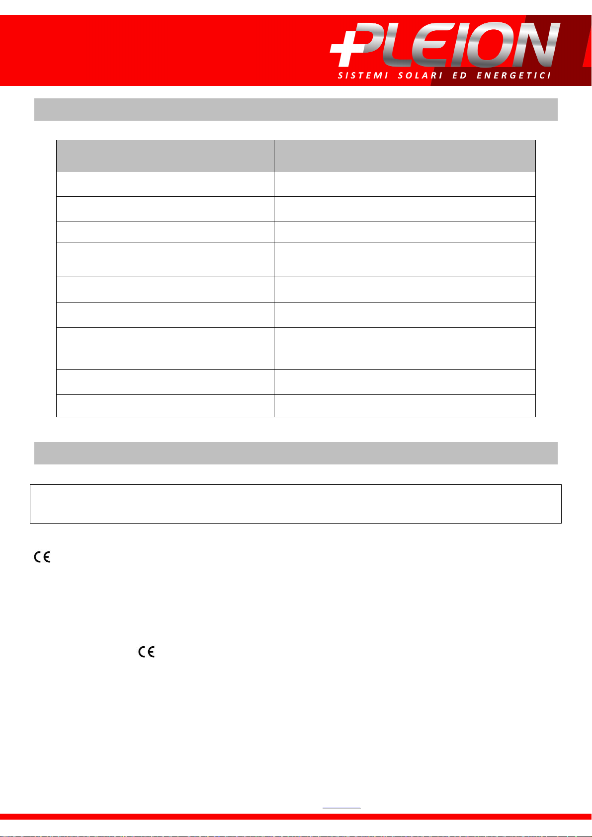
PARAMET
ER
VAL
UE
MOTOR TECHNICAL DATA
Supply voltage 24 Vdc
Electrical connection type three prong power cord – length 20 m
Control unit consumption in stand-by mode 5 W
Consumption of each single motor
connected in motion (for 3 seconds)
Power 30 Nm
Speed 12 r.p.m.
Protection level against external agents
(protection motor bowl not included)
External tubular diameter 50 mm
Total length (support panel not included) 486 mm
120 W
IP44
MOTOR TECHNICAL SPECIFICATIONS
EACH MOTOR IS SUPPLIED WITH A 20 MT POWER CABLE AND CONNECTION TO CONTROL UNIT;
SUCH LENGTH IS DIMENSIONED FOR A PROPER SYSTEM FUNCTIONING.
mark of control unit includes motor connections by using electric cable provided as standard
equipment.
ATTENTION. In case of modifications to the electric cables (for motors):
− Control unit mark ceases;
− Electrical connections must be redesigned according to new lengths;
− Lifeline protection level and system phase displacement must be checked again;
− a new certificate of compliance concerning the electric system must be issued by a qualified and
PPlleeiioonn ss..rr..ll..
VViiaa VVeenneezziiaa,, 1111 -- 3377005533 CCeerreeaa -- VVeerroonnaa -- IIttaallyy -- TTeell.. ++3399 00444422 332200229955 -- FFaaxx ++3399 00444422 332277774422 -- wwwwww..pplleeiioonn..iitt -- iinnffoo@@pplleeiioonn..iitt
authorised electrotechnical installer (Italian Ministerial Decree 37/2008).
Page 5
Page 6
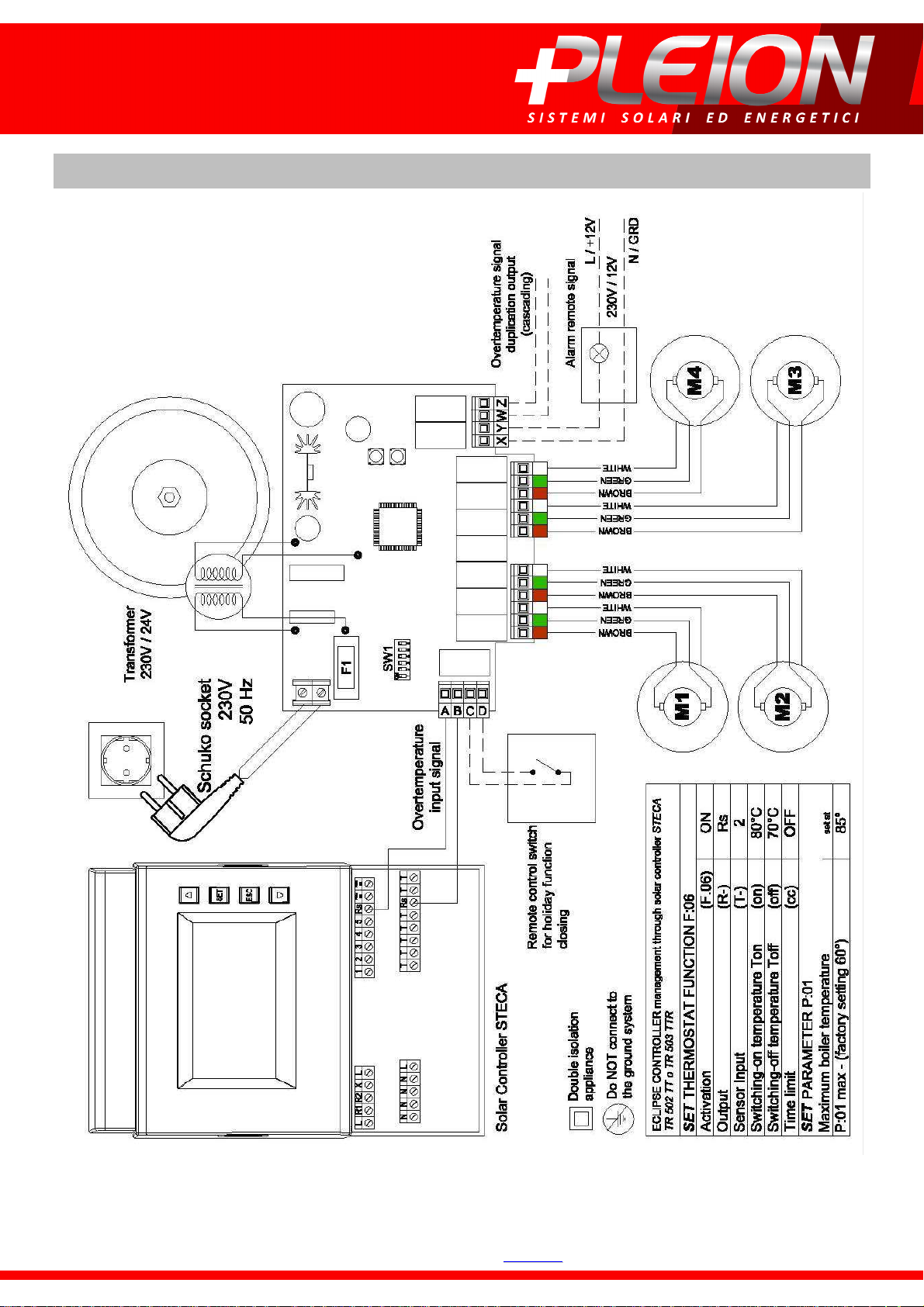
WIRING DIAGRAM TO CONTROL UNIT
PPlleeiioonn ss..rr..ll..
VViiaa VVeenneezziiaa,, 1111 -- 3377005533 CCeerreeaa -- VVeerroonnaa -- IIttaallyy -- TTeell.. ++3399 00444422 332200229955 -- FFaaxx ++3399 00444422 332277774422 -- wwwwww..pplleeiioonn..iitt -- iinnffoo@@pplleeiioonn..iitt
Page 6
Page 7
DECLARATION OF CONFORMITY
S.G. Elettronica s.r.l. - Via Ferrari, 28
30037 Scorzè Venezia – ITALY
P.IVA 02272310273
Tel. 041.5841973 / Fax 041.5841979
The company S.G. Elettronica s.r.l. declares that the items are in conformity with all technical regulations
related to products within the scope of application of the Community Directives 2006/95/CE, 2004/108/CE
and 99/5/CEE,
that is:
ETSI EN 301 489-3 V1.4.1:2002
ETSI EN 301 489-1 V1.8.1:2008
EN 300 220-1 V2.1.1:2006
ETSI EN 300 220 - 2 V2.1.2:2007-06
EN 50371 (2002)
EN 60950-1:2006 EN 60950-1/A11:2009
The declaration of incorporation for partly completed machinery (Directive 2006/42/CE,
Annex II- B)
The Manufacturer, S.G. Elettronica srl, declares that gearmotor for roller blinds and sun awnings of
HAD101 151 201 251 351 501 Classic model:
• it is intended for in corporation into a covering system for making a machine according to
Directive 2006/42/CE. Such machine cannot be put into service before being declared in
conformity with the provisions of Directive 2006/42/CE (Annex II-A).
• It is in compliance with the essential requirements applicable to the following regulations:
− machines directive 2006/42/CE (Annex I, Chap. 1);
− low voltage directive 2006/95/CE;
− Electromagnetic Compatibility Directive 2004/108/CE.
Year of manufacture: 2014
Scorzè, 10/10/2009
Signature of the legal representative: Sandro Zottino
PPlleeiioonn ss..rr..ll..
VViiaa VVeenneezziiaa,, 1111 -- 3377005533 CCeerreeaa -- VVeerroonnaa -- IIttaallyy -- TTeell.. ++3399 00444422 332200229955 -- FFaaxx ++3399 00444422 332277774422 -- wwwwww..pplleeiioonn..iitt -- iinnffoo@@pplleeiioonn..iitt
Page 7
Page 8
Pleion Srl
Via Venezia, 11 - 37053 Cerea Verona - Italy
Tel. +39 0442.320.295 - Fax +39 0442.327.742
[email protected] - www.pleion.it
Pleion Srl reserves the right to make modifications regarding technical, aesthetic and commercial details without any prior notice.
V e r s i o n
V e r s i o n 1111 .... 2222 o f
V e r s i o n V e r s i o n
PPlleeiioonn ss..rr..ll..
VViiaa VVeenneezziiaa,, 1111 -- 3377005533 CCeerreeaa -- VVeerroonnaa -- IIttaallyy -- TTeell.. ++3399 00444422 332200229955 -- FFaaxx ++3399 00444422 332277774422 -- wwwwww..pplleeiioonn..iitt -- iinnffoo@@pplleeiioonn..iitt
o f 2 4
2 4 //// 0000 6666 / 2 0 1 5
2 42 4
/ 2 0 1 5
/ 2 0 1 5/ 2 0 1 5
o fo f
C o d e
C o d e 1111 0000 3 0 9 9 1
C o d eC o d e
3 0 9 9 1 20
3 0 9 9 13 0 9 9 1
Page 8
2 0 1111
2 02 0
 Loading...