

Pledco VFI6, VFI8, VFI9.6, VFI12 User Manual

Pledco Broadcast Indoor
User ' s Manual
Version1.1
Pledco LED Display Ltd.

a
a
A Broadcast Indoor
A Broadcast Indoor
Broadcast Indoor
1
Table of Contents
1. Safety
1.1 Guidelines
1.2 Safety instructions
2. Series Tiles
2.1 Tile
2.2 display
3. Installation requirements
3.1 Mechanical requirements
3.2 Electrical requirements
3.3 System requirements for the Control software
4. Components of
display
4.1 Tile
4.2 Mechanical Components
4.3 Power Supply Unit
4.4 LDU
4.5 Video Processing Unit
4.6 Cables
4.7 Control software
4.8 Others
5. Installation
5.1 Preparing the back supporting structure
5.2 Mounting the extrusion frame
5.2.1 Assembling the extrusion frame
5.2.2 Mounting the frame
5.3 Fixing the display
5.4 Other mounting methods
6. Cabling display
6.1 Cabling an on-line display
6.2 Cabling an off-line display
6.3 Pixel limitations
7. Maintenance
7.1 Firmware update
7.1.1 LDU firmware update
7.1.2 Tile control board firmware update
7.2 Replacing a Tile of display
7.3 Replacing a Tile of a front serviced display
7.4 Replacing a Tile control board
7.5 Replacing a power supply
7.6 Replacing a LDU control board
8. Trouble shooting
9. Specifications
9.1 VFI series display specifications
9.2 Dimensions of display
9.3 Weights of display parts
10. Part Numbers of display parts
Broadcast Indoor
Broadcast Indoor
Broadcast Indoor
Broadcast Indoor
Broadcast Indoor
Broadcast Indoor
Broadcast Indoor
Broadcast Indoor
Broadcast Indoor
Broadcast Indoor
Broadcast Indoor
Broadcast Indoor
www.pledco.com
a
3
1. Safety
Before installing display, one is required to read this chapter carefully to obtain
important information as to how to prevent personal injury and to protect the display from damage
during installation.
Overview
§ Guidelines
§ Safety instructions
1.1 Guidelines
§ Before installing the display, make sure you have read the User’s Manual with full understanding.
§ Installation must be performed by authorized and qualified technical personnel only.
§ The installation site must be solid and without any chance of sinking, tumbling or falling. It must be at
the same time free of over-heat, radiation, pollution, corrosion or gas release.
§ Only use components provided by the Manufacturer or those approved or specified by the
Manufacturer during installation of series displays.
§ Do not modify and/or replicate any component or accessory without permit from the Manufacturer.
§ Always follow all installation instructions. Please contact the Manufacture if any problem arises.
Special attention should be paid to all “CAUTION” and “TIPS” mentioned in this User’s Manual which
respectively intends:
CAUTION: to draw operators’ attention to an important instruction or to remind them of what
might happen.
TIPS: to give advice on how to perform an operation better.
1.2 Safety instructions
Product care
§ All parts must be fully protected and packed in good order during transportation, storage, etc. No
external pressure shall be applied on them.
§ No part of the product can come into contact with rain before or during installation. Keep them in dry
and clean places.
§ All parts must be prevented from being trampled, stroke or dropped. Follow all instructions while
carrying or moving the parts. Otherwise the product can be subject to terminal damage.
Installation
§ Before installation, ensure that the supporting structure or frame has sufficient strength to hold the
display firm and safe.
§ For hoist installation, the operator must follow all instructions given in this User’s Manual, including
where the hoist brackets should be located, that the crane used must come with sufficient capability
to hoist the product, and that the operating ground must have the strength to sustain the crane, etc.
§ Most components of the product are heavy. Therefore high attention should be paid to personnel
safety during installation.
§ All connection bolts must be fastened firmly and securely.
Power
§ A display is to be powered by a 3-phase power with 5 lines. That is, it must come with
an independent neutral line and an independent ground line.
§ Provide the power and power supply circuits in accordance with the power consumption of the
display. All circuits must come with protection tubes and confirm with the local electrical safety
standards.
§ The LDU and PSU must be installed near the display. Cables from the LDU and PSU to the display
Broadcast Indoor
Broadcast Indoor
Broadcast Indoor
www.pledco.com
a
4
cannot be stretched or impaired. Power distribution from the PSU to the display cannot exceed what
is required by this User’s Manual.
§ The input voltage of display can be set at 120VAC or 220VAC. But ensure to set it
right before power connection.
§ Do not attempt to fix an impaired cable. Replace it with a new one.
§ A big current is produced the moment a display is powered on. Therefore an air breaker that can
sustain big currents should be used as the master power switch.
Grounding
§ displays must be grounded with an INDEPENDENT ground wire.
§ Displays to be installed independently from any architectural structure must be equipped with an
independent ground wire and, if necessary, a lightning rod. The down lead of the lightning rod should
be insulated with the frame of the display. Set the earth electrode of the lightning rod and that of the
ground wire away from each other.
Usage
§ LEDs on the display cannot be pressured at any time. Otherwise they can be damaged for good.
§ Follow the steps mentioned in this User’s Manual while cleaning the front side of the display. Only
soft clothing or brush, neutral detergent and water are to be applied to the display.
§ Power must be cut off before dismantling any part for maintenance.
Broadcast Indoor
Broadcast Indoor
www.pledco.com

a Broadcast Indoor
Broadcast Indoor
5
2.
Series Tiles
This chapter focuses on the main component of display---the Tiles.
Overview
§
Tile
§
Display
2.1 Tile
Tile overview
The front and back view of tile
The models VFI6, VFI8, VFI9.6 and VFI12 included in the series have tiles of the same
size but with different resolutions. Please see below:
Tile VFI6 VFI8 VFI9.6 VFI12
Pixel pitch 6mm 8mm 9.6mm 12mm
Resolution 64X48 48X36 40X30 32X24
Weight 2.8kg
Part Number
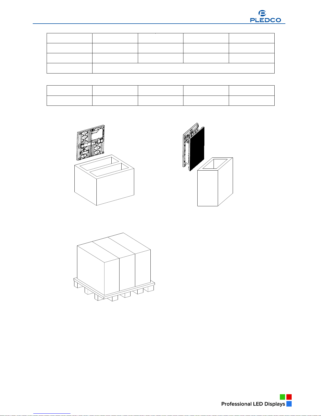
Tile VFI6 Tile VFI8 Tile VFI9.6 Tile VFI12 Tile
Part Number
The other series, the P series, uses Tiles integrated with a power supply.
The front and back view of P Tile
Broadcast Indoor
Broadcast Indoor
Broadcast Indoor
Broadcast Indoor
a Broadcast Indoor
Broadcast Indoor
Broadcast Indoor
Broadcast Indoor
a Broadcast Indoor
www.pledco.com
a
6
Parameters of
P series models
Tile VFI6P VFI8P VFI9.6P VFI12P
Pixel pitch 6mm 8mm 9.6mm 12mm
Resolution 64X48 48X36 40X30 32X24
Weight
Part Number
Tile VFI6P Tile VFI8P Tile VFI9.6P Tile VFI12P Tile
Part Number
Package of the series and the P series Tiles
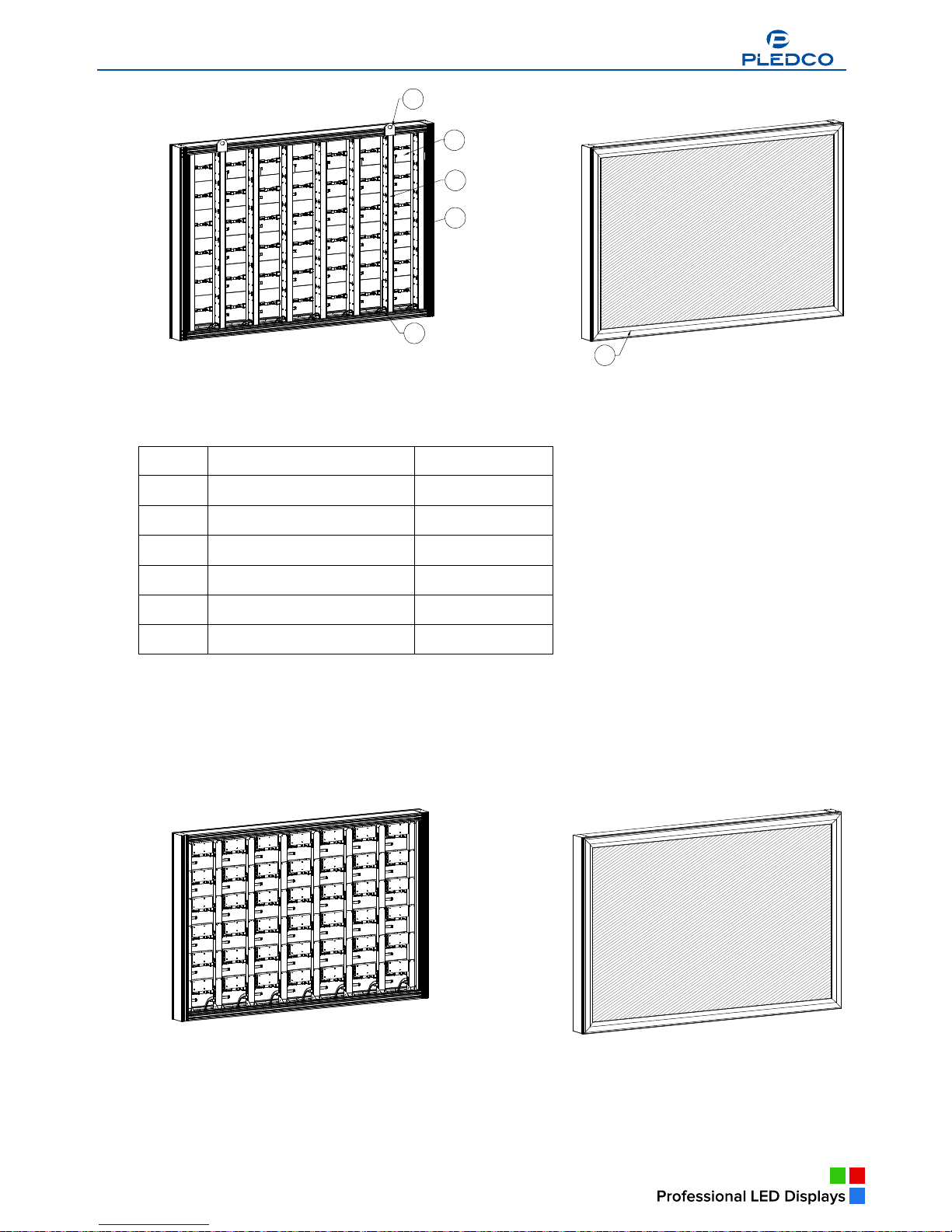
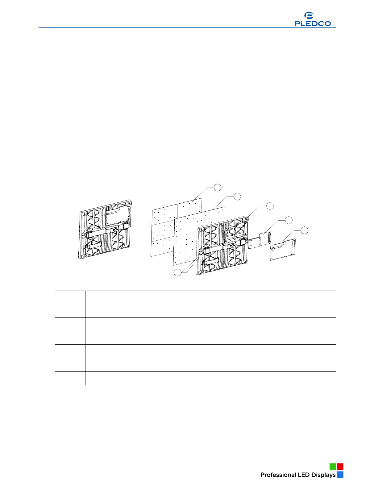
2.2 display
display overview
A display is made of a certain number of tiles and an extrusion frame. Thanks to its simple
structure, cabling and installation of the display can be done in a breeze.
View of display
Broadcast Indoor
Broadcast Indoor
Broadcast Indoor
Broadcast Indoor
Broadcast Indoor
Broadcast Indoor
Broadcast Indoor
www.pledco.com
7
6
1
5
3
4
2
Part Numbers
Parts Part Number
1 Tiles
2 Main extrusion
3 Cover extrusion
4 Column extrusion Module
5 Nut block
6 Eyebolt set
Given its module size, the size of display changes based on 384mm in its width and on
288mm in its height.
View of P series display
a
Broadcast Indoor
a
Broadcast Indoor
www.pledco.com

Broadcast Outdoor
a
A
Broadcast Indoor
9
3. Installation requirements
This chapter covers requirements for installation, power supply and the control system of
display.
Overview
§ Mechanical requirements
§ Electrical requirements
§ System requirements
3.1 Mechanical requirements
display comes with its own structural frame which makes installation simple and easy.
Besides, it requires a strong and reliable supporting frame at the back to hold the display firm.
Wherever this supporting frame is to be installed, on the ground, onto the pole or on a wall, attention
should be paid to the following few points:
1. The display should be installed in a place that allows a clear and complete view of the display.
2. The supporting frame has to be strong enough to prevent the display from tumbling.
3. The installation site must have the strength to withstand the total weight of the display plus its
structural frames
4. The display is meant for indoor use only. The ambient temperature, dust and ventilation,
esp. that at the back of the display must be considered when one is choosing the installation site.
A typical way of mounting display onto a wall:
3.2 Electrical requirements
Power requirements
§ A display works on AC 200-240V, 50~60Hz. Each column of the display has an
independent power supply circuit and can thus be powered by electricity from different phases.
§ When the max. power consumption of display is less than 3KW, the display can
be powered by single-phase power supply circuits which include a live, neutral and ground wire.
Each circuit is controlled by an independent air-break switch.
§ But if the maximum consumption of the display is over 3KW, it should be powered by 3-phase
power supply circuits c/w a live, neutral and ground wire. The 3-phase power distributes power to
tiles of each column on an average level. A PSU (power supply unit) is used to control the power.
§ The block can also be powered by AC100-125V, 50~60Hz power supplies. But this
needs to be specified in the production order so that it can be pre-set before going out of factory.
Broadcast Indoor
Broadcast Indoor
Broadcast Indoor
Broadcast Indoor
a
Broadcast Indoor
www.pledco.com
10
Grounding
The display shall be grounded at the installation site. If the existing power supply circuit
cannot provide a good ground wire or does not even have one, it ’s a must to set or reset a reliable
ground wire for the display. Good grounding will enable the display to work properly and can prevent it
from being disturbed by surge.
3.3 System requirements for the Control software
When the Windows System is in question:
PC System requirements:
§ CPU Pentium IV or equivalent, 2.4GHz
§ 1 GB DDR RAM
§ Free hard disk space 300MB
§ Resolution 1280x1024 with 32M video memory
§ DVI port
§ Ethernet connection
§ Windows XP Professional or Windows Vista
Broadcast Indoor
www.pledco.com
Broadcast Outdoor
a
11
4. Components of a display
This chapter continues to introduce other components that make up of display.
Overview
§ Tile
§ Mechanical Components
§ Power Supply Unit (PSU)
§ Logic Distribution Unit (LDU)
§ Video Processor Unit (VPU)
§ Cables
§ Control software
§ Others
4.1
Tile
Introduction to the Tile
The Tile is the basic display unit of a display. The Tile is composed of an
LED display board, a mask, a control board and some locks. At the back of the Tile is a connector that
integrates the signal and DC power input.
View of Tile
1
6
5
4
3
2
Parts and Part Numbers
Parts Part Numbers Remark
1 Mask
2 PCB
3 Tile base
4 Control Board
5 Cover plate
6 Lock head
The P series Tile includes an extra covered power box. Besides, the P series Tile has independent
signal connectors and AC input connectors.
The view of P series Tile
Broadcast Indoor
Broadcast Indoor
Broadcast Indoor
Broadcast Indoor
Broadcast Indoor
a
Broadcast Indoor
a
Broadcast Indoor
www.pledco.com
Broadcast Indoor

12
1
7
6
5
3
2
4
Parts and Part Numbers
Parts Part Numbers Remark
1 Mask
2 PCB
3 Tile base
4 Control Board
5 Cover plate
6 Power Supply
7 Power cover
4.2 Mechanical Components
Besides the tile, there are some structural components that help make up display.
The main extrusion is the structural frame of display, while the cover extrusion is used
as a decorative frame to the front of the display. The pole structure is the supporting frame where tiles
are to be mounted. It also comes with switch power supplies, power and signal circuits and connectors
to the tiles.
3
4
1
2
a
Broadcast Indoor
a
Broadcast Indoor
www.pledco.com

13
Eyebolts are used for hoist installation of the display. They can be removed after installation.
Parts and Part Numbers
Parts Part Numbers Remark
1 Cover extrusion
2 Main extrusion
3 Column extrusion Module
4 Signal connector
Similarly, the P series display uses the main extrusion and the cover extrusion as its main
structural frame. But there is no power supply in its pole structure. Inside it there are only AC power
supply cables and signal cables and their connectors.
Parts and Part Numbers
Parts Part Numbers Remark
1 Cover extrusion
2 Main extrusion
3 Column extrusion Module
4 Column pole
4.3 Power Supply Unit (PSU)
The PSU, short for Power Supply Unit, is the power control center for display. Each
output channel of the PSU controls one column of tiles of a display. The PSU is also inbuilt with a surge
protector to prevent the display from being disturbed by lighting.
But if the power consumption of a display is not high, an air-break switch can be used in place of a PSU.
a
Broadcast Indoor
Broadcast Indoor
www.pledco.com
 Loading...