

Page 1

LED Display
LDU3000 (A) User’s Manual
VER: V1.1
Page 2

Copyright
All rights reserved. No part of this document may be copied, reproduced,
translated, or recorded via any means without the prior written consent of
PLEDCO™
PLEDCO™ may make improvements and/or changes to the product(s) and/or
the program(s) described in this publication at any time without notice. This
publication could contain technical inaccuracies or typographical errors. Changes
are periodically made to the information in this publication; these changes are
incorporated in new editions of this publication.
Page 2 of 20
Page 3

Brief Introduction .......................................................................................................................................... 4
Chapter I: Functions & Installation of LDU3000 (A). ..................................................................................... 5
1. Functions of LDU3000 (A) ................................................................................................................. 5
2. Installation of LDU3000A .................................................................................................................. 7
Chapter II: Wiring & Application of LDU3000 (A) ......................................................................................... 9
1. Signal Diagram of PLEDCO Screen system ........................................................................................ 9
2. LDU3000/LDU3000A | Connect via receiving card ......................................................................... 10
3. LUD3000/LDU3000A - Connection to Light Sensor......................................................................... 12
4. LDU3000/A-Connection and Communication to Computer ........................................................... 13
4.1 RS232 ...................................................................................................................................... 14
4.2 Communication via RS485 ...................................................................................................... 15
4.3 Communication via Ethernet .................................................................................................. 15
5. Connecting VPU3000 and LDU3000 via Optical Fiber ..................................................................... 15
Chapter III: Maintenance of LDU3000 (A) ................................................................................................... 16
1. Backup LDU3000 to computer ........................................................................................................ 16
2. Restoration and Maintenance ........................................................................................................ 16
2.1.1 Replacement of LDU3000 ................................................................................................... 16
2.1.2 Replace mainboard inside LDU. .......................................................................................... 16
2.1.3 Configure Parameters ......................................................................................................... 16
2.1.4 Press Restore ....................................................................................................................... 16
2.1.5 Switch off and restart the power supply of LDU. ................................................................ 16
2.1.6 Check if screen is working normally. ................................................................................... 16
3. Replacement of Optical Fiber and Optical Fiber Plug ................................................................. 17
Appendix ..................................................................................................................................................... 19
1. Explanation for QS5800 in LDU3000HUB ........................................................................................ 19
1.1 Layout of QS5800 .................................................................................................................... 19
1.2 Functions of Interfaces............................................................................................................ 19
1.3 Functions of Dip Switch SW1 .................................................................................................. 20
2. Device and Parts.............................................................................................................................. 20
Page 3 of 20
Page 4

Brief Introduction
Chapter I: Functions & Installation of LDU3000 (A), covering functions
and installation of LDU3000 (A)
Chapter II: Connection & Application of LDU3000 (A) explains offline
connections and synchronous connection.
Chapter III: Maintenance of LDU3000 (A), explains backup,
maintenance and functions of control boards.
Page 4 of 20
Page 5
Chapter I: Functions & Installation of LDU3000 (A).
1. Functions of LDU3000 (A)
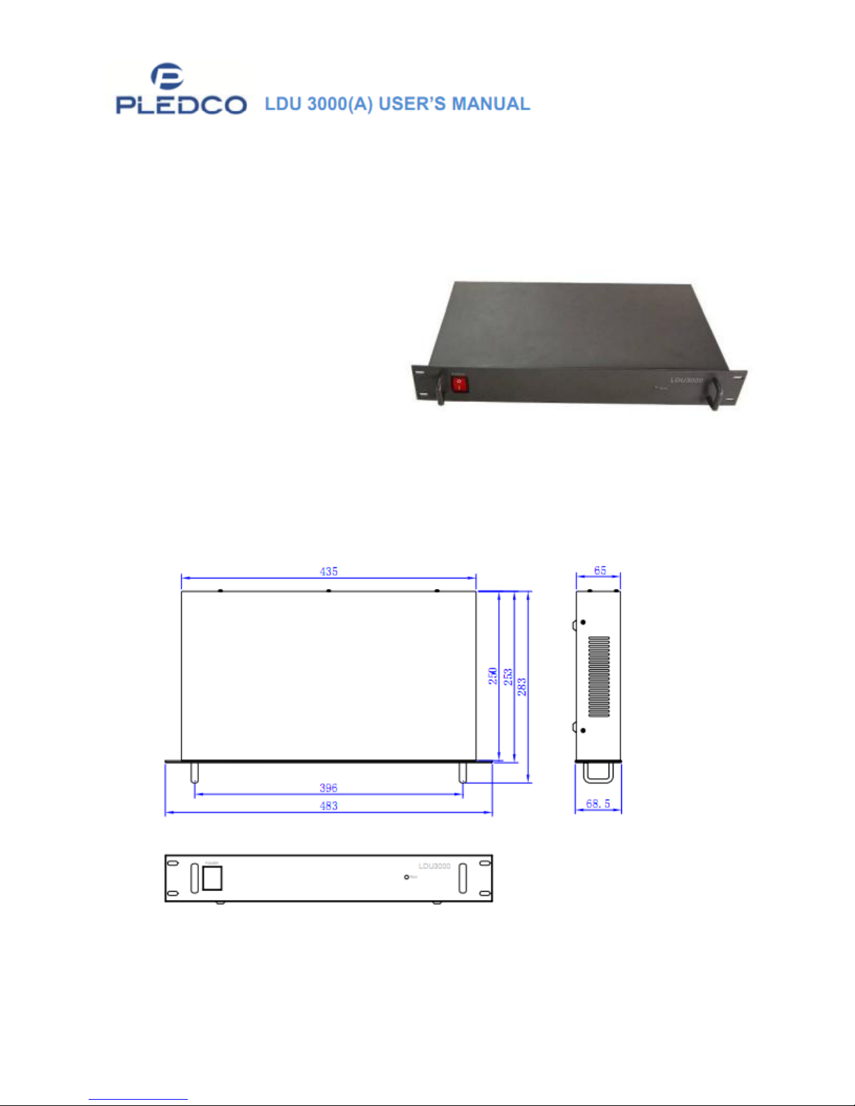
LDU3000: for indoor
applications and fast
installation of moveable
Page 5 of 20
Page 6
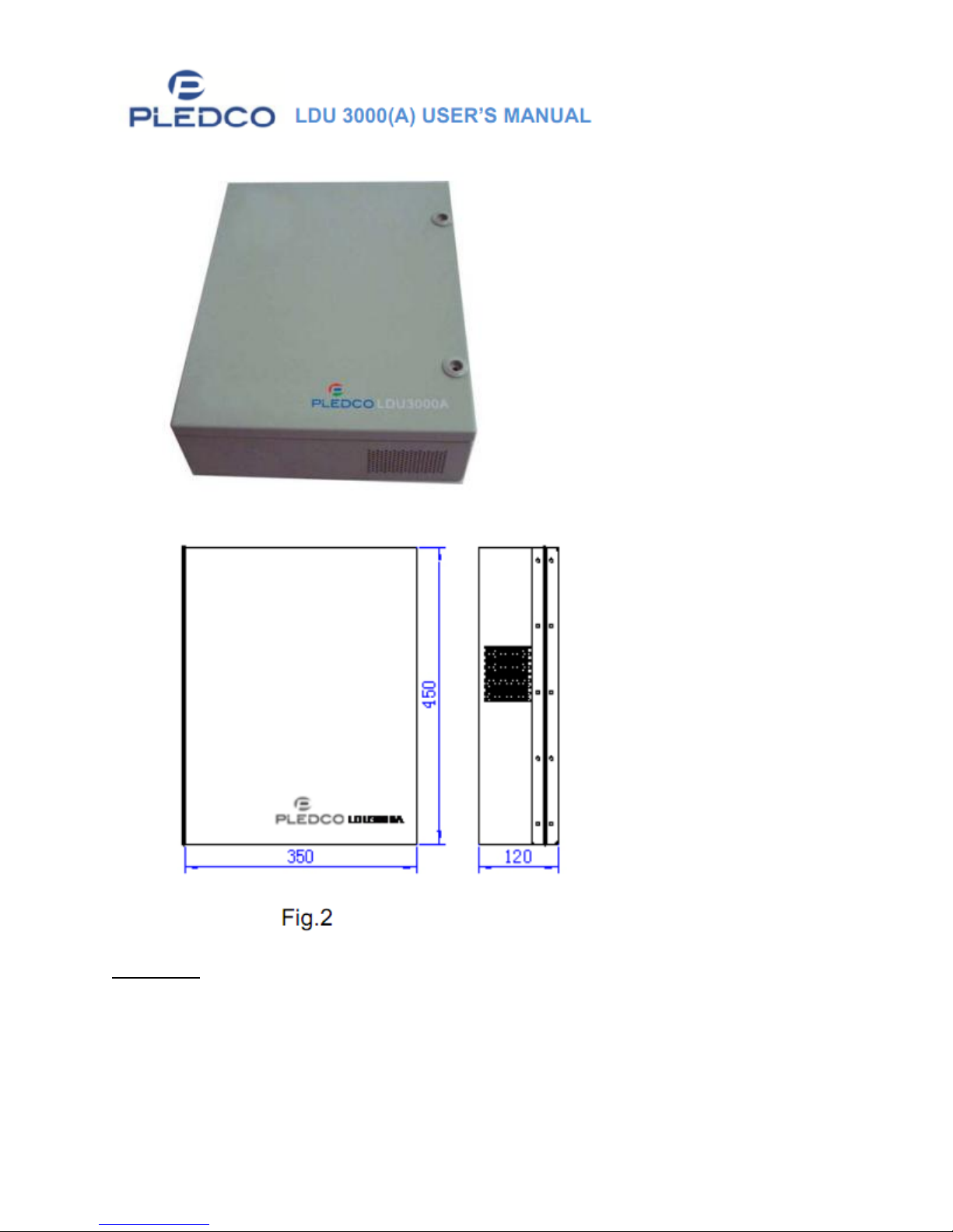
LED screensLDU3000A:For outdoor use, with IP level of 54.
Fig. 1
Functions
MAX: 16 signal outputs
Connect to VPU3000 to form a synchronous playing system
Use alone as an offline system
MAX resolution: 1024X768
Page 6 of 20
Page 7
Communications:
Fiber Optic (for synchronous system), Ethernet (Offline), RS232 (for
updating), RS485
Connects to Light Sensor for examining real-time brightness.
Adjust the brightness of screen automatically.
2. Installation of LDU3000A
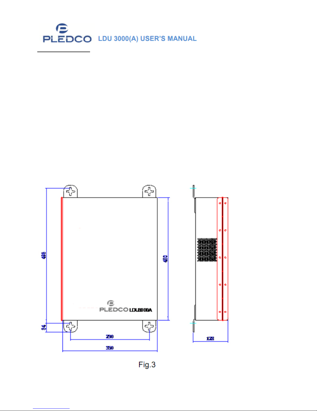
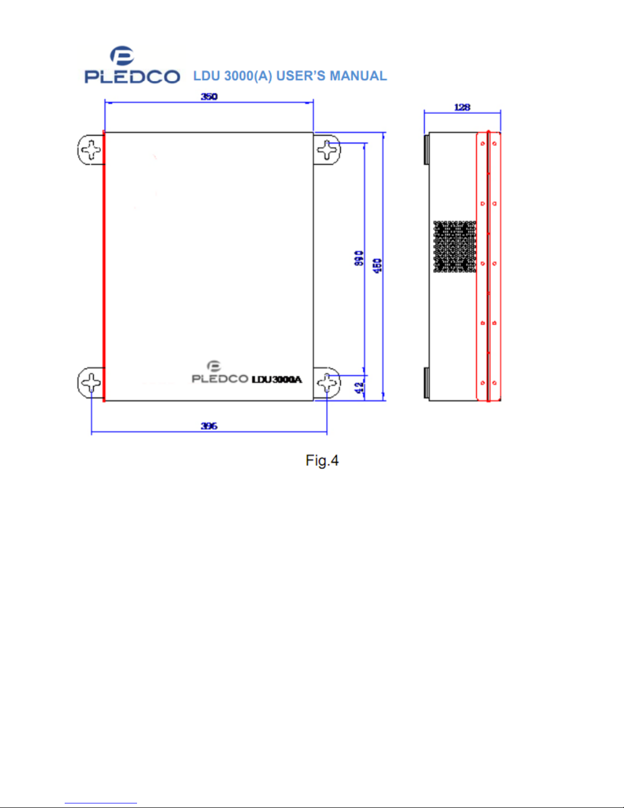
LDU3000A is waterproof and suitable for outdoor installation. LDU3000A can be
installed by the sockets as seen in Figure 3 and 4. LDU3000A can be fixed to
frameworks by the following dimensions.
Page 7 of 20
Page 8
Page 8 of 20
Page 9
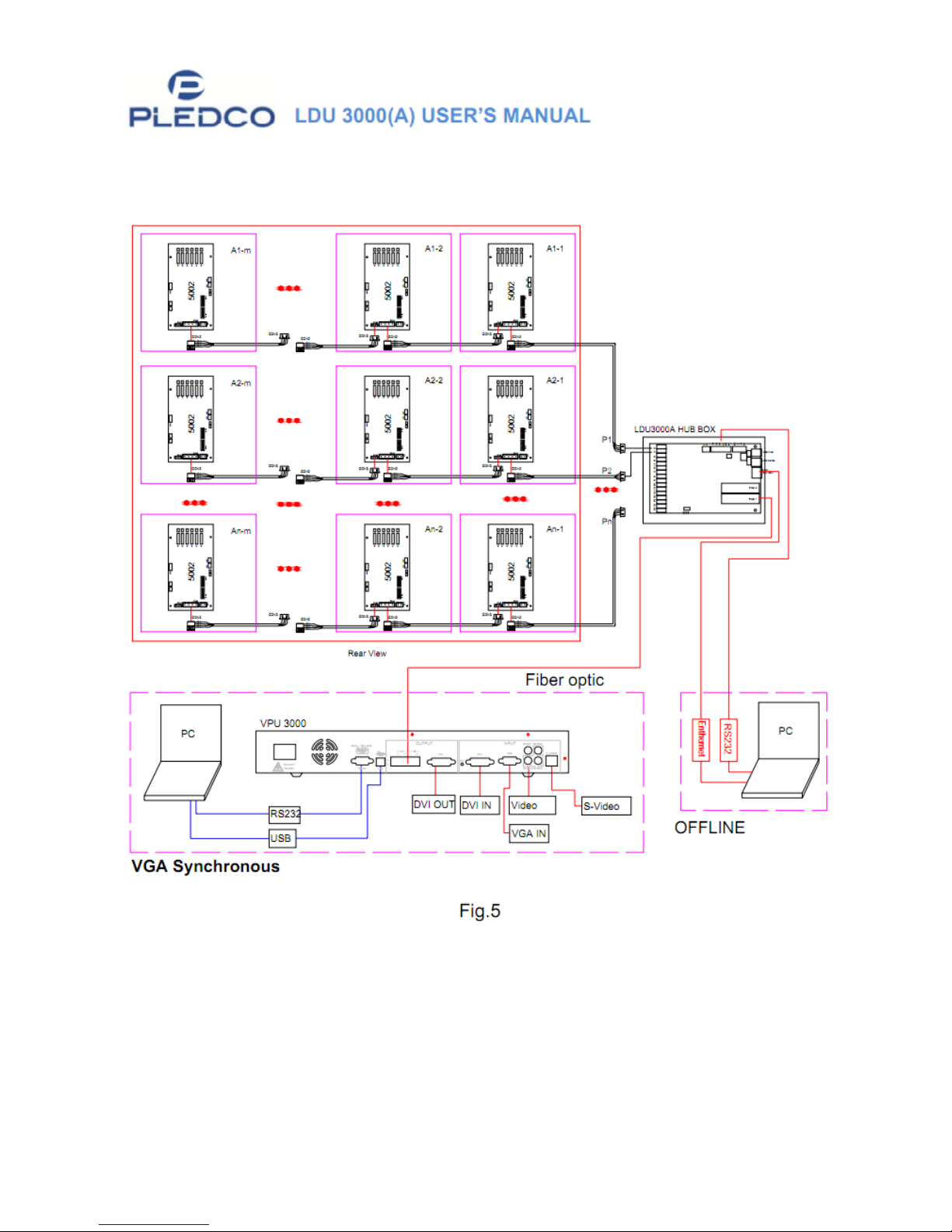
Chapter II: Wiring & Application of LDU3000 (A)
1. Signal Diagram of PLEDCO Screen system
Page 9 of 20
Page 10
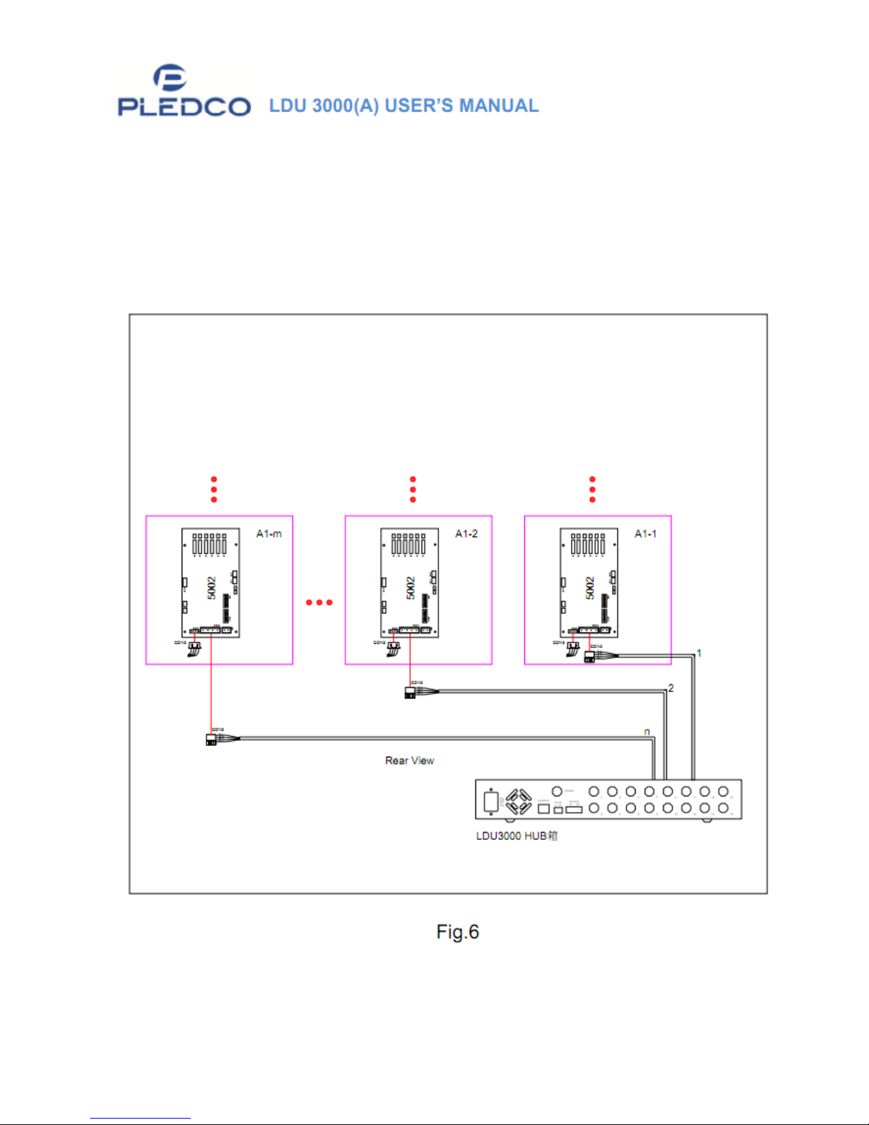
2. LDU3000/LDU3000A | Connect via receiving card
A) Starting from the right …
i. A1-1 connects to the LDU3000’s Port 1
ii. A1-2 connects to Port 2.
iii. Continue sequentially for the remainder cabinets.
Page 10 of 20
Page 11
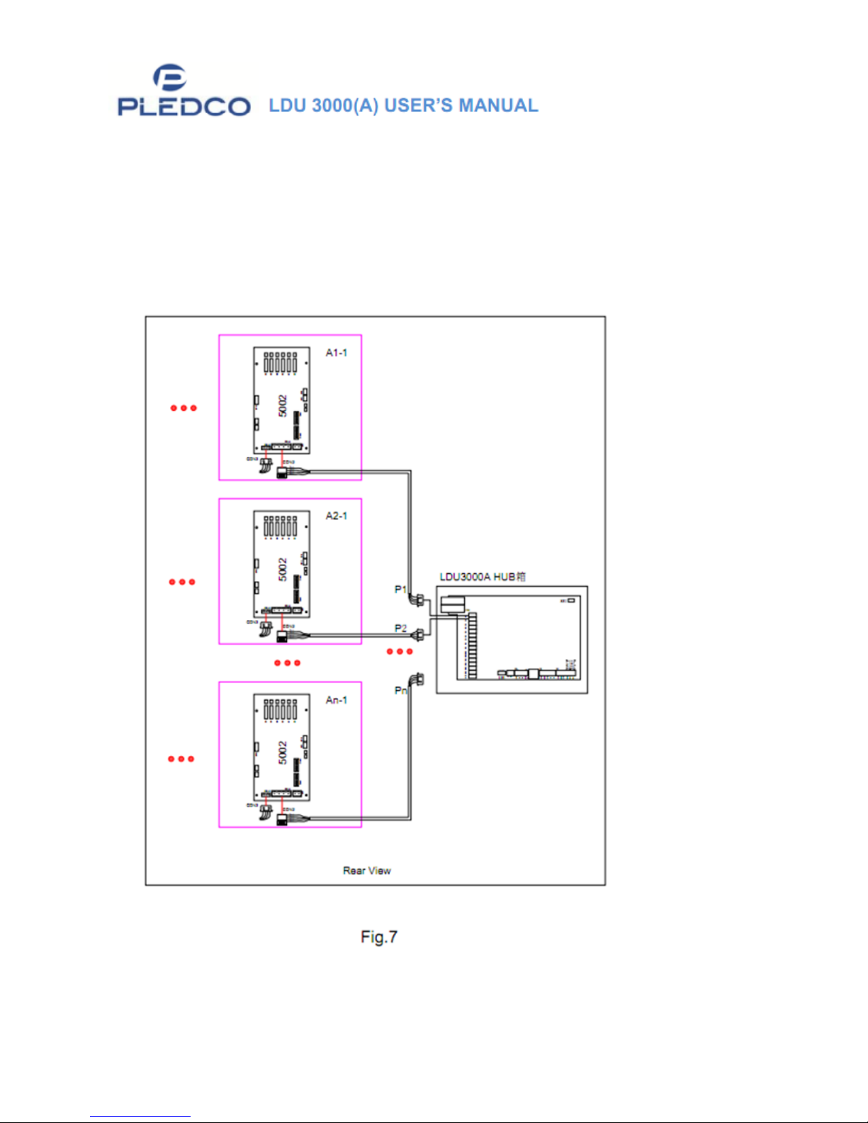
B) When the LDU3000A HUB is connected to the display, A1-1 cabinet should
be connected to Port 1 of the QS5800, which is located inside the
LDU3000A Hub.
i. Cabinet A2-1 should connect to Port 2
ii. Continue sequentially for the remainder cabinets.
Note: Refer to QS5800 in the Appendix.
Page 11 of 20
Page 12
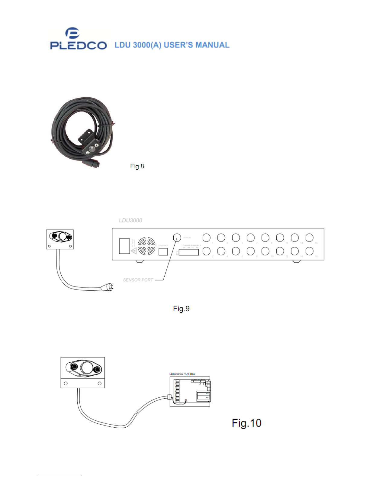
3. LUD3000/LDU3000A - Connection to Light Sensor
A) Light Sensor
B) Connect the Light Sensor directly to the Sensor Port at the back of
LDU3000, see the picture below:
C) Connect the Light Sensor directly to the Sensor CON interface on the
QS5800 main board in the LDU3000A, see the picture below:
Page 12 of 20
Page 13
4. LDU3000/A-Connection and Communication to Computer
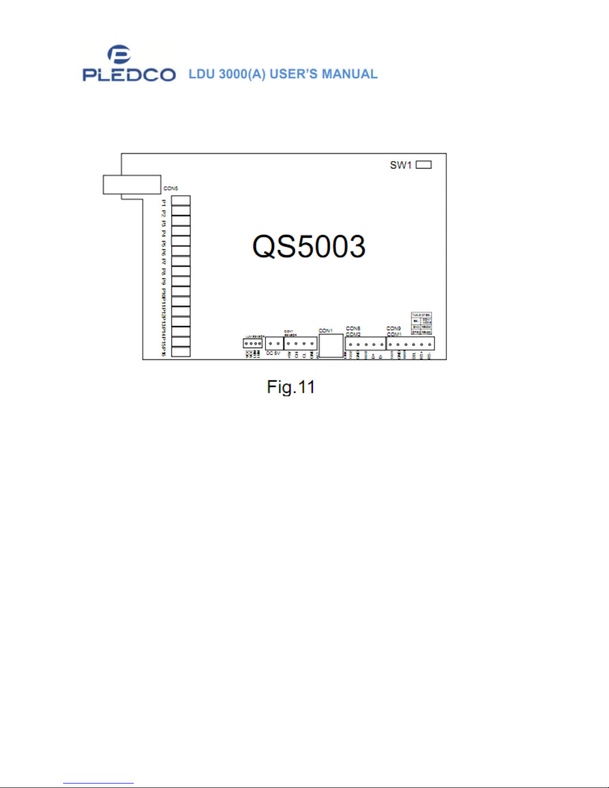
Independent COM interfaces are on the QS5800 main board inside the
LDU3000/A.
COM1: RS232 or RS485;
If SEL (connecting to GND) is selected, the communication
should be RS232
If SEL is suspended, the communication be RS485
RS232 and RS485 cannot be used together.
Ethernet Port is inside QS5800 main board inside the LDU3000/A.
CON1: Ethernet interface
2 USB Ports
Note: Continue reading for in-depth explanation of the QS5800.
Page 13 of 20
Page 14
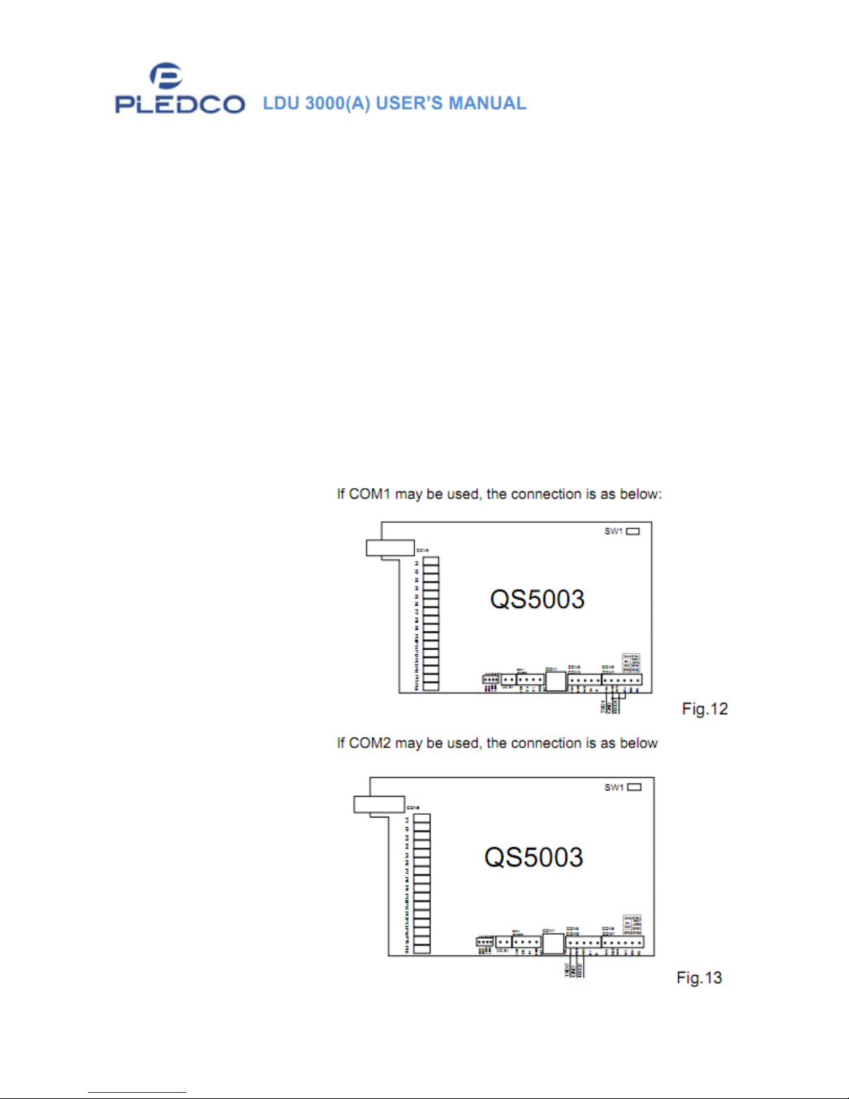
4.1 RS232
A) When the system is offline, RS232 cable may be used to communicate with
QS5800 to change screen content or settings.
B) When using the VGA synchronous system, only RS232 cable should be used
to update the CPU of QS5800.
Note: Whether offline or synchronous system, the communication of RS232 must
be considered while doing the wiring, since RS232 has a short communication
distance. RS232 interfaces should be prepared at the bottom of the screen (or
bottom of supporting columns) while doing the wiring, this will allow users to
easily connect to a laptop.
C) RS232 Connection:
Page 14 of 20
Page 15
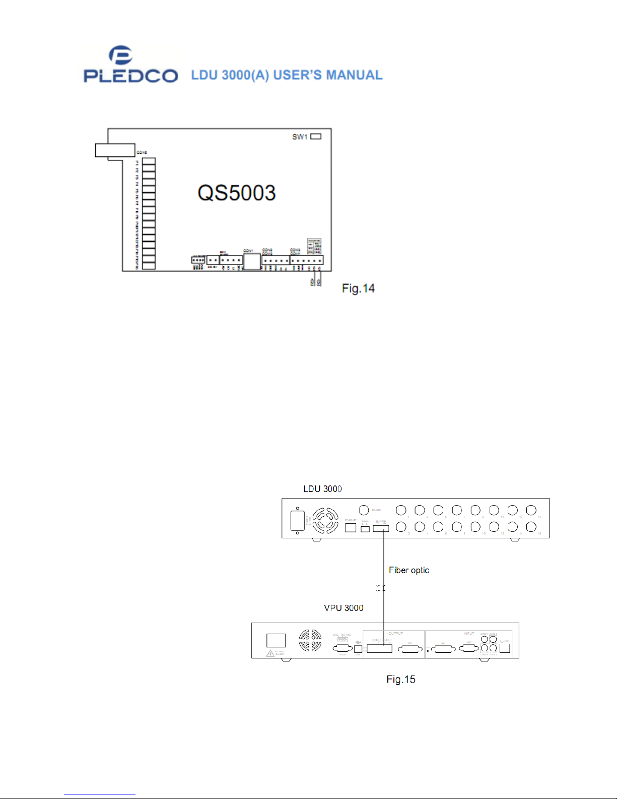
4.2 Communication via RS485
4.3 Communication via Ethernet
A. Where the system is offline, Ethernet cable may be used to connect QS5800 main board, inside
the LDU3000A, to COM1 interface.
5. Connecting VPU3000 and LDU3000 via Optical Fiber
There two optical fiber interfaces in the LDU:
1. Data transmission
2. Overheating backup
“To ensure the screen door
from opening and closing,
the wire and cables must
follow along the suction
canals at the bottom of the
cabinets …”
Page 15 of 20
Page 16

Chapter III: Maintenance of LDU3000 (A)
1. Backup LDU3000 to computer
PLEDCO’S Tools Program should be used when backing up LDU3000 to a
computer.
For operation details, please refer to PLEDCO Tools User Manual.
Once Tool Program is opened begin LDU information saving process.
A) Select Tool\Backup LDU date\Save to computer.
B) Select a location for saving backup file and name the file to be saved.
C) Press “Backup” button to start backing up.
D) Wait until 100% completion.
2. Restoration and Maintenance
2.1.1 Replacement of LDU3000
2.1.2 Replace main board inside LDU.
Replace with a new LDU main board, and connect to power supply,
communication cables, and optic fiber.
Double -check all connections are the same as before.
2.1.3 Configure Parameters
Open PLEDCO Tools and select Tool\Recover\Recover from
computer
Confirm the prompting message
Open the LDU backup file from your computer
o For example, backup.LDU
2.1.4 Press Restore
Begin back up and wait for 100% completion.
You can follow the same operations to update all the LDU(s) (if
there are many LDUs).
2.1.5 Switch off and restart the power supply of LDU.
2.1.6 Check if screen is working normally.
Page 16 of 20
Page 17
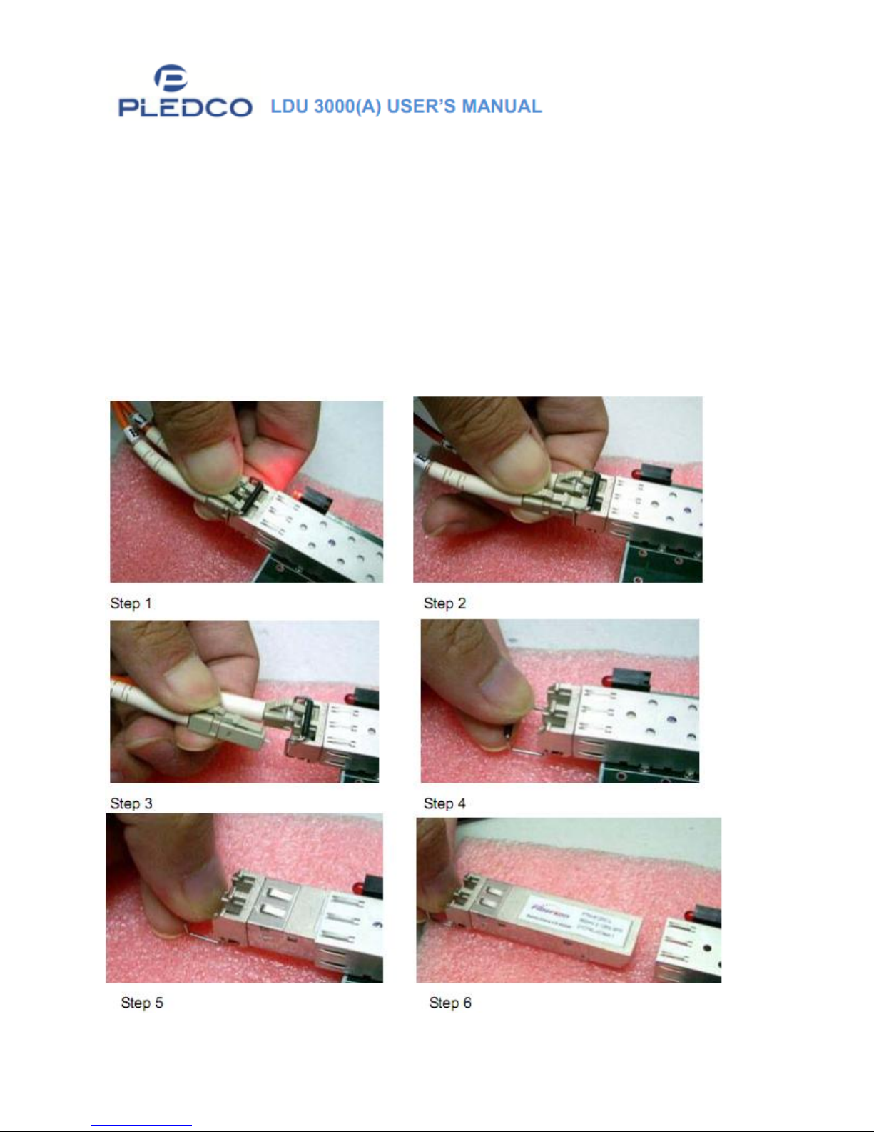
3. Replacement of Optical Fiber and Optical Fiber Plug
Optical Fiber should be multimode.
For outdoor use, the optical fiber is usually fusion spliced by experts on-site
and does not need to be changed.
For indoor use, optical fiber is usually grafted in the optical fiber connector.
o Be careful when inserting or unplugging the optical fiber head, not to
damage it.
Review the following steps when unplugging the optical fiber:
Page 17 of 20
Page 18
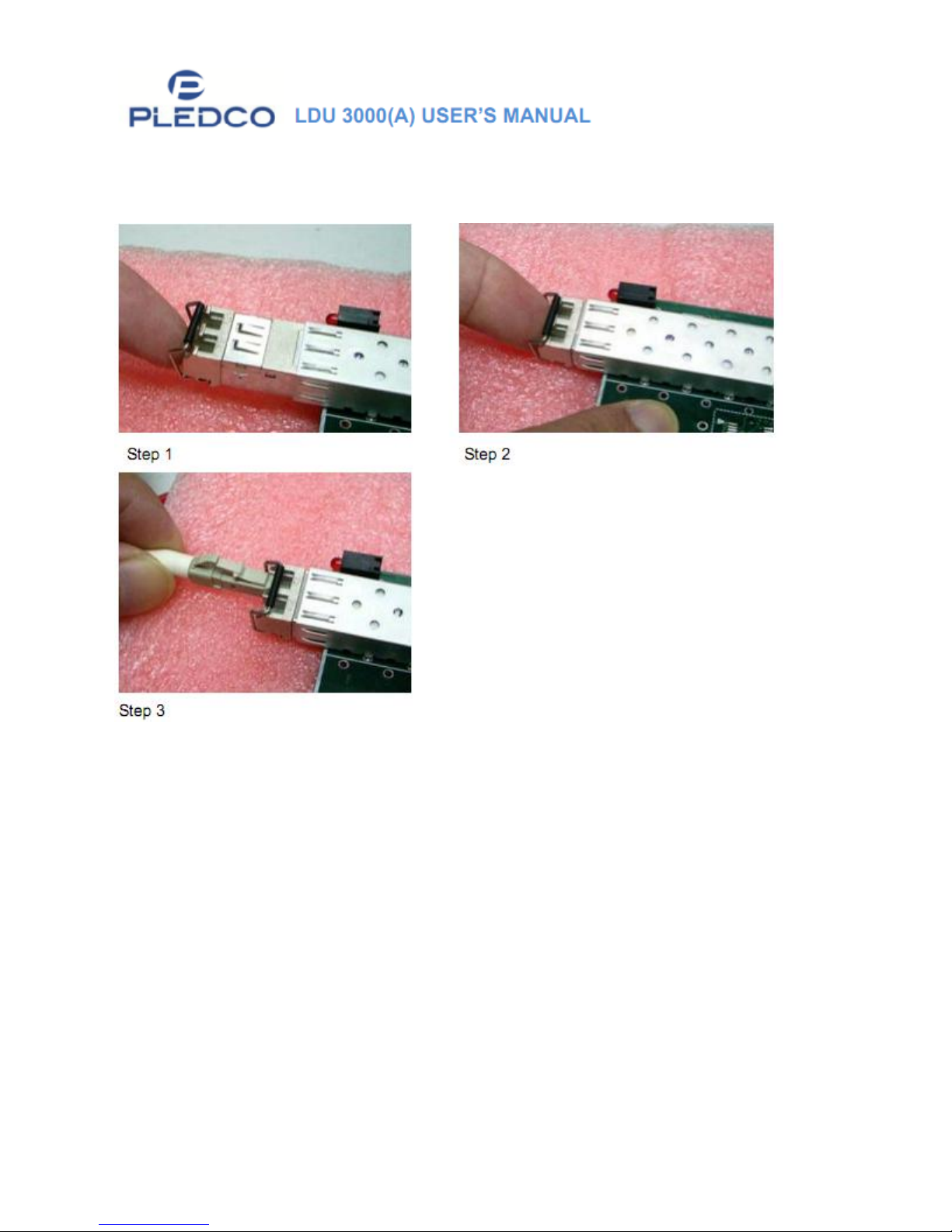
Review the following steps when inserting the optical fiber:
Page 18 of 20
Page 19
Appendix
1. Explanation for QS5800 in LDU3000HUB
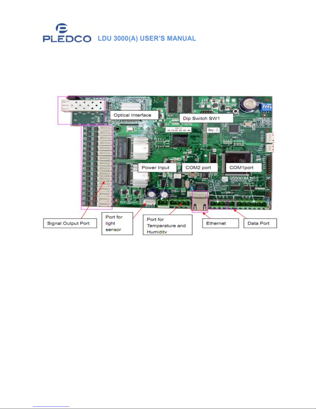
1.1 Layout of QS5800
1.2 Functions of Interfaces
Ports 1-16: Data output interfaces, respectively connected to input of the
first cabinet for each line of the screen. Counting from top to bottom as
follows … P1, P2, and P3…
COM1: RS232 or RS485;
o If SEL (connecting to GND) is selected, the communication should be
RS232
o If SEL is suspended, it should be RS485.
COM 2: RS232COM 7: Sensor CAN bus interface for light sensor,
temperature sensor, humidity sensor.
Page 19 of 20
Page 20
1.3 Functions of Dip Switch SW1
DIP1~DIP4=AD (4 ….0) Address Range:0~7
Note: “0” means ON, “1” means OFF.
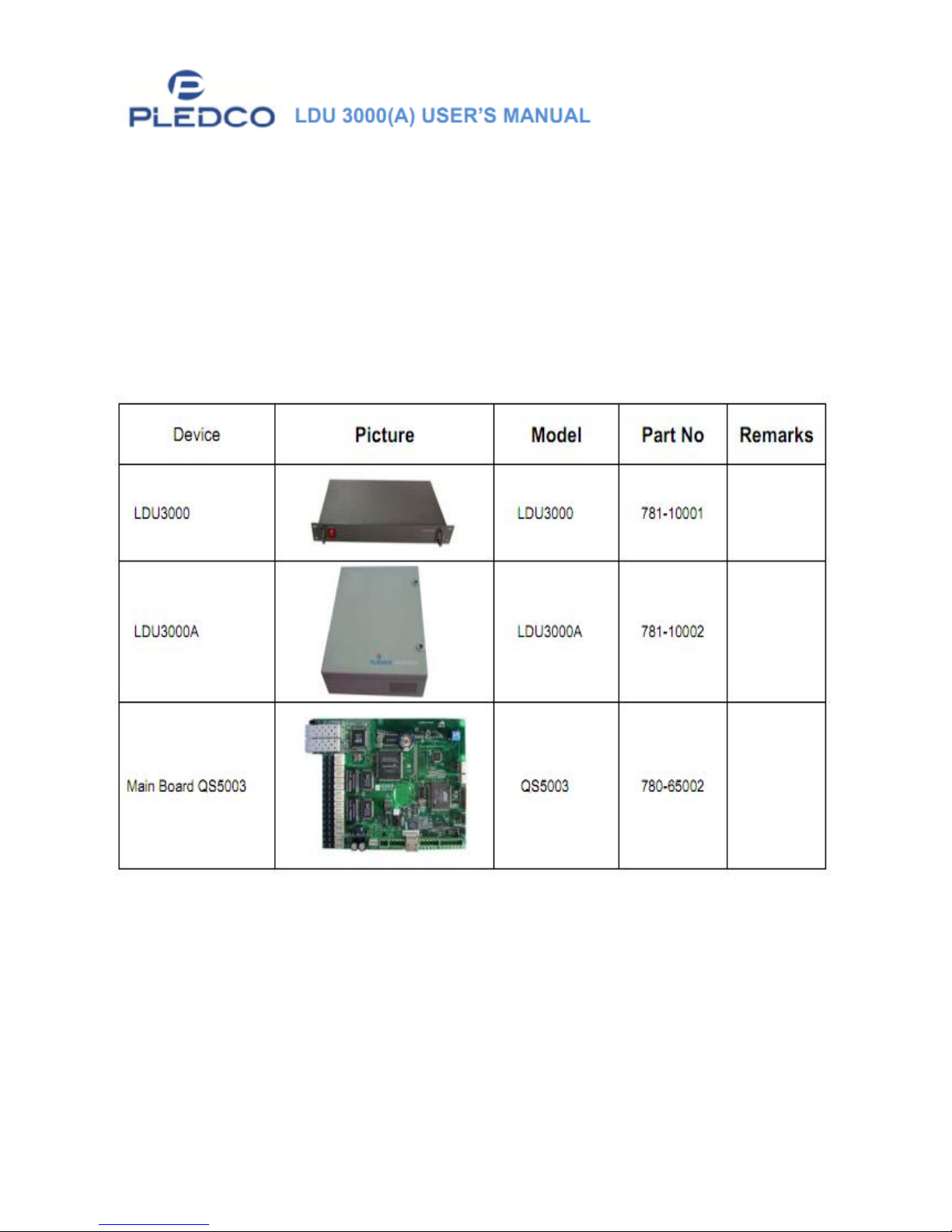
2. Device and Parts
Page 20 of 20
 Loading...