

Pleasurecraft marine Pleasurecraft 302/2A, Pleasurecraft 351/4, Pleasurecraft 302/4 Owner's Manual


STATEMENT OF LIMITED WARRANTY
The Pleasurecraft Marine Engine Co warrants its new products to be free from defects in material and workmanship under normal use and
service conditions, to the first registered owner or user. Covered under the Pleasurecraft warranty are all Pleasurecraft supplied components, except for
those components warranted by Pleasurecraft Suppliers. The obligation of Pleasurecraft shall be limited to the repair or replacement, at its option, of
any part or parts which have failed during the period of warranty and which Pleasurecraft's examination shall disclose to have failed due to defective
material and/or workmanship.
WARRANTY PERIOD
This warranty shall be valid to the first registered owner or user only, for the period specified below.
All components, other than those itemized below, are warrantied for a period of one (1) year from the date of delivery to the first registered
owner, or until the expiration of 200 hours of operation, whichever occurs first, in non-commercial use. In case of commercial use, said warranty shall
be for a period of six (6) months from the date of delivery to the first user or registered owner or until the expiration of 200 hours of use or whichever
occurs first.
Exceptions to the one (1) year/200 hour warranty;
(A) Water pump impellers not covered by warranty.
(B) Electrical system and fuel system warranty is for a period of 90 days from the date of delivery or first use.
(C) Seals, gaskets, o-rings and other material affected by time are not covered by this warranty if their effectiveness is reduced by an
extended storage period prior to sale and/or use.
(D) Components supplied by the Ford Motor Co. are warrantied by the Industrial Engine Division of the Ford Motor Co.
MANNER OF PERFORMANCE OF WARRANTY
Service under the terms of this warranty must be performed by an authorized Pleasurecraft Marine dealer or distributor without charge for
replacement parts or established flat rate labor, excepting miscellaneous items not considered as warranty defects, such as, but not limited to,
lubricants, spark plugs, points, and other items which are normally frequently replaced as part of normal maintenance. Charges for additional nonwarranty work and/or additional dealer charges relative to warranty work in excess of flat rate must be paid for by the owner.
Prior authorization in writing must be obtained for any warranty repairs over $50.00 and in all cases where customer fails to establish purchase
and warranty expiration date with the Warranty Identification Card sent the owner upon receipt of his warranty registration form by Pleasurecraft. The
product warranty is not in effect and, therefore, cannot be honored until the product purchase date can be confirmed by Pleasurecraft.
FAILURE EXCLUDED FROM WARRANTY
This Warranty will not apply to any failure which results from accidents, sinking, fire, neglect, abuse, or abnormal service, such as racing,
towing or operating in water of insufficient depth, or to any failure resulting from improper installation, improper adjustments or improper delivery
service, or to any failure resulting from the use of parts, fuels, oils or lubricants not suitable for use with the product and/or material not approved by
Pleasurecraft Marine Engine Co. This warranty does not apply to any engine or drive which has been modified, or altered, or repaired in such a
manner as, in the opinion of Pleasurecraft Marine Engine Co., to affect its stability, reliability, or performance. Also, excluded from warranty are all
consequential and/or subsequent losses including but not limited to, loss of use, loss of income, inconvenience, trailering, towing, haul out, launch
and/or any other in and out of water expenses, storage charges, dockage charges, expenses to deliver or pick-up the product being warrantied to and
from the warranty dealer, telephone expenses, telegraph expenses, lodging expenses, travel expenses, mechanics travel time and mileage, personal
property damage, damage caused by any occurrence of an insurable nature, rental of substitute equipment of any type, removal and replacement and/or
modification of any boat parts to facilitate repairs, moving of furniture, carpets, cleaning, painting, carpenter work, pre-delivery services, repairs
resulting from modifications or improper repairs performed by authorized or unauthorized facility or from use of non-approved parts. Failures due to
use of non-recommended lubricants or fuels, or failure to follow maintenance or lubrication schedules. Failures caused or contributed to by
contaminated fuel, failures caused by improper installation or misapplication of the engine or drive, failures resulting from owners or operators failure
to exercise due or normal care and precaution, components and/or assemblies that are warrantied by Pleasurecraft Marine Engine Co. suppliers.
OWNER'S RESPONSIBILITY
The above Warranty shall be conditional upon owner's compliance with the following conditions:
1. Owner shall verify that the pre-delivery service has been performed, all requested information is recorded and that the selling dealer has
signed the warranty registration.
2. Owner shall promptly mail the warranty registration to Pleasurecraft Marine Engine Co. after accepting delivery.
3. Owner shall follow the instructions in the owner's manual regarding operation, break-in, lubrication, and fuel.
4. Owner shall follow maintenance schedule, operating, limits, and lay-up instructions, as outlined in the owner's manual.
NO OTHER WARRANTY GIVEN
No other warranty, whether of mercantability, fitness or otherwise, express or implied in fact or by law, is given by Pleasurecraft Marine Engine
Co. with respect to any product of the Pleasurecraft Marine Engine Co., and no other or further obligation or liability shall be incurred by Pleasurecraft
Marine Engine Co. by reason of manufacture, sale, lease or use of any such product.
The obligations of Pleasurecraft Marine Engine Co. set forth in the first paragraph above shall be the exclusive remedy for any breach of
warranty hereunder. In no event shall Pleasurecraft Marine Engine Co. be liable for general, consequential or incidental damages, including without
limitation, any damages for personal injury, property damage, loss of use or loss of profits. Pleasurecraft Marine Engine Company's policy is one
continued improvement of its products and reserves the right to improve and change its design and production of any of its products without assuming
any obligation to modify products previously manufactured and/or sold.
No distributor, dealer, agent or employee of Pleasurecraft Marine Engine Co. is authorized to grant any other or further warranty or incur any
additional warranty obligation on Pleasurecraft Marine Engine Co.'s behalf, in connection with the sale of its products. There are no warranties which
extend beyond those printed herein. Except that any qualification or restriction contained herein which is prohibited by any law where the product is
sold is changed to conform with that law making that qualification and/or restriction only null and void. All other qualifications and/or restrictions of
this warranty remain in full force and effect.
GENERAL INFORMATION
IMPORTANT: read this manual carefully and thoroughly, particularly WARNING,
CAUTION and IMPORTANT information in bold type, such as this paragraph.
WARNING: It is recommended that the battery
cables be removed from the battery when the boat
is placed in storage, on display or in transit. This
will eliminate the possibility of the engine
accidentally starting and causing damage to the
engine due to lack-of water.
Installation of the propeller shaft and associated mounting
parts is not outlined in this manual. The propeller shaft angle
and propeller location must be determined by the boat
builder to meet the requirements of the boat design.
Propeller shaft diameter should be of sufficient size for the
type of application. The following propeller shaft couplings
are available from PMC.
Part No. For
1:1, 1.51 and 2:1
Shaft Size
1 " (25.4mm)
1-1 /8 "
(28.6mm)
1-1/4" (31.8mm)
1-3/8" (34.9mm)
1-1/2" (38.1 mm)
1-3/4" (44.5mm)
2" (50.8mm)
2-1/2"
Transmissions
R148010
R148011
R148012
R148013
R148018
The engine drawings should be used when determining
engine space requirements and engine bed location. The
horizontal angle of the installed engine at rest must be
between 0° to 15°.
#1. CAUTION: Some engines use a different
dipstick for 0° installation than a 15° installation.
Be certain that the proper dipstick is installed to
prevent damage due to overfilling or underfilling of
the crankcase. If in doubt contact your dealer or
PCM.
Part No. For
2.5:1 and 3:1
Transmissions
R 148001
R 148002
R148003
R 148004
R148005
R148007
R148008
R148009
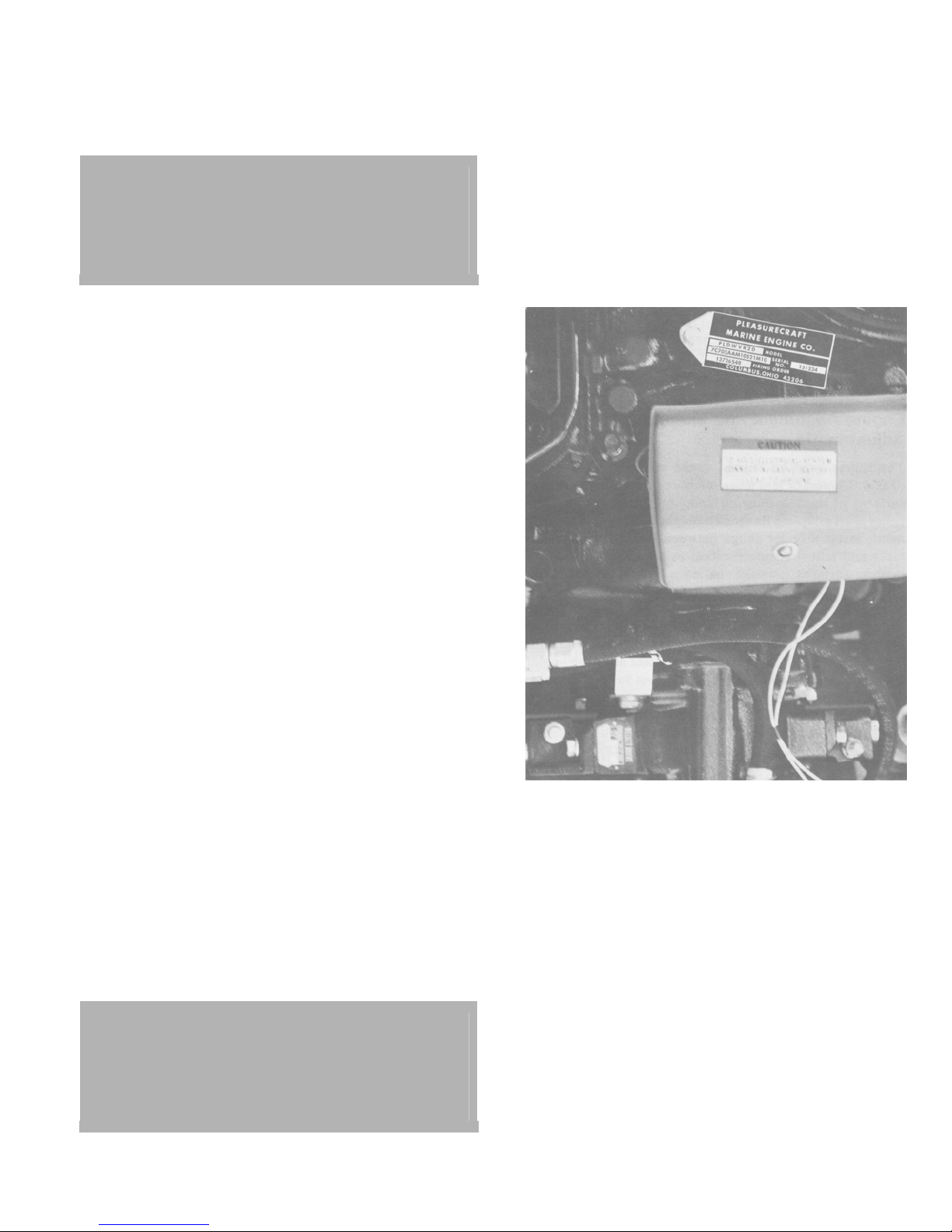
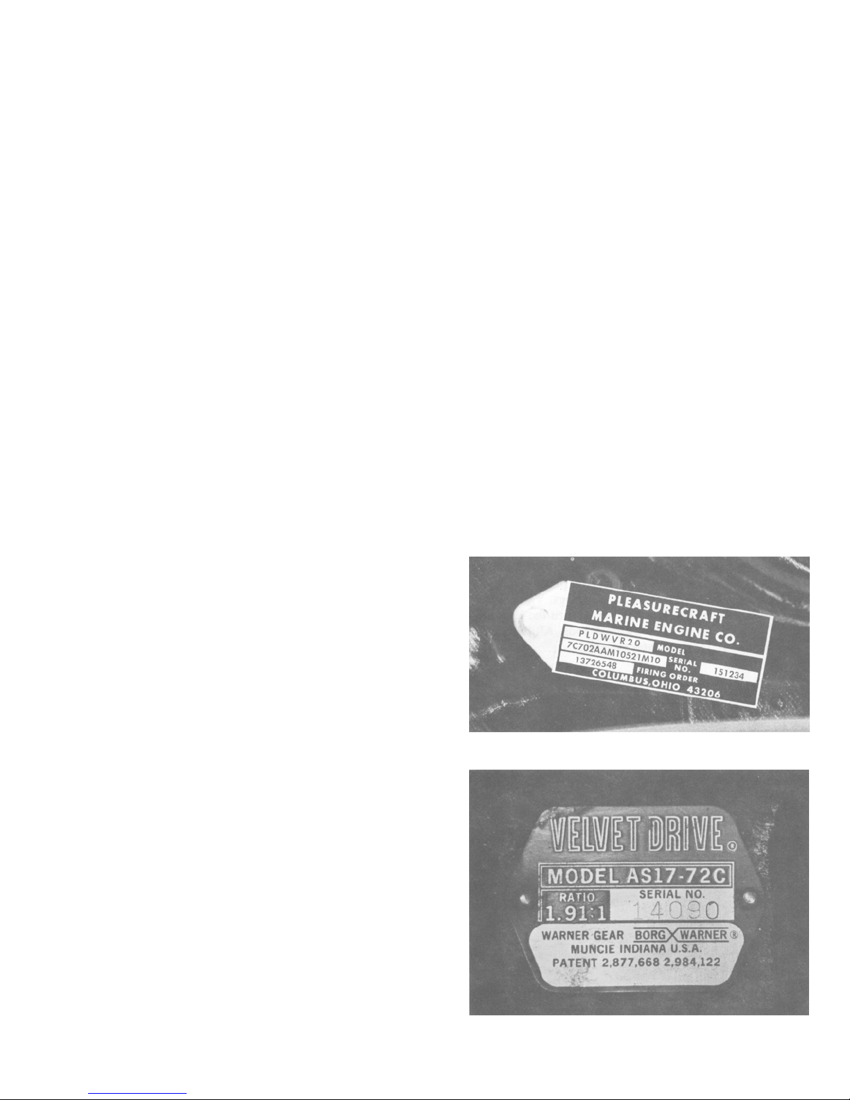
Engine and Transmission Identification
The engine model and serial number are located on the
intake manifold at the rear.
The transmission model, serial number and ratio is located
on the transmission case.
Except for V drives on some applications the propeller shaft
rotation -with the transmission in forward gear on engines
equipped with 1:1, 1.5:1, 2.5:1 and 3:1 transmissions - is the
same as engine rotation.
Propeller shaft rotation - with the transmission in forward
gear on engines equipped with 1.9:1 transmissions - is the
opposite of engine rotation.
On V drive engines both engines may turn the same
direction and have the propeller rotation changed in the V
Drive.
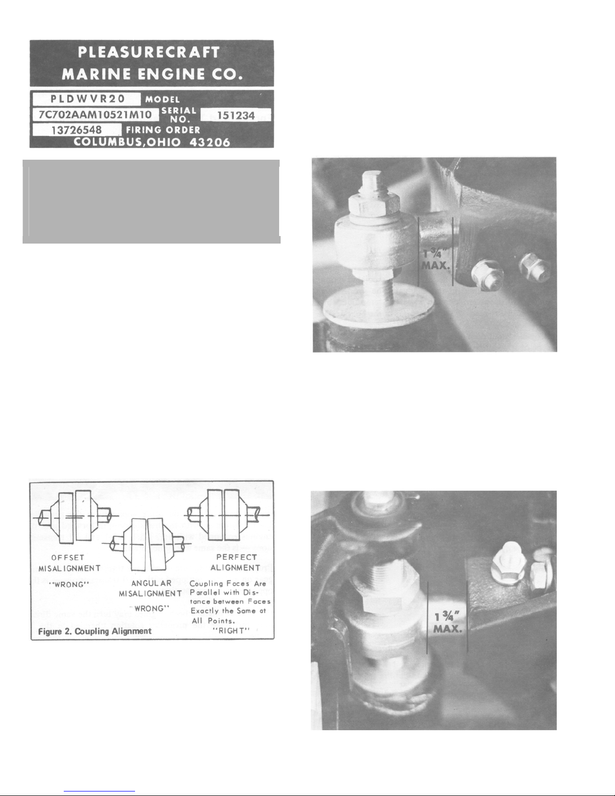
On all engines the Serial # plate indicates both engine and
propeller shaft rotation. Example: PLD-WV-R20 and
PLD-WV-L20. The L following the P indicates the engine
rotation. The R and L following the V and preceding the 20
indicates the Propeller Shaft Rotation. The engines must be
installed accordingly to insure proper propeller rotation.
1
CAUTION: The Warner Gear shift lever MUST BE IN
FORWARD; that is, positioned over the letter "F"
which is embossed in the case casting for
FORWARD gear. Likewise, the shift lever must be
positioned over the letter "R" for REVERSE gear
on all gear models.
Engine Alignment and Mounting Adjustments
The engine must be aligned to the propeller shaft within
.003' (.076mm) or less when measured between the mating
surfaces of the transmission coupling flange and the
propeller shaft coupling flange. To obtain correct engine
alignment, insert a feeler gauge between the coupling mating
faces and adjust engine position as required to place the
mating surfaces parallel to each other within .003' (.076mm).
This clearance must be maintained at all times and at all
positions of the coupling. To complete alignment turn the
shaft coupling 180* from the starting point after the engine
and shaft are aligned to within .003'. Test for proper
clearance. If out readjust the engine to proper clearance.
Retest by turning coupling 90' at a time and testing to insure
alignment at all points through the 360' circle.
Front mounts are adjusted by loosening the upper lock nut
on the mount stud and trunion locking stud nuts and tapping
on the nuts to loosen the studs on the trunion The mount can
then be raised or lowered by screwing the lower nut up or
down in the desired direction and side to side by prying
against the block. CAUTION: Side to side adjustment must
be limited to a maximum 1-3/4: extension of the trunion
from the mount bracket. Extension of more can cause
bending of the trunion or possible mount failure.
Rear mount adjustment is made by loosening the stud lock
nut and turning the stud in the proper direction for vertical
adjustment and by loosening and tapping the nut on the lock
studs to free the rear trunions and adjust in the same manner
as the front for side to side adjustment. CAUTION: Be
certain to lock the lock nuts on the adjusting and lock studs
when adjustment is completed.
After alignment is complete lag and/or cross bolt mounts
securely to the stringers.
The engine mounts are adjustable to permit raising or
lowering the engine and also moving the engine to the right
or left. It is recommended that, when the engine bed is
installed in the boat, it is positioned so that engine alignment
is as close as possible. After engine mounts have been
fastened to the engine bed, final alignment should be done
by adjusting the mounts as follows:
2

Water Pick-Up Installation
Water pickup must be large enough to permit sufficient
water flow to engine seawater pump in order to provide
adequate engine cooling. Pleasurecraft Marine recommends
that a sea strainer be installed on all boats equipped with
transom or thru-hull water pickups to prevent foreign
material from entering and clogging engine cooling systems.
Engine damage that results from a clogged cooling system,
will not be covered by Pleasurecraft's Warranty.
In the interest of safety, it is recommended that a sea cock be
installed between water pickup and sea strainer.
Water pickup should be located as close to seawater pump
inlet as possible and in an area where an uninterrupted, solid
stream of water will flow past it when boat is underway.
Seawater pump inlet is designed for I' I.D. hose. Hose must
have adequate wall thickness to prevent collapsing caused
by pump suction. Hose should be fastened securely at
connections with hose clamps.
EXHAUST SYSTEM
When designing the exhaust system, it is very important that
the following points are taken into consideration:
1. System must not cause an excessive amount of back
pressure. Back pressure must not exceed 4' (10.2cm) of
mercury when measured with a mercury manometer at
the exhaust manifold outlets. Minimum exhaust hose
sizes are as follows:
Dual Exhaust - 3' I.D. (7.6cm)
Single Exhaust - 3-1/2' I.D. (8.9cm)
2. System layout and construction must prevent cooling
system discharge water from flowing back into the
engine and also prevent sea water from entering the
engine via the exhaust system.
Exhaust Hose Installation
The exhaust hose, which connects to the exhaust manifold
riser should be connected so that it does not restrict the flow
of discharge water from the elbow.
Both exhaust manifolds are water-cooled, and all cooling
system water is discharged thru openings which are located
inside the risers. To prevent discharge water from flowing
back into the engine, the exhaust piping must not be higher
than the manifold outlet at any point.
It is the obligation of the boat manufacturer or installing
dealer to correctly locate the engine for installation.
Therefore, if water is present in the exhaust manifolds or
combustion chambers of the engine, the product has not
caused the problem, unless there is a defective part.
Hoses, which are connected in a manner to bend in front of
the exhaust outlet, will prevent discharge water from flowing
around the entire inside diameter of the hose and will cause a
hot spot that may burn through the hose.
The exhaust system should have no sags or low spots to
accumulate water. Sharp bends of more than 45 degrees in
the exhaust lines should be avoided. The exhaust lines
should slope toward the transom at a rate of at least 1/2 in.
per foot with vessel at rest. Exhaust pipe size should not be
restricted. Exhaust back pressure will create poor
performance, high fuel consumption, and severe engine
damage.
Exhaust transom flanges should be above the water line, and
the exhaust lines should be self-draining.
The system should be periodically inspected for leaks and
general condition to prevent leakage of water and exhaust
gases into the hull. Flapper valves are suggested to be used
on all exhaust systems.
Fuel System Installation
Coast Guard Regulations must be observed when installing
fuel system. Fuel systems should be installed in accordance
with the standards of industry associations and applicable
federal standards.
Engine Compartment Air Intake
The engine compartment must be properly vented to provide
a sufficient amount of air for engine breathing. Air intake
and exhaust openings must be large enough to provide an
unrestricted volume of air under all operating conditions.
Engine compartment ventilation also should conform to
Coast Guard Regulations.
Control Cable Adjustments
After installation of controls and cables proceed with the
following adjustments.
Shift Cable
1. Set control lever in neutral position.
2. Position shift selector on the warner gear into neutral
position. In moving the selector from neutral to forward
to reverse to neutral three distinct detent positions will
be felt.
3. Adjust the connector on the control cable so the
connector slips freely into the hole in the selector arm.
4. Remove the connector from the selector arm and move
the selector and control lever into the forward position.
In this position the shift lever must cover the "F" cast
into the transmission case. The connector should slip
freely into the hole in the selector arm.
3

5. Repeat step #4 with the selector and control levers in
reverse position.
If the movement of the connector does not correspond with
the movement of the selector lever it will be necessary to
readjust the remote control head to provide the proper
direction of control cable travel.
CAUTION: Transmissions operated in reverse to
propel the boat forward will fail early. Engine and
propeller rotation must be matched according to
the Serial Plate.
Throttle Cable
1. Place control lever on single lever control into forward
gear without advancing the throttle and on a twin lever
control in the fully closed position.
2. Adjust the connector so that it slips freely into the
connector socket and lock into place.
3. Position throttle into the full throttle position after
blocking the choke open. Check to see if the throttle
valves are in the full open position on both the primary
and secondary side if so equipped.
If valves do not open fully make necessary adjustments
at either control head or cable connector to insure full
opening. Repeat steps #1 and 2 to insure proper idle
settings and adjust if necessary.
Battery Specifications
Battery Specifications Must Be as Follows:
12 volt marine type
Tapered post connectors
70 amp-hr. minimum rating
Battery Cable Size Specifications
Cable Length Cable Size Required
Up to 3 Ft. 6 In. #4 Gauge
3 Ft. 6 In. to 6 Ft. #2 Gauge
6 Ft. to 7 Ft. 6 In. #1 Gauge
7 Ft. 6 In. to 9 Ft. 6 In. #0 Gauge
9 Ft. 6 In. to 12 Ft. #00 Gauge
12 Ft. to 15 Ft. 1 #000 Gauge
15 Ft. to 19 Ft. 2 #0000 Gauge
1 In. (I n c h) = 2.54cm 1 Ft. (Foot) = 30.5cm
NOTE: Cable sizes apply both to positive (+) and
negative (-) cables. Terminals must be
soldered to cable ends to provide adequate
contact.
Battery and Battery Cable Installation
1. Battery should be positioned as close to engine as
possible and should be securely mounted in boat.
2. Connect negative (-) battery cable to ground on engine,
connect positive (+) battery cable to solenoid.
3. Connect positive battery cable to positive post on
battery and negative battery cable to negative (-) post on
battery.
IMPORTANT: Engine electrical system is negative ground.
Failure to connect battery leads, as outlined, will damage
system.
MISCELLANEOUS INSTALLATION INSTRUCTIONS
WARNING: Before starting engine always ventilate
engine compartment by opening engine hatch or, if
equipped, operate bilge blower a sufficient amount
of time to remove any gas fumes from engine
compartment. It is doubly important to check for
fuel spillage or leaks after repair, refueling or
maintenance before starting engine. Remove
battery cable from battery before attempting any
maintenance, repairs or when boat is placed in
storage or in transit.
Check Before Running
1. Engine oil level.
2. Transmission lubricant level.
3. Engine drain plugs installed.
4. Leakage (fuel and water lines and connections).
5. Throttle shutters full close at idle (neutral).
Check While Running (See "Caution", Below)
1. Oil pressure 35 to 40 PSI (2.5 to 2.8kg/cm2) (Approx.)
at 2000 RPM.
2. Water temperature 1401-1600 R/W and 180'-2000 F/W
3. Idle RPM (550-600) in gear
4. Maximum forward RPM 4,400
5. Shifting linkage (forward, neutral and reverse) for shift
lever in detent and proper direction.
6. Leakage (water, oil and fuel)
Check After Initial Run
1. Engine alignment
2. Engine mounting fasteners are tight.
3. Engine oil level
4. Transmission oil level and shift connections.
CAUTION: Do Not Operate Engine without Cooling
Water Flowing thru Water Pump, or Neoprene
Water Pump Impeller Will Become Damaged.
Attach Water Hose to Pump Inlet. Run Engine
Slowly (650-700 RMP) in Neutral to Circulate Water.
Watch Water Temperature Gauge to Prevent
Overheating.
4
Operating Limits (See Specifications for
Your Model)
Maximum RPM at wide open throttle under normal load
conditions can be controlled only by propeller pitch,
diameter, and design. It is essential that the propeller
selected does not overload or underload the engine. Extreme
overloading resulting in low RPM's at wide open throttle
will deliver poor performance, poor fuel economy, and
eventually result in engine damage. Underloading will result
in high RPM, poor fuel economy, and engine damage, if
operated above recommended maximum RPM's.
Do not operate at high RPM's in neutral. Operation in
extremely shallow water can cause sand, silt, and gravel to
be pulled into the cooling system. This can create excessive
water pump wear, and in extreme cases may deposit in the
engine block water jackets and seriously damage the engine
from improper cooling. Heavy weed growth can plug oil
coolers and water intakes and cause damage. If operation
under these conditions is necessary, a good quality sea water
strainer or filter should be installed. The installation of a
fresh water cooling system can reduce the danger of engine
damage from this cause.
ALWAYS OBSERVE HIGH SAFETY STANDARDS
AND COURTESY AFLOAT.
Propellers
Propellers can affect the performance of your boat in many
ways. Selection of the proper propeller for your application
is vital. In most cases, the selection is made by the
Boatbuilder for best over-all performance; however, many
variable factors, such as heavy loads, high altitude, hull
balance, etc., can contribute toward rendering the "standard"
propeller unsuitable, since the application is no longer
"standard."
Many undesirable results can occur from a propeller not
properly matched to the specific application; high RPM's,
low RPM's, cavitation, vibration, steering torque (stem
drives), drumming or rumbling noise, high fuel
consumption, poor efficiency, and even electrolysis damage
(stem drive). When changing propellers, extreme care should
be taken to select a propeller which allows the maximum
engine RPM's with normal load to be within the proper
range for the particular model. See the engine specification
chart in this book for "Maximum RPM."
The use of brass or bronze propellers on stern drives in salt
water or water with high mineral or acid content is not
recommended, due to the possibility of electrolytic attack
and corrosion of the outdrive housings.
If the propeller is bent, broken, out of balance, or otherwise
damaged, limit operation to bare necessity until the propeller
is repaired or replaced.
Directional References
Directional references are given as they appear when
viewing boat from stern, looking toward bow. Front of boat
is bow; rear is stern. Starboard side is right side; port side is
left side.
Service Recommendations
This manual includes operating and maintenance
instructions that are usually required in normal service. Do
not attempt any repairs which are not specifically covered in
this manual. Strict compliance to the recommendations for
lubrication, maintenance, operation, etc., will assure you of
superior performance and dependable service.
Literature
To obtain service and/or parts literature for your PCM
Engine(s) contact your dealer or write:
PCM
P.O. Box 130
Canal Winchester, Ohio 43110
Serial Number Locations
Serial number of your PCM Engine is located at rear of
engine on the Intake Manifold. Transmission serial number
is located on the transmission case.
5

Service Information Request
When contacting the factory, include the following
information:
1. Engine and transmission serial and model numbers.
2. Date purchased.
3. Name of selling dealer.
4. Boat manufacturer, model and length.
5. Number of hours unit has been operated.
6. Date of previous correspondence.
For your convenience there is a form which can be used
when writing PCM.
Record These Numbers from the Serial Number Plates on
the engine and transmission.
Engine Model
Engine Serial No
Transmission Model
Transmission Serial No.
.
Port Starboard
Marine Engine Description
PCM engines are 4-cycle, overhead valve, V-8 engines.
Lubrication is provided by a rotor-type oil pump which
provides full pressure lubrication to all bearings. Valve
rocker arms are lubricated by oil which passes thru the
hydraulic value lifters and up thru hollow push rods. All
lubricating oil is filtered by a full-flow filter system.
PCM Installation and Delivery Inspection
The selling dealer must check the items listed below prior to
delivery of your PCM Engine. Check with him to be sure
that these checks have been completed.
Check and Adjust as Necessary
1. Engine oil level and transmission oil level
2. Battery condition
3. All mounting bolts
4. Engine Alignment
Start Engine and, While Running, Check
CAUTION: DO NOT operate engine without cooling
water flowing through water pump, or water pump
will be damaged, and subsequent engine damage
may result.
(With Engine Warmed-Up at Fast Idle to Normal Operating
Temperature)
1. Oil pressure and cooling water flow
2. Ammeter or voltmeter function
3. Exhaust, oil and fuel system for leaks
4. Idling speed (adjust as necessary)
5. Operation of throttle and shift controls
Test Run Boat and Check (in water)
1. Recommended engine RPM (as stated under
"Specifications")
2. Operation of throttle and shift controls
3. General operation of craft
MAINTENANCE AND
TUNE-UP
Fuel Requirements
Use any good grade automotive regular or premium gasoline
with a minimum average octane rating of 88* (93 research)
in your PCM engine.
An 86* average octane (90 research) gasoline may be used if
the gasoline described above is not available; however, the
ignition timing MUST BE retarded 41 to prevent harmful
detonation.
*New U.S. Regulation requires posting average of
research and motor octane.
PCM reserves the right to refuse warranty on parts which are
damaged -when using improper gasolines.
Replacing Fuel Filter
PCM recommends the use of a Remote Mounted fuel filter
and/or water separator and fuel filter on all its engines. Fuel
filters are not standard with PCM engines, however, we do
offer them as an option to all Boat Builders and Dealers. If
your Boat is not equipped with a fuel filter see your PCM
Dealer. He can provide you with the proper parts and
installation service to protect your engine's fuel system.
When replacing the fuel filter element, follow the
manufacturer's instructions and the following cautions.
CAUTION: Be careful of spilled fuel. Gas vapor
buildup is explosive.
NOTE: DO NOT re-use; always replace with new filter and
gasket.
CAUTION: DO NOT operate engine without cooling
water flowing thru water pump, or water pump
impeller will be damaged, and subsequent engine
damage may result.
6

7
Cleaning Carburetor Inlet Filter
Transmission
Fluid Type
Use only automatic transmission fluid type "A", suffix "A"
in this transmission. This fluid is trade named Dexron.
Change Frequency
Change transmission fluid once each year.
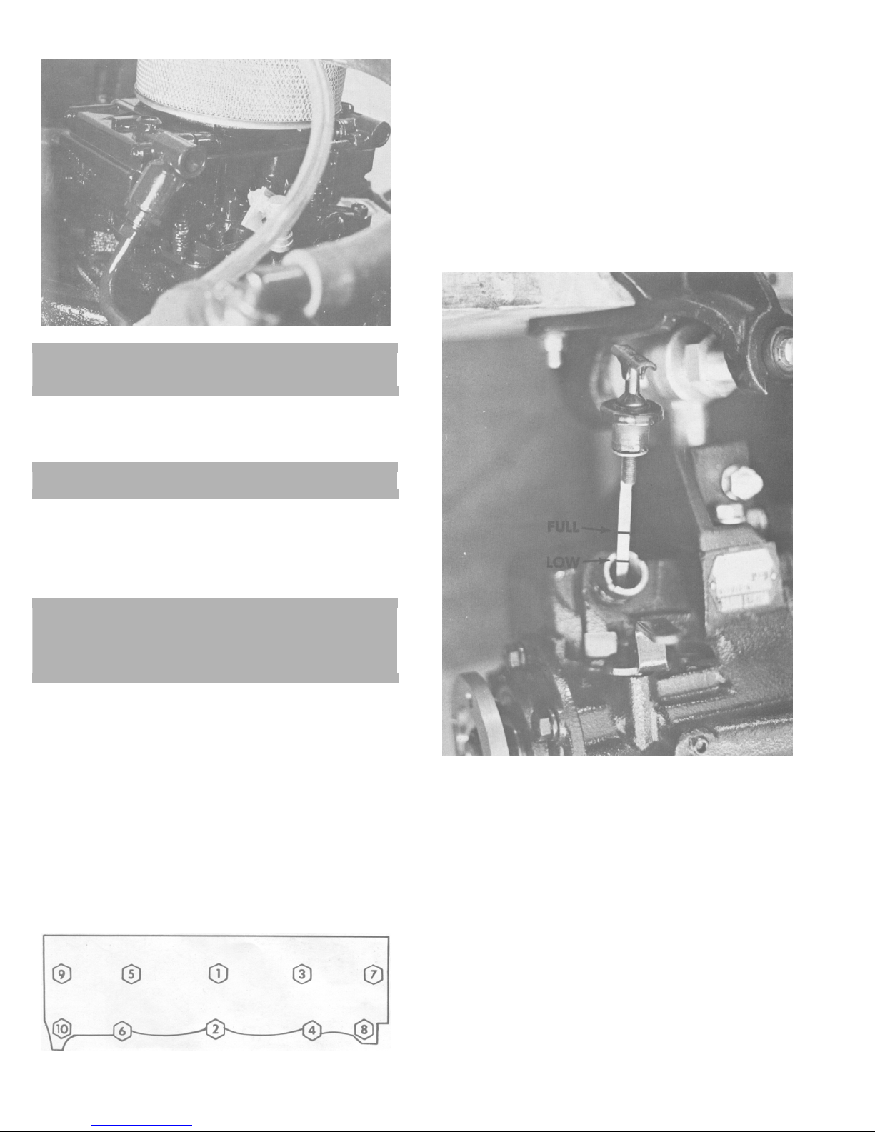
Maintaining Transmission Fluid Level
Transmission fluid level should be checked frequently and
fluid added if necessary. Level must be maintained between
the two marks on dipstick.
CAUTION: Be careful of spilled fuel. Gas vapor
buildup is explosive.
1. Carburetor inlet filter is located in primary float bowl in
fuel inlet fitting.
CAUTION: Use care so fuel is not spilled.
2. Remove fuel line and fuel inlet fitting from carburetor.
3. Wash filter in solvent. Dry with compressed air.
4. Install new gasket on fuel inlet fitting. Install fitting into
carburetor and tighten. Install fuel line.
CAUTION: DO NOT operate engine without cooling
water flowing thru water pump, or water pump
impeller will be damaged, and subsequent engine
damage may result.
5. Run engine and check for gasoline leaks.
Valve Adjustment
Hydraulic valve lifters require little attention. Lifters are
extremely simple in design, readjustments are not necessary
and servicing requires only that care and cleanliness are
exercised in the handling of parts. The best preventive
maintenance for valves is frequent changes of engine oil.
Cylinder Head Torque and Sequence
Cylinder head bolts are tightened in 3 progressive steps.
Torque all bolts in sequence and finally to 100 ft. on 351
engines and 70 ft. lb. on 302 engines.
Maintain fluid level as follows:
1. Boat must be at rest in the water and engine running.
2. Turn dipstick "T" handle counterclockwise and remove
dipstick.
3. Wipe fluid off dipstick and set in position in
transmission fill hole.
4. Remove plug and note level indicated on dipstick. Add
fluid, if required, to bring level up to the top mark.
5. Reinstall dipstick and turn "T" handle clockwise to
tighten.
6. Shut off engine.
Transmission Information Plate
Transmission serial number is located on the transmission
case.
8

SPECIFICATIONS SECTION
Model 351/4 302/2, 302/4
Bore 4.00” 4.00”
Stroke 3.50” 3.00”
Cubic Displacement 351 cubic inches 302 cubic inches
Horsepower 240@4400 RPM 175@4400 302 2/V
220@4400 302 4/V
Intermittent Service 4400 4400
Continuous Cruise 3600 3600
NOTE: Do not cruise at high limits of above range unless propped to turn at or near maximum RPM's at full throttle.
Idle Speed, in forward gear 600 RPM 600 RPM
Timing 10 degrees BTC
@ 600 RPM
Breaker Point Gap .018” .018”
Breaker Point Dwell 24 to 29 degrees 24 to 29 degrees
Spark Plug Gap .035 .035
Spark Plug Type*
*These numbers have been corrected
when copied from original document
Firing Order See engine identification tag* See engine identification tag*
Recommended Fuel Regular grade, leaded
NOTE: Low lead fuel of proper octane rating may be used intermittently. Unleaded fuel should not be used.
Recommended Oil – See Engine Lubrication Section for further information.
Engine 10W30 or 10W40
Warner Drives and
Vee Drives
Carburetor Holley 4 bbl 175 – 2 bbl Holley
Fuel Pump Marine approved,
Electrical System 12 Volt, Negative ground 12 Volt, Negative ground
WARNING: DO NOT reverse battery cables on battery terminals. DO NOT spark battery cables against terminals to
check polarity. Damage to charging system components may result if these precautions are not observed.
Alternator Marine approved, 35 AMP. Marine approved, 35 AMP.
Regulator Sealed solid state
Battery Recommended Marine type of
Oil Capacity 4 quarts and 1 for filter 4 quarts and 1 for filter
* L.H. Rotation
Firing Order
1-3-7-2-6-5-4-8 LC & LD
1-5-4-2-6-3-7-8 LE
Motorcraft BTF3M or
Autolite 124 or
Champion F10. 18MM
Motorcraft ARF32M or
Autolite 24 or
Champion RBL11Y. 14MM
93 octane minimum
(Research method)
premium grade
Automotive Transmission
Fluid (ATF),
Type A, Suffix A. Dexron
double diaphragm,
with safety sight tube
transistorized
70 AMP. hr. minimum
R.H. Rotation
Firing Order
1-8-4-5-6-2-7-3 RC & RD
1-8-7-3-6-2-4-5 RE
10 degrees BTC
@ 600 RPM or lower
Motorcraft BTF3M or
Autolite 124 or
Champion F10. 18MM
Motorcraft ARF32M or
Autolite 24 or
Champion RBL11Y. 14MM
Regular grade, leaded
93 octane minimum
(Research method)
10W30 or 10W40
premium grade
Automotive Transmission
Fluid (ATF),
Type A, Suffix A. Dexron
220 – 4 bbl Holley
Marine approved,
double diaphragm,
with safety sight tube
Sealed solid state
transistorized
Marine type of
70 AMP. hr. minimum
9
 Loading...