


MEFI 4 / 4B
DIAGNOSTIC
MANUAL
5.0/5.7/6.0/8.1L
L510005P
11/05

This page left
intentionally
blank

Marine Electronic Fuel Injection (MEFI 4 / 4B)
Contents
Section 1 - General Information ........................................................................................................................Page 1-1
Section 2 - ECM and Sensors ..........................................................................................................................Page 2-1
Section 3A - Fuel Metering System (5.0/5.7L) ................................................................................................ Page 3A-1
Section 3B - Fuel Metering System (6.0L) .....................................................................................................Page 3B-1
Section 3C - Fuel Metering System (8.1L) .................................................................................................... Page 3C-1
Section 4A - Ignition System (5.0/5.7L) ..........................................................................................................Page 4A-1
Section 4B - Ignition System (6.0/8.1L) ..........................................................................................................Page 4B-1
Section 5 - Diagnosis ........................................................................................................................................Page 5-1
Section 6 - PCV System ...................................................................................................................................Page 6-1
Section 7 - Symptoms .......................................................................................................................................Page 7-1
Section 8 - Master Specifi cations ......................................................................................................................Page 8-1

This page left
intentionally
blank

5.0/5.7/6.0L/8.1L General Information 1 - 1
Marine Electronic Fuel Injection (MEFI)
Section 1
General Information
Contents
General Description .............................................Page 2
Visual/Physical Inspection ...............................Page 2
Basic Knowledge and Tools Required .............Page 2
Electrostatic Discharge Damage ..................... Page 2
Engine Wiring................................................... Page 2
Engine Control Module (ECM)
Self-Diagnostics............................................... Page 2
Malfunction Indicator Lamp (MIL) ................... Page 2
Intermittent Malfunction Indicator Lamp
(MIL) ......................................................... Page 3
Reading Diagnostic Trouble Codes
(DTCs) ......................................................Page 3
Service Mode ............................................Page 3
Normal Mode.............................................Page 3
MEFI On-Board Diagnostic (OBD)
System Check.................................................. Page 3
DLC Scan Tools ............................................... Page 3
Scan Tool Use With Intermittents..................... Page 4
How Diagnostic Trouble Codes Are Set........... Page 4
Clearing Diagnostic Trouble Codes
(Non-Scan) ...................................................... Page 4
Clearing Diagnostic Trouble Codes (Scan) ......Page 5
Non-Scan Diagnosis of Driveability Concerns
(No DTCs Set) .................................................Page 5
Aftermarket (Add-On) Electrical and
Vacuum Equipment...........................................Page 5
Use of Circuit Testing Tools...............................Page 5
Tools Needed to Service the System ...............Page 5
Service Precautions..........................................Page 6
Test Light Amperage Draw Test........................Page 6
Special Tools (1 of 3) .......................................Page 7
Special Tools (2 of 3) .......................................Page 8
Special Tools (3 of 3) .......................................Page 9
Abbreviations.......................................................Page 10
Diagnosis .............................................................Page 11
On-Board Service ................................................Page 11
Wiring Harness Service..................................Page 11
Wiring Connector Service...............................Page 12
Metri-Pack Series 150 Terminals..............Page 12
Weather-Pack Connectors........................Page 13
Micro-Pack 100/W Series Connectors .....Page 14
MEFI 4 - PCM

1 - 2 General Information 5.0/5.7/6.0/8.1L
near a highly charged object and momentarily touches
General Description
Visual and Physical Inspection
Important: This visual and physical inspection is
very important. Perform this inspection carefully and
thoroughly. Perform a careful visual and physical
inspection when performing any diagnostic procedure.
This can often lead to repairing a problem without further
steps. Use the following guidelines when performing a
visual and physical inspection:
• Inspect all vacuum hoses for the following
conditions:
– Correct routing
– Pinches
ground. Charges of the same polarity are drained off,
leaving the person highly charged with the opposite
polarity. Static charges of either type can cause damage.
Therefore, it is important to use care when handling and
testing electronic components.
Engine Wiring
When it is necessary to move any of the wiring, whether
to lift wires away from their harnesses or move harnesses
to reach some component, take care that all wiring is
replaced in its original position and all harnesses are
routed correctly. If clips or retainers break, replace them.
Electrical problems can result from wiring or harnesses
becoming loose and moving from their original positions,
or from being rerouted.
– Cuts
– Disconnects
• Inspect all wires in the engine compartment for the
following conditions:
– Proper connections
– Burned or chafed spots
– Pinched wires
– Contact with sharp edges
– Contact with hot exhaust manifolds
Basic Knowledge and Tools Required
To use this manual most effectively, a general
understanding of basic electrical circuits and circuit
testing tools is required. You should be familiar with wiring
diagrams, the meaning of voltage, ohms, amps and the
basic theories of electricity. You should also understand
what happens if a circuit becomes open, shorted to ground
or shorted to voltage.
To perform system diagnostics, several special tools and
equipment are required. Please become acquainted with
the tools and their use before attempting to diagnose the
system. Special tools that are required for system service
are illustrated in this section.
Electrostatic Discharge Damage
Electronic components used in control systems are often
designed to carry very low voltage, and are very susceptible
to damage caused by electrostatic discharge. It is possible
for less than 100 volts of static electricity to cause damage
to some electronic components. By comparison, it takes
as much as 4,000 volts for a person to feel the zap of
a static discharge.
There are several ways a person can become statically
charged. The most common methods of charging are by
friction and by induction. An e xample of charging b y friction
is a person sliding across a seat, in which a charge of as
much as 25,000 volts can build up. Charging by induction
occurs when a person with well insulated shoes stands
Engine Control Module (ECM) SelfDiagnostics
The Engine Control Module (ECM) performs a continuous
self-diagnosis on certain control functions. This diagnostic
capability is complemented by the diagnostic procedures
contained in this manual. The ECM’s language for
communicating the source of a malfunction is a system of
Diagnostic Trouble Codes (DTC’s). The DTC’s are two digit
numbers that can range from 12 to 81. When a malfunction
is detected by the ECM, a DTC is set and the Malfunction
Indicator Lamp (MIL) is illuminated.
Malfunction Indicator Lamp (MIL)
The Malfunction Indicator Lamp (MIL) is part of the Marine
Diagnostic Trouble Code (MDTC) tool, or it can be a dash
mounted warning light on some boat models.
If present, it informs the operator that a problem has
•
occurred and that the boat should be taken for service
as soon as reasonably possible.
It displays DTC’s stored by the ECM which help the
•
technician diagnose system problems.
As a bulb and system check, the light will come “ON” with
the key “ON,” engine “OFF.” When the engine is star ted,
the light will turn “OFF.” If the light remains “ON,” the
self-diagnostic system has detected a problem. If the
problem goes away, the light may go out, but a DTC will
remain stored in the ECM.
When the light remains “ON” while the engine is running,
or when a malfunction is suspected due to a driveability
problem, the MEFI “On-Board Diagnostic (OBD) System
Check” must be performed as the fi rst step. These checks
will expose malfunctions which may not be detected if other
diagnostics are performed prematurely.
MEFI 4 - PCM
5.0/5.7/6.0L/8.1L General Information 1 - 3
Intermittent Malfunction Indicator Lamp (MIL)
In the case of an “intermittent” problem, the Malfunction
Indicator Lamp (MIL) will light for 10 seconds, and then
go out. However, the corresponding DTC will be stored
in the memory of the ECM. When DTC’s are set by an
intermittent malfunction, they could be helpful in diagnosing
the system.
If an intermittent DTC is cleared, it may or may not reset. If
it is an intermittent failure, consult the “Diagnostic Aids” on
the facing page of the corresponding Diagnostic Procedure.
Symptoms section also covers the topic of “Intermittents.”
A physical inspection of the applicable sub-system most
often will resolve the problem.
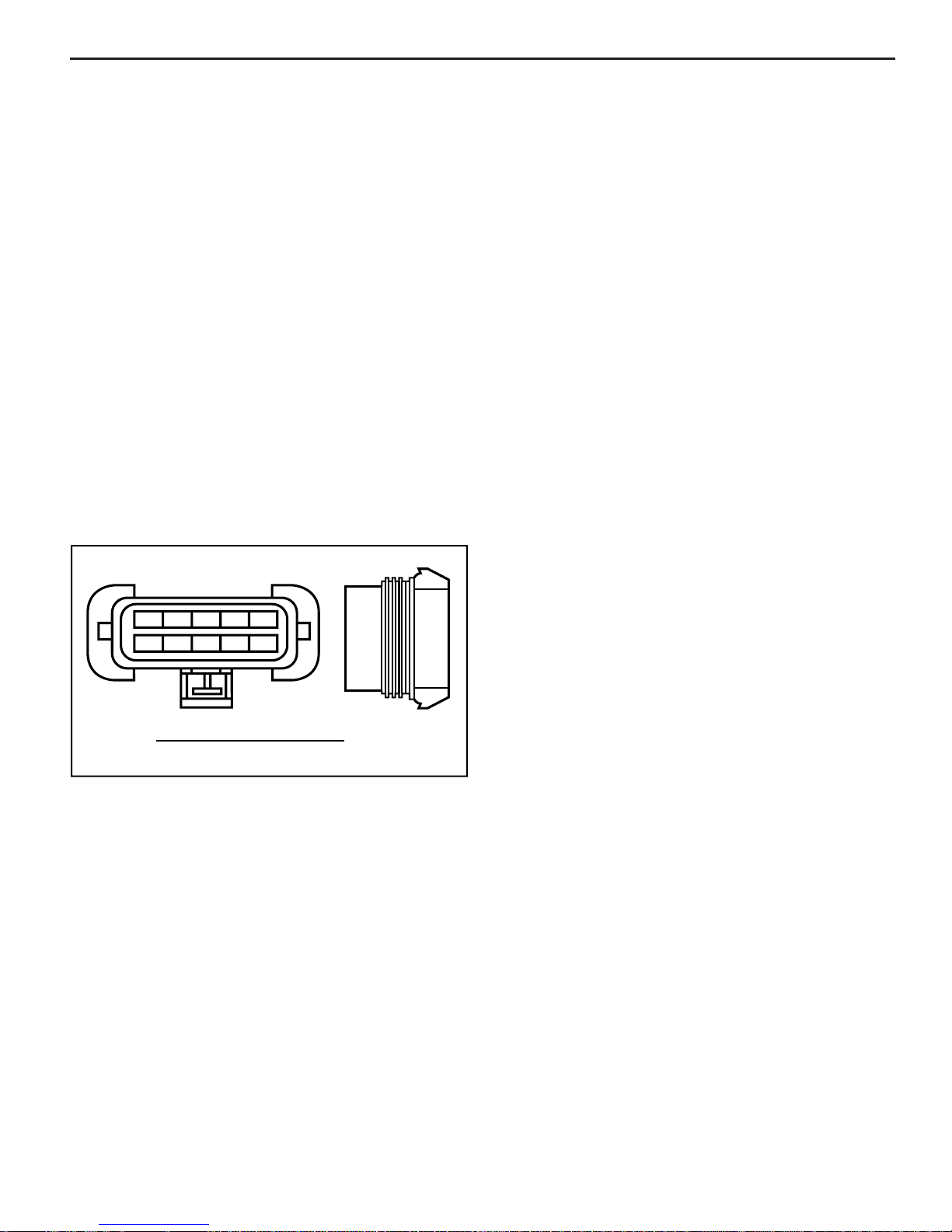
Reading Diagnostic Trouble Codes (DTC’s)
The provision for communicating with the ECM is the Data
Link Connector (DLC) (Figure 1-1). It is part of the MEFI
engine wiring harness, and is a 10-pin connector, which
is electrically connected to the ECM. It is used in the
assembly plant to receive information in checking that the
engine is operating properly before it leaves the plant. The
DTC(s) stored in the ECM’s memory can be retrieved two
different ways. One way is with a Diagnostic Trouble Code
(DTC) tool. The other way is through a scan tool,
A
A B C D E
K J H G F
DATA LINK CONNECTOR (DLC)
B
C
D
E
6-18-93
MS 13554
times. At the end of the DTC’s, the ECM will simply go
back and start over with fl ashing DTC 12.
Service Mode
When the DTC tool is installed at the DLC and “service
mode” or “ON” is selected, the system will enter what is
called the “Service Mode.” In this mode, the ECM will:
• Display a DTC 12 by fl ashing the MIL, indicating that
the diagnostic system is working.
• Display any stored DTC’s by fl ashing the MIL. Each
DTC will be fl ashed two times, then DTC 12 will be
fl ashed again.
Normal Mode
When the DTC tool is in the “normal mode” or “OFF,” it has
no affect on the engine operation.
MEFI On-Board Diagnostic (OBD) System
Check
After the visual/physical inspection, the “On-Board
Diagnostic (OBD) System Check” is the starting point for all
diagnostic procedures. Refer to Diagnosis section.
The correct procedure to diagnose a problem is to follow
two basic steps:
1. Are the on-board diagnostics working? This is
determined by performing the “On-Board Diagnostic
(OBD) System Check.” Since this is the starting point
for the diagnostic procedures, always begin here. If
the on-board diagnostics are not working, the OBD
system check will lead to a Diagnostic Procedure
in the Diagnosis section to correct the problem. If
the on-board diagnostics are working properly, the
next step is:
2. Is there a DTC stored? If a DTC is stored, go directly to
the number DTC procedure in the Diagnosis section.
This will determine if the fault is still present.
Figure 1-1 - Marine Data Link Connector (DLC)
a hand-held diagnostic scanner, plugged into the DLC.
Once the DTC tool has been connected, and “service
mode” or “ON” selected, the ignition switch must be mov ed
to the key “ON,” engine “OFF” position. At this point, the
MIL should fl ash DTC 12 two times consecutively. This
would be the following flash sequence: “flash, pause,
fl ash-fl ash, long pause, fl ash, pause, fl ash-fl ash.” DTC 12
indicates that the ECM’s diagnostic system is operating.
If DTC 12 is not indicated, a problem is present within
the diagnostic system itself, and should be addressed
by consulting the “On-Board Diagnostic (OBD) System
Check” in the Diagnosis section.
Following the output of DTC 12, the MIL will indicate a
DTC two times if a DTC is present, or it will continue to
fl ash DTC 12. If more than one DTC has been stored in
the ECM’s memory, the DTC’s will be fl ashed out from the
lowest to the highest, with each DTC being fl ashed two
DLC Scan Tools
The ECM can communicate a variety of information through
the DLC. This data is transmitted at a high frequency which
requires a scan tool for interpretation.
With an understanding of the data which the scan tool
displays, and knowledge of the circuits involved, the scan
tool can be very useful in obtaining information which
would be more diffi cult or impossible to obtain with other
equipment.
A scan tool does not make the use of Diagnostic Procedures
unnecessary, nor do they indicate exactly where the
problem is in a particular circuit. Some Diagnostic
Procedures incorporate steps with the use of a scan
tool (scan diagnostics), or with the DTC tool (non-scan
diagnostics).
MEFI 4 - PCM

1 - 4 General Information 5.0/5.7/6.0/8.1L
Scan Tool Use With Intermittents
The scan tool provides the ability to perform a “wiggle test”
on wiring harnesses or components with the engine not
running, while observing the scan tool display.
The scan tool can be plugged in and observed while
driving the boat under the condition when the MIL turns
“ON” momentarily, or when the engine driveability is
momentarily poor. If the problem seems to be related to
certain parameters that can be checked on the scan tool,
they should be checked while driving the boat. If there
does not seem to be any correlation between the problem
and any specifi c circuit, the scan tool can be checked on
each position, watching for a period of time to see if there
is any change in the readings that indicates intermittent
operation.
The scan tool is also an easy way to compare the operating
parameters of a poorly operating engine with those of a
known good one. For example, a sensor may shift in value
but not set a DTC.
The scan tool has the ability to save time in diagnosis
and prevent the replacement of good parts. The key to
using the scan tool successfully for diagnosis lies in the
technicians ability to understand the system they are trying
to diagnose, as well as an understanding of the scan tool
operation and limitations. The technician should read the
tool manufacturer’s operating manual to become familiar
with the tool’s operation.
How Diagnostic Trouble Codes (DTC) Are Set
The ECM is programmed to receive calibrated voltage
signals from the sensors. The voltage signal from the
sensor may range from as low as 0.1 volt to as high
as 4.9 volts. The sensor voltage signal is calibrated for
engine application. This would be the sensor’s operating
parameter or “window.” The ECM and sensors will be
discussed further in the ECM and Sensor section.
If a sensor is within its operating or acceptable parameters
(Figure 1-2), the ECM does not detect a problem. When a
sensor voltage signal falls out of this “window,” the ECM
no longer receives a signal voltage within the operating
“window.” When the ECM does not receive the “window”
voltage for a calibratible length of time, a DTC will be
stored. The MIL will be illuminated and a known default
value will replace the sensor value to restore engine
performance.
Clearing Diagnostic Trouble Codes (NonScan)
1. Install Diagnostic Trouble Code (DTC) tool.
2. Ignition “ON,” engine “OFF.”
3. Switch DTC tool to “service mode” or “ON.”
4. Move the throttle from 0% (idle) to 100% (WOT) and
5. Switch DTC tool to “normal mode” or “OFF.” (If this
6. Turn ignition “OFF” for at least 20 seconds.
7. Ignition “ON,” engine “OFF.”
8. Switch DTC tool to “service mode” or “ON” and verify
9. If original DTC(s) are still present, check “Notice” below
10. If new DTC(s) are displayed, perform the OBD system
NOTICE: When clearing DTC’ s with or without the use of a
scan tool, the ignition must be cycled to the “OFF” position
or the DTC’s will not clear.
5 VOLTS
XXXXXXXXXXXXXXX DEFAULTXXXXXXXXXXX
4.6V
V
O
L
T
A
G
E
XXXXXXXXXXXXXXX DEFAULTXXXXXXXXXXX
0 VOLTS
Figure 1-2 - Example of Sensor Normal Operation
TYPICAL SENSOR RANGE
“WINDOW”
0.7V
6-5-93
back to 0%.
step is not performed, the engine may not start and
run).
DTC 12 only. Remove DTC tool.
and repeat the DTC clearing procedure.
check.
MEFI 4 - PCM

5.0/5.7/6.0L/8.1L General Information 1 - 5
Clearing Diagnostic Trouble Codes (Scan)
1. Install scan tool.
2. Start engine.
3. Select “clear DTC’s” function.
4. Clear DTC’s.
5. Turn ignition “OFF” for at least 20 seconds.
6. Turn ignition “ON” and read DTC’s. If DTC’s are still
present, check “Notice” below and repeat procedure
following from step 2.
NOTICE: When clearing DTC’ s with or without the use of a
scan tool, the ignition must be cycled to the “OFF” position
or the DTC’s will not clear.
Non-Scan Diagnosis Of Driveability
Concerns (No DTC’s Set)
If a driveability concern still exists after following the OBD
system check and reviewing the Symptoms section, an
out of range sensor may be suspected. Because of the
unique design of the MEFI system, the ECM will replace
sensed values with calibrated default values in the case of
a sensor or circuit malfunction. By allowing this to occur,
limited engine performance is restored until the boat
is repaired. A basic understanding of sensor operation
is necessary to be able to diagnose an out of range
sensor.
If the sensor is out of range, but still within the operating
“window” of the ECM, the prob lem will go undetected by the
ECM and may result in a driveability concern.
A good example of this would be if the coolant sensor was
reading incorrectly and indicating to the ECM that coolant
temperature was at 50°F, but actual coolant temperature
was at 150°F (Figure 1-3). This would cause the ECM to
deliver more fuel than what was actually needed by the
engine. This resulted in an overly rich condition, causing
rough running. This condition would not have caused
a DTC to set, as the ECM interprets this as within the
operating “window.”
To identify a sensor that is out of range, you may unplug
the sensor electrical connector while the engine is running.
After about 2 minutes, the DTC for that sensor will set,
illuminate the MIL, and replace the sensed value with
a calibrated default value. If at that point, a noticeable
performance increase is observed, the non-scan DTC
table for that particular sensor may be followed to correct
the problem.
NOTICE: Be sure to clear each DTC after disconnecting
and reconnecting each sensor. Failure to do so may result
in a misdiagnosis of the driveability concern.
Aftermarket (Add-On) Electrical And Vacuum
Equipment
Aftermarket, add-on electrical and vacuum equipment is
defi ned as any equipment installed on a vehicle after
leaving the factory that connects to the vehicles electrical
or vacuum systems.
Notice: Do not attach add-on vacuum operated
equipment to this engine. The use of add-on vacuum
equipment may result in damage to engine components
or systems.
Notice: Connect any add-on electrically operated
equipment to the vehicle’s electrical system at the battery
(power and ground) in order to prevent damage to the
vehicle.
Add-on electrical equipment, even when installed to
these strict guidelines, may still cause the powertrain
system to malfunction. This may also include equipment
not connected to the vehicle’s electrical system such as
portable telephones and radios. Therefore, the fi rst step
in diagnosing any powertrain problem, is to eliminate all
aftermarket electrical equipment from the vehicle. After
this is done, if the problem still exists, diagnose the
problem in the normal manner.
Use of Circuit Testing Tools
Do not use a test lamp in order to diagnose the engine
electrical systems unless specifi cally instructed by the
diagnostic procedures. Use the J 35616-A connector
test adapter kit whenever diagnostic procedures call for
probing any connectors.
LOW TEMP - 5 VOLTS
XXXXXXXXXXXXXXX DEFAULTXXXXXXXXXXX
T
------50 -4.2V OUT OF RANGE SENSOR
E
M
P
E
R
A
T
U
R
E
------150 -1.7V ACTUAL COOLANT TEMPERATURE
XXXXXXXXXXXXXXX DEFAULTXXXXXXXXXXX
HIGH TEMP - 0 VOLTS
Figure 1-3 - Example of Shifted Sensor Operation
6-5-93
MS 13552
Tools Needed To Service The System
Refer to Special Tools in this section for engine control
tools for servicing the system.
MEFI 4 - PCM
1 - 6 General Information 5.0/5.7/6.0/8.1L
Service Precautions
The following requirements must be observed when
working on MEFI equipped engines.
1. Before removing any ECM system component,
disconnect the negative battery cable.
2. Nev er start the engine without the battery being solidly
connected.
3. Never separate the battery from the on-board electrical
system while the engine is running.
4. Never separate the battery feed wire from the charging
system while the engine is running.
5. When charging the battery, disconnect it from the
vehicle’s electrical system.
6. Ensure that all cable harnesses are connected solidly
and the battery connections are thoroughly clean.
7. Never connect or disconnect the wiring harness at the
ECM when the ignition is switched “ON.”
8. Before attempting any electric arc welding on the
vehicle, disconnect the battery leads and the ECM
connector(s).
9. When steam cleaning engines, do not direct the nozzle
at any ECM system components. If this happens,
corrosion of the terminals or damage of components
can take place.
10. Use only the test equipment specifi ed in the diagnostic
procedures, since other test equipment may either giv e
incorrect test results or damage good components.
11. All measurements using a multimeter must use a digital
meter with a rating of 10 megaohm input impedance.
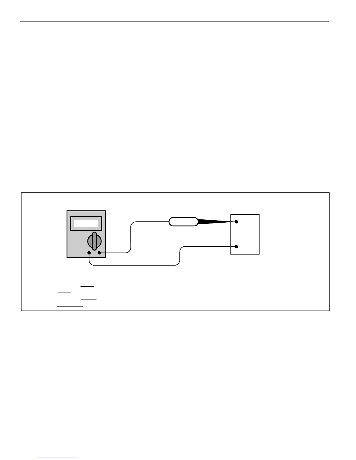
12. When a test light is specifi ed, a “low-power” test light
must be used. Do not use a high-wattage test light.
While a particular brand of test light is not suggested,
a simple test on any test light will ensure it to be safe
for system circuit testing (Figure 1-4). Connect an
accurate ammeter (such as the high-impedance digital
multimeter) in series with the test light being tested,
and power the test light ammeter circuit with the
vehicle battery.
DC Amps
If the ammeter indicates
the testlight is
If the ammeter indicates
the testlight is
safe
to use.
not safe
less
than 3/10 amp(.3A) current flow,
more
than 3/10 amp(.3A) current flow,
to use.
Figure 1-4 - Test Light Amperage Draw Test
testlight
*
+
BATTERY
-
I 22307
MEFI 4 - PCM
5.0/5.7/6.0L/8.1L General Information 1 - 7
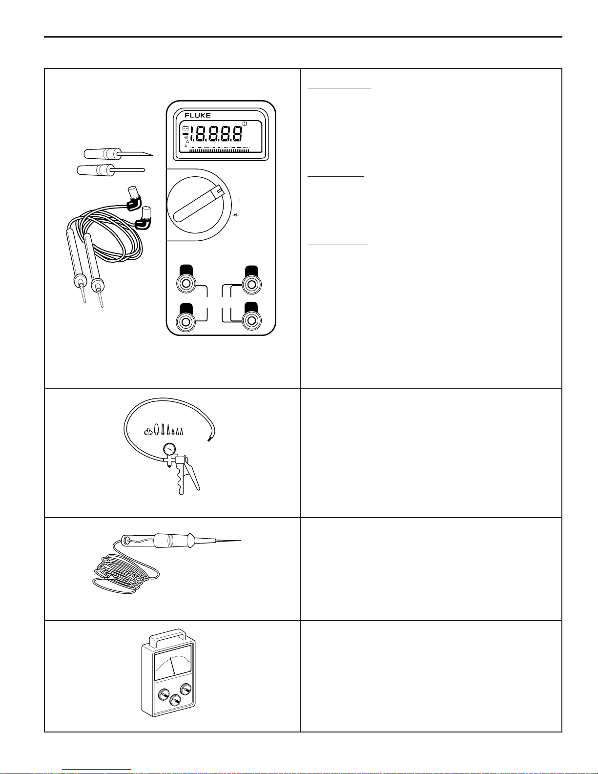
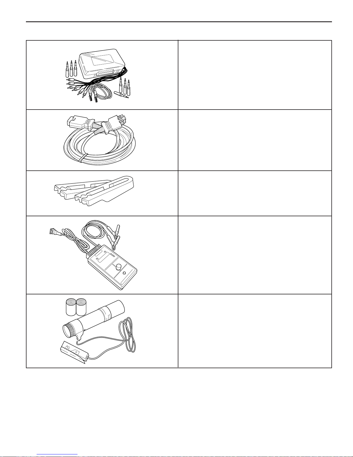
Special Tools (1 of 3)
VOLTMETER - Voltage position measures magnitude of
voltage when connected in parallel to an existing circuit.
A digital voltmeter with a 10 megohm input impedance
is used because this type of meter will not load down
the circuit and result in faulty readings. Some circuits
require accurate low voltage readings because they have
a very high resistance.
AMMETER - When used as an ammeter, this meter
accurately measures extremely low current fl ow. Refer to
meter instructions for more information.
AUTO 100
OFF
0
1234
ms
TRUE RMS MULTIMETER
87
RECORD MAX MIN AVG
5678 90
~
V
_
…
V
…
mV
AC DC
µ
m V A
n F S %
M k Ω Hz
4000
mV
_
(
Ω
• Selector must be set properly for both function and
_
mA
…
~
A
_
…
µ
A
~
range. DC is used for most measurements.
OHMMETER - Measures resistance of circuit directly in
ohms. Refer to meter instructions for more information.
• OL display in all ranges indicates open circuit.
• Zero display in all ranges indicates a short circuit.
400mA MAX
FUSED
10A MAX
FUSED
• An intermittent connection in a circuit may be indicated
by a digital reading that will not stabilize on the
circuit.
• Range Switch - Automatic and Manual.
200ý - Reads ohms directly
2K, 20K, 200Ký - Reads ohms in thousands
J 39978
2M, 20M, 200Mý - Reads ohms in millions
3
➤
2
1
0
TACHOMETER
VACUUM PUMP WITH GAUGE (20 IN. HG. MINIMUM)
Use the gauge to monitor manifold engine vacuum and
use the hand pump to check vacuum sensors, solenoids
and valves.
J 23738-A
UNPOWERED TEST LIGHT
Used for checking wiring for a complete circuit, voltages
and grounds.
J 34142-B
TACHOMETER
4
5
Must have inductive trigger signal pick-up.
NS 14574
MEFI 4 - PCM
1 - 8 General Information 5.0/5.7/6.0/8.1L
Special Tools (2 of 3)
METRI-PACK TERMINAL REMOVER
Used for removing 150 series Metri-Pack “pull-to-seat”
terminals from connectors. Refer to wiring harness
service in MEFI General Information Section for removal
procedure.
J 35689
WEATHER PACK TERMINAL REMOVER
Used for removing terminals from Weather P ack connectors.
Refer to wiring harness service in MEFI General Information
Section for removal procedure.
J 28741-A/BT-8234-A
DIAGNOSTIC TROUBLE CODE (DTC) TOOL
A hand held diagnostic tool that plugs into the DLC
connector for various diagnostics.
TA 06075
RTK0078
J 34730-2C & J 34730-350/BT 8329
RT0086
FUEL PRESSURE GAUGE
Used for checking fuel system pressure on MFI and PFI
engines.
INJECTOR HARNESS TEST LIGHT
A specially designed light used to visually indicate injector
electrical pulses from the ECM.
DIACOM SCAN TOOL
A hand held diagnostic tool that plugs into the DLC
connector for various diagnostics. It will display various
parameters.
MEFI 4 - PCM
5.0/5.7/6.0L/8.1L General Information 1 - 9
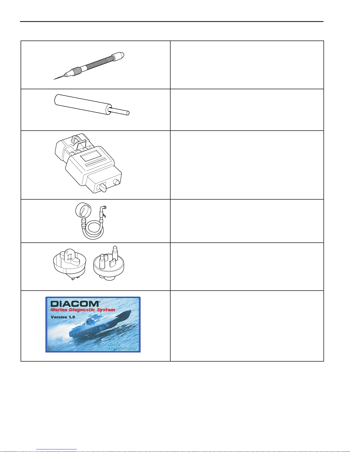
Special Tools (3 of 3)
HARNESS TEST ADAPTER KIT
Used to make electrical test connections in current W eather
Pack, Metri-Pack and Micro-Pack style terminals.
J 35616
20’ DIAGNOSTIC CONNECTOR EXTENSION CABLE
Extension cable to go between the scan tool and the DLC
on the engine harness.
TA 06076
FUEL LINE QUICK-CONNECT SEPARATOR
Used to release fuel line quick-connect fi ttings.
J-39021
J 37088-A/BT-9171
INJECTOR TESTER
Separately energizes each injector to compare for equal
fuel pressure drops over a constant time interval.
+
INJECTOR
VOLTS
-
LOWBATTERY
READYTO TEST
MP
TESTIN PROGRESS
AMP
4AMP
2.5 AMP
PUSHTO TEST
6.5 AMP
KENT-MOORE
J 39021
TIMING LIGHT
Must have inductive signal pickup.
J 34186
MEFI 4 - PCM

1 - 10 General Information 5.0/5.7/6.0/8.1L
ABBREVIATIONS
BARO - BAROMETRIC PRESSURE
BAT - BATTERY, BATTERY POSITIVE
TERMINAL, BATTERY OR SYSTEM
VOLTAGE
B+ - BATTERY POSITIVE
CKP - CRANKSHAFT POSITION SENSOR
CKT - CIRCUIT
CMP - CAMSHAFT POSITION SENSOR
CONN - CONNECTOR
CYL - CYLINDER
DEG - DEGREES
DIAG - DIAGNOSTIC
DLC - DATA LINK CONNECTOR
DMM - DIGITAL MULTIMETER
DTC - DIAGNOSTIC TROUBLE CODE
ECM - ENGINE CONTROL MODULE
ECT - ENGINE COOLANT TEMPERATURE
SENSOR
EEPROM - ELECTRONIC ERASABLE
PROGRAMMABLE READ ONLY
MEMORY
EI - ELECTRONIC IGNITION
EMI - ELECTROMAGNETIC
INTERFERENCE
ENG - ENGINE
GND - GROUND
GPH - GALLONS PER HOUR
HVS - HIGH-VOLTAGE SWITCH
IAC - IDLE AIR CONTROL
IAT - INTAKE AIR TEMPERATURE
IC - IGNITION CONTROL
KS - KNOCK SENSOR SYSTEM
KV - KILOVOLTS
MAP - MANIFOLD ABSOLUTE PRESSURE
MEFI - MARINE ELECTRONIC FUEL
INJECTION
MFI - MULTIPORT FUEL INJECTION
MIL - MALFUNCTION INDICATOR LAMP
MSEC - MILLSECOND
N/C - NORMALLY CLOSED
N/O - NORMALLY OPEN
OBD - ON-BOARD DIAGNOSTIC SYSTEM
CHECK
OPT - OPTIONAL
PFI - PORT FUEL INJECTION
PROM - PROGRAMMABLE READ ONLY
MEMORY
RAM - RANDOM ACESS MEMORY
REF HI - REFERENCE HIGH
REF LO - REFERENCE LOW
ROM - READ ONLY MEMORY
SLV - SLAVE
SW - SWITCH
TACH - TACHOMETER
TBI - THROTTLE BODY INJECTION
TERM - TERMINAL
TP - THROTTLE POSITION SENSOR
V - VOLTS
VAC - VACUUM
WOT - WIDE OPEN THROTTLE
“ HG - INCHES OF MERCURY
IGN - IGNITION
INJ - INJECTOR
I/O - INPUT/OUTPUT
kPa - KILOPASCAL
MEFI 4 - PCM

5.0/5.7/6.0L/8.1L General Information 1 - 11
T endency f or connectors to come apart due to vibration
Diagnosis
The diagnostic tables and functional checks in this manual
are designed to locate a faulty circuit or component through
logic based on the process of elimination. The tables are
prepared with the requirement that the system functioned
correctly at the time of assembly and that there are no
multiple failures.
Engine control circuits contain many special design features
not found in standard vehicle wiring. Environmental
protection is used extensively to protect electrical contacts.
Proper splicing methods must be used when necessary.
The proper operation of low amperage input/output circuits
depend upon good continuity between circuit connectors. It
is important before component replacement and/or during
normal troubleshooting procedures that a visual inspection
of any questionable mating connector is performed. Mating
surfaces should be properly formed, clean and likely to
make proper contact. Some typical causes of connector
problems are listed below:
Improperly formed contacts and/or connector
•
housing.
Damaged contacts or housing due to improper
•
engagement.
Corrosion, sealer or other contaminants on the contact
•
mating surfaces.
Incomplete mating of the connector halves during
•
initial assembly or during subsequent troubleshooting
procedures.
•
and/or temperature cycling.
Terminals not fully seated in the connector body.
•
Inadequate terminal crimps to the wire.
•
On-Board Service
Wiring Harness Service
Figure 1-5
Wiring harnesses should be replaced with proper part
number harnesses. When wires are spliced into a harness,
use the same gauge wire with high temperature insulation
only.
With the low current and voltage levels found in the
system, it is important that the best possible bond be
made at all wire splices by soldering the splices as shown
in Figure 1-5.
Use care when probing a connector or replacing a connector
terminal. It is possible to short between opposite terminals.
If this happens, certain components can be damaged.
Always use jumper wires with the corresponding mating
terminals between connectors for circuit checking. NEVER
probe through connector seals, wire insulation, secondary
ignition wires, boots, nipples or covers. Microscopic
damage or holes may result in water intrusion, corrosion
and/or component failure.
DRAIN WIRE
OUTER JACKET
MYLAR
1REMOVE OUTER JACKET.
2UNWRAP ALUMINUM/MYLAR TAPE. DO NOT
REMOVE MYLAR.
3UNTWIST CONDUCTORS. STRIP INSULATION AS
NECESSARY.
DRAIN WIRE
4SPLICE WIRES USING SPLICE CLIPS AND ROSIN CORE
SOLDER. WRAP EACH SPLICE TO INSULATE.
5WRAP WITH MYLAR AND DRAIN (UNINSULATED) WIRE.
6TAPE OVER WHOLE BUNDLE TO SECURE AS BEFORE.
1LOCATE DAMAGED WIRE.
2REMOVE INSULATION AS REQUIRED.
3SPLICE TWO WIRES TOGETHER USING SPLICE
CLIPS AND ROSIN CORE SOLDER.
4COVER SPLICE WITH TAPE T O INSULA TE
FROM OTHER WIRES.
5RETWIST AS BEFORE AND TAPE WITH
ELECTRICAL TAPE AND HOLD IN PLACE.
8-24-94
RS 22186
Figure 1-5 - Wiring Harness Repair
MEFI 4 - PCM
1 - 12 General Information 5.0/5.7/6.0/8.1L
Wiring Connector Service
Most connectors in the engine compartment are protected
against moisture and dirt which could create oxidation
and deposits on the terminals. This protection is important
because of the very low voltage and current levels found
in the electronic system. The connectors have a lock
which secures the male and female terminals together.
A secondary lock holds the seal and terminal into the
connector.
When diagnosing, open circuits are often diffi cult to locate
by sight because oxidation or terminal misalignment are
hidden by the connectors. Merely wiggling a connector on
a sensor, or in the wiring harness, may locate the open
circuit condition. This should always be considered when
an open circuit or failed sensors is indicated. Intermittent
problems may also be caused by oxidized or loose
connections.
Before making a connector repair, be certain of the type of
connector. Some connectors look similar but are serviced
differently.
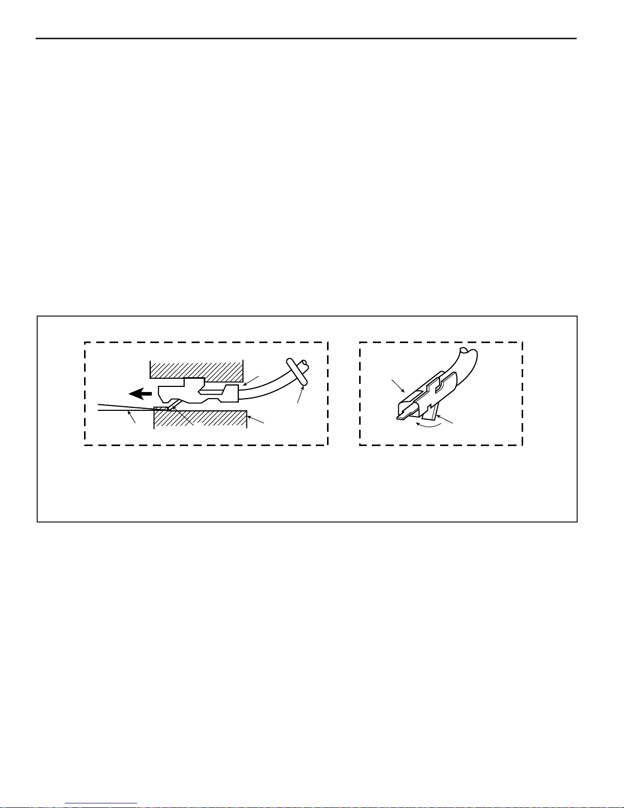
Metri-Pack Series 150 Terminals
Figure 1-6
Some ECM harness connectors contain terminals called
Metri-Pack (Figure 1-6). These are used at some of the
sensors and the distributor connector.
Metri-Pack terminals are also called “Pull-To-Seat”
terminals because, to install a terminal on a wire, the wire is
fi rst inserted through the seal and connector. The terminal
is then crimped on the wire, and the terminal is pulled back
into the connector to seat it in place.
To remove a terminal:
1. Slide the seal back on the wire.
2. Insert tool J 35689 or equivalent, as shown in Figure
1-6, to release the terminal locking tang.
3. Push the wire and terminal out through the connector.
If the terminal is being reused, reshape the locking
tang.
AB
1
5
3
1. METRI-PACK SERIES
150 FEMALE TERMINAL.
2. LOCKING T ANG.
RS 22187
2
Figure 1-6 - Metri-Pack Series 150 Terminal Removal
4
3. TOOL J35689 OR BT-8446.
4. CONNECTOR BODY.
5. SEAL.
1
2
MEFI 4 - PCM
5.0/5.7/6.0L/8.1L General Information 1 - 13
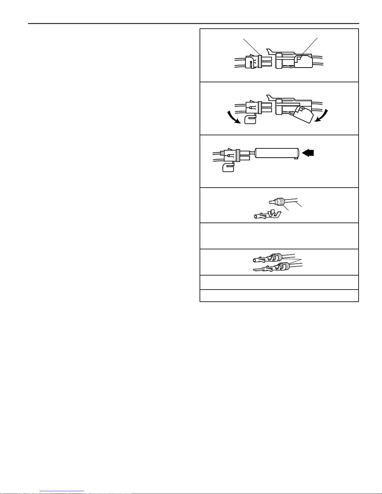
Weather-Pack Connectors
Figure 1-7
Figure 1-7 shows a Weather-Pack connector and the
tool (J 28742 or equivalent) required to service it. This
tool is used to remove the pin and sleeve terminals. If
terminal removal is attempted without using the special
tool required, there is a good chance that the terminal
will be bent or deformed, and unlike standard blade type
terminals, these terminals cannot be straightened once
they are bent.
Make certain that the connectors are properly seated and
all of the sealing rings in place when connecting leads.
The hinge-type fl ap provides a secondary locking feature
for the connector. It improves the connector reliability by
retaining the terminals if the small terminal lock tangs are
not positioned properly. Weather-Pack connections cannot
be replaced with standard connections.
MALE
CONNECTOR
BODY
1. OPEN SECONDARY LOCK HINGE ON CONNECTOR
2. REMOVE TERMINAL USING TOOL
TERMINAL REMOVAL TOOL
J 28742, J 38125-10 OR BT-8234-A
3. CUT WIRE IMMEDIATELY BEHIND CABLE SEAL
SEAL
FEMALE
CONNECTOR
BODY
PUSH TO
RELEASE
WIRE
4. REPLACE TERMINAL
A. SLIP NEW SEAL ONTO WIRE
B. STRIP 5mm (.2") OF INSULATION FROM WIRE
C. CRIMP TERMINAL OVER WIRE AND SEAL
SEAL
5. PUSH TERMINAL INTO CONNECTOR
UNTIL LOCKING TANGS ENGAGE
6. CLOSE SECONDARY LOCK HINGE
RS 22188
Figure 1-7 - Weather-Pack Terminal Repair
MEFI 4 - PCM

1 - 14 General Information 5.0/5.7/6.0/8.1L
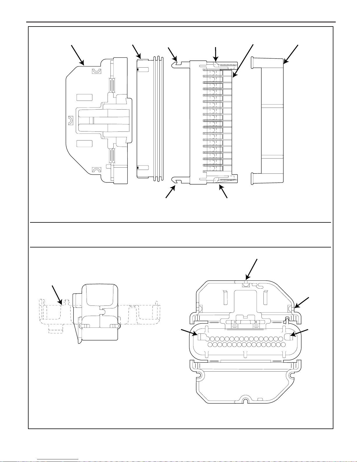
Micro-Pack 100/W Series Connectors
Figure 1-8
The harness connectors used with the ECM “J1” and “J2”
connectors are Micro-Pack 100/W Series. It is used for its
ruggedized construction, capable of carrying more current
and provides good sealing ability. The connector is made
up of fi ve different parts (refer to Figure 1-8 View A): Str ain
Relief (1), Seal (2), Connector (3), Index Cover (4) and
Ter minals (not shown).
Remove or Disconnect
1. Negative battery cable.
2. Connector from ECM by lifting up locking tab with
thumb and pulling on connector body.
Inspect
Check strain relief for being cracked or locking tab
•
damaged.
Check index cover for being cracked.
•
Check seal for being torn, twisted or out of shape from
•
improper installation.
Check terminals for being corroded, out of position,
•
bent or stretched out.
Use a wire gauge .038 for checking terminal
–
internal fi t. Wire gauge should slide with smooth
feel and not be loose.
Notice: If you are only going to clean terminals, complete
disassembly is not necessary. Remove index cover from
the connector by pushing on Tab C on both sides and
sliding off cover. Care m ust be tak en not to mov e terminals
out of their position. The index cover locks the terminals
in position. If repair or replacement of parts is needed, DO
NOT remove index cover at this time.
3. With a small screwdriver, move Tabs A on strain relief
(1) to unlock position.
4. Open strain relief as shown in View B.
5. Release Tabs B (View C) on connector (3) by pushing
inward with both thumbs or small screwdriver.
6. Push Tabs B through strain relief (1) with thumbs or
small screwdriver while in released position.
Important
Where there are not wires in strain relief, small plugs
•
are installed. DO NO T lose the plugs, they are important
to help keep connector assembly sealed.
7. Remove plugs where there are not any wires.
8. Slide strain relief off of seal and back on wires.
9. Slide seal off of connector and back on wires.
Important
To ensure proper engine operation after repair of
•
connector assembly , wires must be in proper connector
location. Before removing index cover, note if there
are any wires of the same color. Mark these wires from
the location that they were remov ed. For the remaining
wires, their location can be found by ref erring to “Wiring
Diagrams” in the Diagnosis section. The strain relief is
numbered for identifying wire location.
10. Index cover (4) by pushing in on Tabs C with a small
screwdriver.
11. Ter minals by pulling out of connector.
12. Seal (2) from wires.
13. Strain relief (1) from wires.
Clean and Inspect
Terminals for corrosion.
•
– Use spray electrical contact cleaner.
Loose crimps on terminals.
•
Broken wires at terminals.
•
Notice: For terminal replacement, refer to instructions
found with terminal repair kit and crimper tool.
Install or Connect
1. Align index cover (4) on connector (3) and lock into
position. Make sure Tabs C are locked.
2. Align seal (2) on connector (3) and slide all the way
on.
DO NOT install strain relief (1) onto connector (3)
•
yet.
3. One wire with terminal installed, through strain relief
(1) in location that it was removed.
Start with the lowest numbered wire position for
•
that connector.
4. Terminal through seal (2), connector (3) and into inde x
cover (4) until it locks in place.
5. Remaining wires one at a time per same method.
• Keep wires straight.
DO NOT kink wires.
•
6. Strain relief (1) onto seal (2) and connector (3).
7. Lock Tabs B into strain relief (1).
8. Plugs into strain relief (1) where there are not any
wires.
9. Fold strain relief (1) together and lock Tabs A.
10. Connector assembly to ECM.
11. Negative battery cable.
MEFI 4 - PCM
5.0/5.7/6.0L/8.1L General Information 1 - 15
1
2
TAB B
TAB B
TAB C
TAB C
34
FIGURE A - EXPLODED VIEW OF CONNECTOR ASSEMBLY
1 STRAIN RELIEF
2 SEAL
TAB A
FIGURE B - STRAIN RELIEF CLOSED
TAB B
3 CONNECTOR
4 INDEX COVER
TAB A
21 3 4 5 6 7 8 9 10111213141516
1817 1920212223242526272829303132
TAB A
TAB B
FIGURE C - STRAIN RELIEF OPENED
PS 19745
Figure 1-8 - Micro-Pack 100/W Series
MEFI 4 - PCM

1 - 16 General Information 5.0/5.7/6.0/8.1L
This page left
intentionally
blank
MEFI 4 - PCM

5.0/5.7/6.0L/8.1L ECM and Sensors 2 - 1
Marine Electronic Fuel Injection (MEFI)
Section 2
Engine Control Module (ECM) and Sensors
This section will describe the function of the Engine Control Module (ECM) and the sensors. The section explains
how voltages reflect the inputs and outputs of the ECM. The sensors are described how they operate and how
to replace them.
Contents
General Description .............................................Page 2
Computers and Voltage Signals.......................Page 2
Analog Signals.................................................Page 2
Three-Wire Sensors ..................................Page 2
Two-Wire Sensors .....................................Page 2
Digital Signals..................................................Page 3
Switch Types..............................................Page 3
Pulse Counters..........................................Page 3
Engine Control Module (ECM).........................Page 4
ECM Function............................................Page 4
Memory .....................................................Page 4
ROM..........................................................Page 4
RAM...........................................................Page 4
EEPROM...................................................Page 4
Speed Density System ....................................Page 5
Speed........................................................Page 5
Density.......................................................Page 5
ECM Inputs and Sensor Descriptions..............Page 5
Input Components............................................Page 5
Output Components.........................................Page 5
MEFI Inputs and Outputs ..........................Page 6
Engine Coolant Temperature (ECT)
Sensor.......................................................Page 7
Manifold Absolute Pressure (MAP)
Sensor.......................................................Page 7
Throttle Position (TP) Sensor....................Page 8
Intake Air Temperature (IAT) Sensor.........Page 8
Ignition Control (IC) Reference..................Page 8
Knock Sensor............................................Page 9
Discrete Switch Inputs...............................Page 9
Diagnosis ............................................................Page 10
Engine Control Module (ECM).......................Page 10
On-Board Service ...............................................Page 10
Engine Control Module (ECM)
Replacement..................................................Page 10
System Relay.................................................Page 11
Fuel Pump Relay ...........................................Page 11
Starter Relay..................................................Page 11
Engine Coolant Temperature (ECT)
Sensor............................................................Page 12
Manifold Absolute Pressure (MAP)/Intake Air
Temperature (IAT) Sensor (5.0/5.7L).............Page 13
Manifold Absolute Pressure (MAP)
Sensor (6.0/8.1L)...........................................Page 14
Throttle Position (TP) Sensor.........................Page 16
Idle Air Control (IAC) Valve............................Page 17
Knock Sensor (KS) (5.0/5.7L)........................Page 18
Knock Sensors (KS) (6.0L)............................Page 18
Torque Specifi cations ........................................Page 20
MEFI 4 - PCM
2 - 2 ECM and Sensors 5.0/5.7/6.0/8.1L
General Description
The Marine Electronic Fuel Injection (MEFI) system is
equipped with a computer that provides the operator with
state-of-the-art control of fuel and spark delivery. Before
we discuss the computers on the Marine applications,
let’s discuss how computers use voltage to send and
receive information.
Computers and Voltage Signals
Voltage is electrical pressure. Voltage does not flow
through circuits. Instead, voltage causes current. Current
does the real work in electrical circuits. It is current, the fl ow
of electrically charged particles, that energizes solenoids,
closes relays and illuminates lamps.
Besides causing current fl ow in circuits, voltage can be
used as a signal. Voltage signals can send information by
changing levels, changing waveform (shape) or changing
the speed (frequency( at which the signal switches from
one level to another. Computers use voltage signals to
communicate with one another. The different circuits
inside computers also use voltage signals to talk to each
other.
There are two kinds of voltage signals, analog and digital.
Both of these are used in computer systems. It is important
to understand the difference between them and the different
ways they are used.
Analog Signals
An analog signal is continuously variable. This means that
the signal can be any voltage within a certain range.
An analog signal usually gives information about a condition
that changes continuously over a certain range. For
example, in a marine engine, temperature is usually
provided by an analog signal. There are two general types
of sensors that produce analog signals, the 3-wire and
the 2-wire sensors.
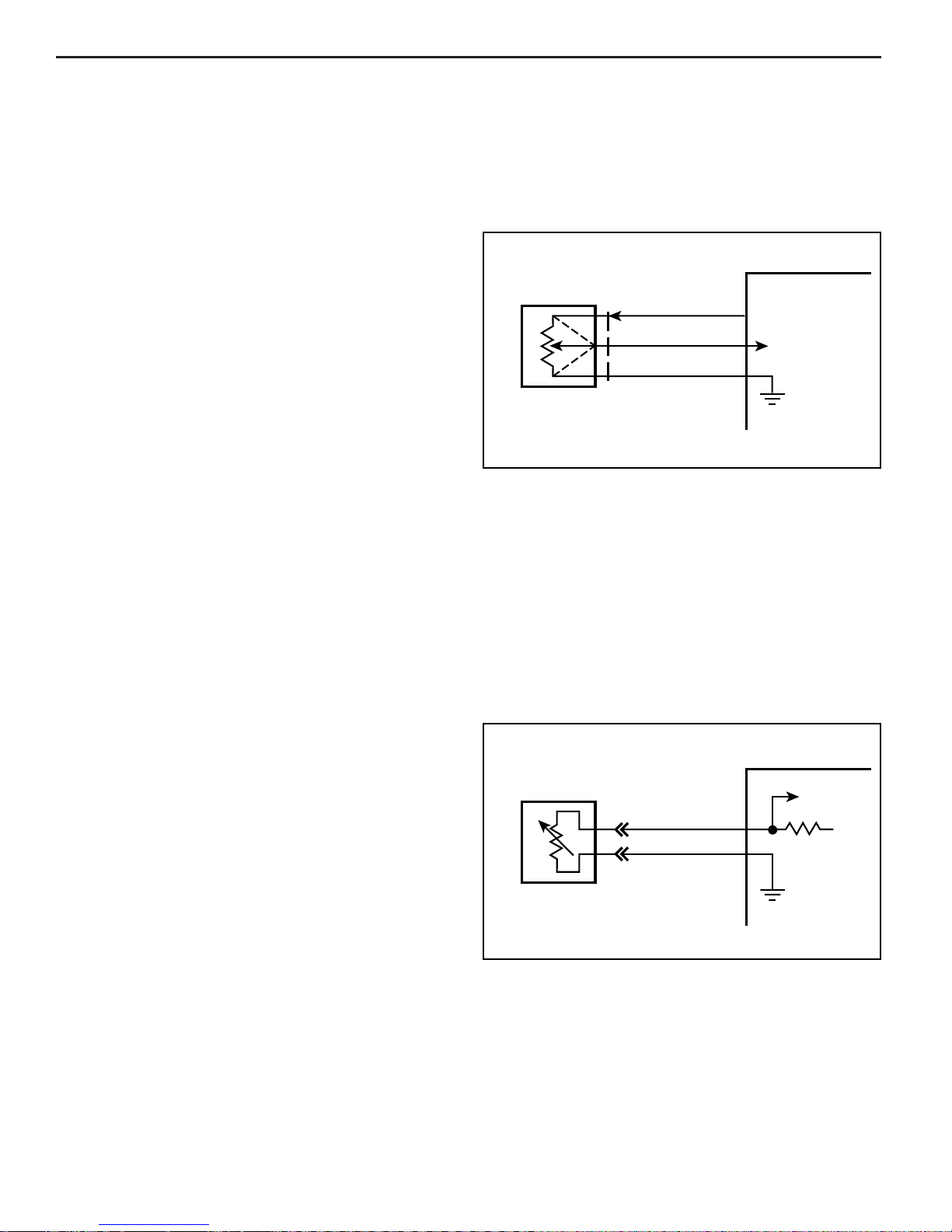
Three-Wire Sensors
Figure 2-1 shows a schematic representation of a 3-wire
sensor. All 3-wire sensors have a reference voltage, a
ground and a variable “wiper.” The lead coming off of the
“wiper” will be the signal to the Engine Control Module
(ECM). As this “wiper” position changes, the signal voltage
to the ECM also changes.
ECM
TYPICAL
SENSOR
Figure 2-1 - Three-Wire Sensors
VOLTAGE OUT
SIGNAL INPUT
4-24-91
MS 11697
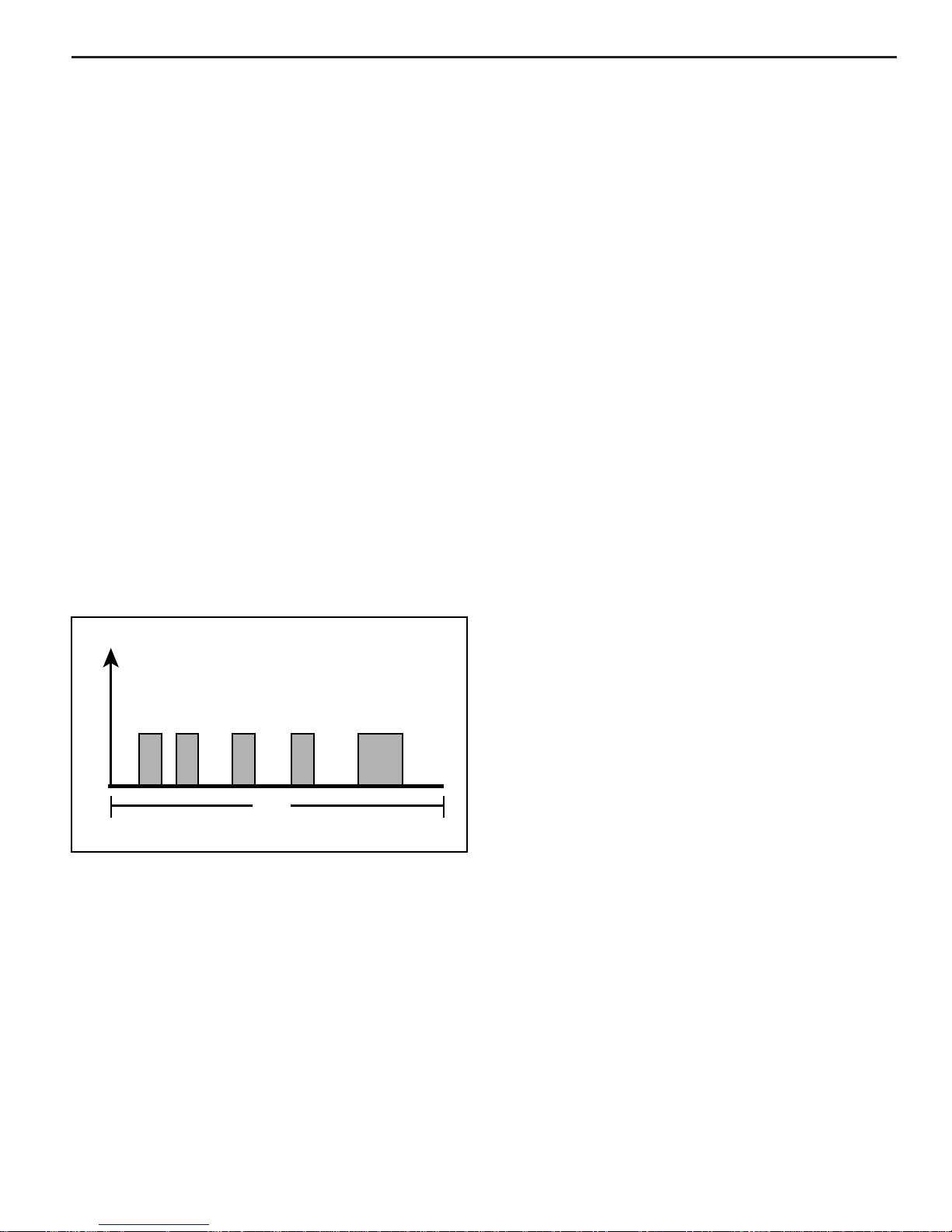
Two-Wire Sensors
Figure 2-2 shows a schematic representation of a 2-wire
sensor. This sensor is basically a variable resistor in series
with a known-fi xed resistor within the ECM. By knowing
the values of the input voltage and the v oltage drop across
the known resistor, the value of the variable resistor can
be determined. The variable resistors that are commonly
used are called thermistors. A thermistor’s resistance
varies with temperature.
ECM
TYPICAL
SENSOR
SENSOR
SIGNAL
5V
MEFI 4 - PCM
SENSOR
GROUND
4-24-91
MS 11698
Figure 2-2 - Two-Wire Sensors
5.0/5.7/6.0L/8.1L ECM and Sensors 2 - 3
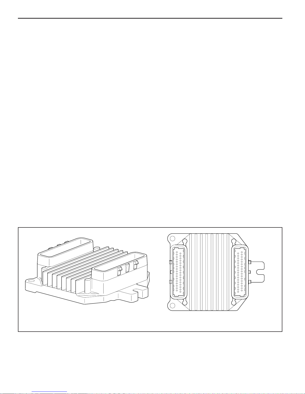
Digital Signals
Digital signals are also variable, but not continuously. They
can only be represented by distinct voltages within a range .
For example, 1V, 2V or 3V would be allowed, but 1.27V or
2.56V would not. Digital signals are especially useful when
the information can only refer to two conditions: “YES” and
“NO,” “ON” and “OFF” or “HIGH” and “LOW.” This would
be called a digital binary signal. A digital binary signal is
limited to two voltage lev els . One lev el is a positiv e voltage ,
the other is no voltage (zero volts). As y ou can see in Figure
2-3, a digital binary signal is a square wave.
The ECM uses digital signals in a code that contains only
ones and zeros. The high voltage of the digital signal
represents a one (1), and no voltage represents a zero (0).
Each “zero” and each “one” is called a bit of information,
or just a “bit.” Eight bits together are called a “word.”
A word, therefore, contains some combination of eight
binary code bits.
Binary code is used inside the ECM and between a
computer and any electronic device that understands the
code. By stringing together thousands of bits, computers can
communicate and store an infi nite varieties of information.
To a computer that understands binar y, 11001011 might
mean that it should turn an output device “ON” at slow
speed. Although the ECM uses 8-bit digital codes internally
and when talking to another computer, each bit can have
a meaning.
Switch T ypes
Switched inputs (also known as discretes) to the ECM can
cause one bit to change, resulting in information being
communicated to the ECM. Switched inputs can come
in two types: “pull-up” and “pull-down” types. Both types
will be discussed.
With “pull-up” type switch, the ECM will sense a voltage
when the switch is CLOSED. With “pull-down” type switch,
the ECM will sense a voltage when the switch is OPEN.
Pulse Counters
For the ECM to determine frequency information from a
switched input, the ECM must measure the time between
the voltage pulses. As a number of pulses are recorded in
a set amount of time, the ECM can calculate the frequency.
The meaning of the frequency number can have any
number of meanings to the ECM.
An example of a pulse counter type of input is the
Crankshaft Position (CKP) sensor input. The ECM can
count a train of pulses, a given number of pulses per
engine revolution. In this way, the ECM can determine
the RPM of the engine.
V
O
L
T
A
G
E
DIGITAL BINARY SIGNAL
TIME
4-18-91
MS 11696
Figure 2-3 - Digital Voltage Signal
MEFI 4 - PCM
2 - 4 ECM and Sensors 5.0/5.7/6.0/8.1L
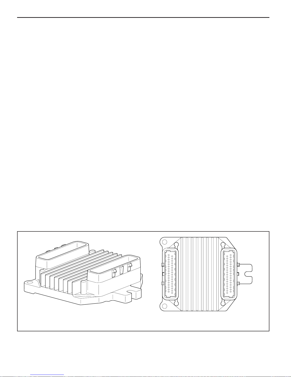
Engine Control Module (ECM)
The Engine Control Module (ECM), located on the engine,
is the control center of the fuel injection system. It controls
the following:
• Fuel control circuit
• Ignition control circuit
• Idle Air Control (IAC)
• Knock Sensor (KS) system
• On-board diagnostics for engine functions
It constantly looks at the information from various sensors,
and controls the systems that affect engine performance.
The ECM also performs the diagnostic function of the
system. It can recognize operational problems, alert the
operator through the MIL (Malfunction Indicator Lamp)
and store diagnostic trouble codes, or logged warnings,
which identify the problem areas to aid the technician
in making repairs. Refer to General Information section
for more information on using the diagnostic function
of the ECM.
ECM Function
The ECM supplies either 5 or 12 volts to power various
sensors or switches. This is done through resistances in
the ECM which are so high in value that a test light will
not light when connected to the circuit. In some cases,
even an ordinary shop voltmeter will not give an accurate
reading because its resistance is too low. Therefore, a
digital voltmeter with at least 10 megohms input impedance
is required to ensure accurate voltage readings. Tool J
39978 meets this requirement.
The ECM controls output circuits such as the injectors,
IAC, relays, etc. by controlling the ground or power feed
circuit.
Memory
There are three types of memory storage within the ECM.
They are ROM, RAM and EEPROM.
ROM
Read Only Memory (ROM) is a permanent memory that is
physically soldered to the circuit boards within the ECM.
The ROM contains the overall control programs. Once
the ROM is programmed, it cannot be changed. The ROM
memory is non-erasable, and does not need power to
be retained.
RAM
Random Access Memory (RAM) is the microprocessor
“scratch pad.” The processor can write into, or read from
this memory as needed. This memory is erasable and
needs a constant supply of voltage to be retained. If the
voltage is lost, the memory is lost.
EEPROM
The Electronically Erasable Programmable Read Only
Memory (EEPROM) is a permanent memory that is
physically soldered within the ECM. The EEPROM contains
program and calibration information that the ECM needs
to control engine operation.
The EEPROM is not replaceable. If the ECM is replaced,
the new ECM will need to be programmed by the engine
manufacturer with the calibration inf ormation that is specifi c
to each marine application.
MEFI 4 - PCM
J2J1
MEFI3004
Figure 2-4 - Engine Control Module (ECM)

5.0/5.7/6.0L/8.1L ECM and Sensors 2 - 5
Speed Density System
The Marine Electronic Fuel Injection (MEFI) system is a
speed and air density system. The system is based on
“speed density” fuel management.
Sensors provide the ECM with the basic information for
the fuel management portion of its operation. Signals
to the ECM establish the engine speed and air density
factors.
Speed
The engine speed signal comes from the CKP sensor to
the ECM. The ECM uses this information to determine the
“speed” or RPM factor for fuel and spark management.
Density
One particular sensor contributes to the density factor,
the Manifold Absolute Pressure (MAP) sensor. The MAP
sensor is a 3-wire sensor that monitors the changes in
intake manifold pressure which results from changes in
engine loads. These pressure changes are supplied to the
ECM in the form of electrical signals.
As intake manifold pressure increases, the vacuum
decreases. The air density in the intake manifold also
increases, and additional fuel is needed.
The MAP sensor sends this pressure information to the
ECM, and the ECM increases the amount of fuel injected,
by increasing the injector pulse width. As manifold pressure
decreases, the vacuum increases, and the amount of
fuel is decreased.
These two inputs, MAP and RPM, are the major
determinants of the air/fuel mixture delivered by the fuel
injection system. The remaining sensors and switches
provide electrical inputs to the ECM, which are used for
modifi cation of the air/fuel mixture, as well as for other
ECM control functions, such as idle control.
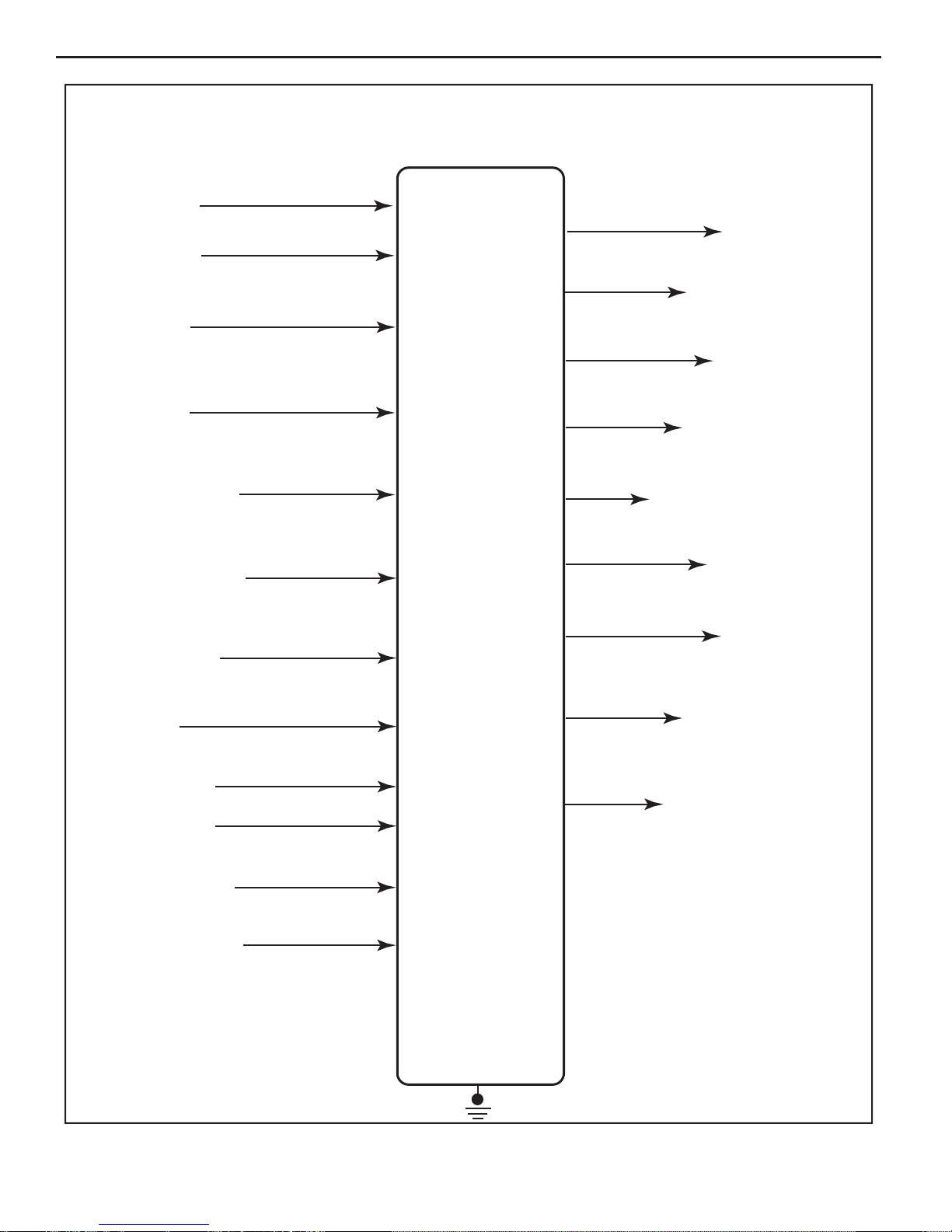
ECM Inputs and Sensor Descriptions
Figure 2-5 lists the data sensors, switches, and other inputs
used by the ECM to control its various systems. Although
we will not cover them all in great detail, there will be a
brief description of each.
Input Components
The ECM monitors the input components for circuit
continuity and out-of-range values. This includes
performance checking. Performance checking refers to
indicating a fault when the signal from a sensor does not
seem reasonable, such as a throttle position (TP) sensor
that indicates high throttle position at low engine loads or
MAP voltage. The input components may include, but are
not limited to, the following sensors:
• Intake air temperature (IAT) sensor (5.0/5.7L only)
• Crankshaft position (CKP) sensor
• Camshaft position (CMP) sensor
• Knock sensor(s) (KS)
• Throttle position (TP) sensor
• Engine coolant temperature (ECT) sensor
• Manifold absolute pressure (MAP) sensor
Output Components
Diagnose the output components for the proper response
to ECM commands. Components where functional
monitoring is not feasible, will be monitored for circuit
continuity and out-of-range values, if applicable.
Output components to be monitored include, but are not
limited to, the following circuits:
• The malfunction indicator lamp (MIL) control
• The check gauges lamp control
• The general warning 2 (low oil pressure) lamp
control
MEFI 4 - PCM
2 - 6 ECM and Sensors 5.0/5.7/6.0/8.1L
MEFI INPUTS AND OUTPUTS
INPUTS
BATTERY 12V
IGNITION 12V
CRANKSHAFT
POSITION
SENSOR (RPM)
CAMSHAFT
POSITION
SENSOR
THROTTLE POSITION
(TP) SENSOR
MANIFOLD ABSOLUTE
PRESSURE(MAP)
(TYPICAL)
E
L
E
C
T
R
O
N
I
C
OUTPUTS
FUEL INJECTORS
MULTIPLE
IGNITION CONTROLS (IC)
FUEL PUMP RELAY
IDLE AIR CONTROL (IAC)
OPERATOR INFORMATION
LAMPS/BUZZERS
SERIAL DATA (ECM
COMMUNICATION)
ENGINE COOLANT
TEMPERATURE (ECT)
SENSOR
INTAKE AIR
TEMPERATURE (IAT) (5.0/5.7L only)
KNOCK SENSOR 1
KNOCK SENSOR 2
(6.0/8.1L only)
DIAGNOSTIC ENABLE
GENERAL WARNING 2
(OIL PRESSURE)
C
O
N
T
R
O
L
M
O
D
U
L
E
V- REFERENCE
(5 VOLT OUTPUT
TO SENSORS)
MALFUNCTION INDICATOR
LAMP (MIL)
DEPSPOWER
(12 VOLT OUTPUT
TO SENSORS)
Figure 2-5 - ECM Inputs and Outputs (Typical)
MEFI 4 - PCM
2-13-04
MS 11699
5.0/5.7/6.0L/8.1L ECM and Sensors 2 - 7
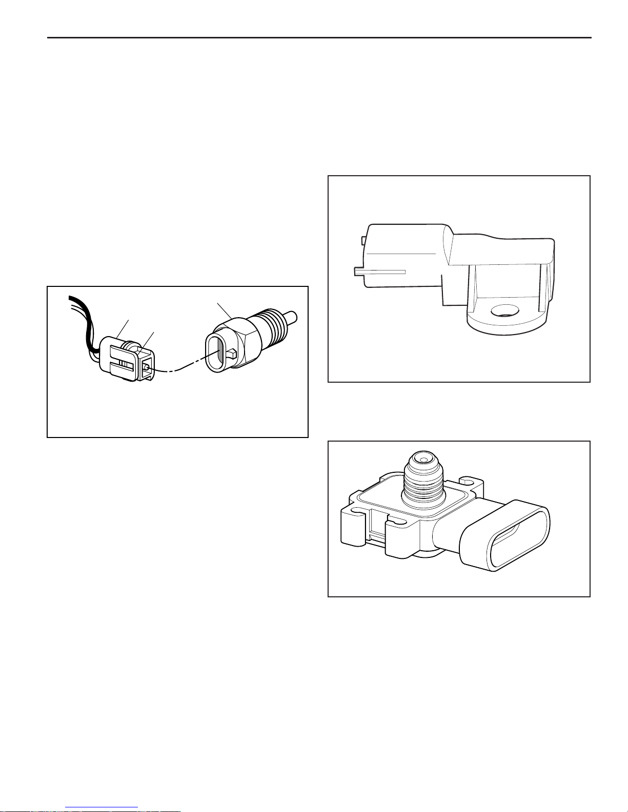
Engine Coolant Temperature (ECT) Sensor
The engine coolant temperature (ECT) sensor is a
thermistor (a resistor which changes value based on
temperature) mounted in the engine coolant stream. Low
coolant temperature produces a high resistance (100,000
ohms at -40°C/-40°F) while high temperature causes low
resistance (70 ohms at 130°C/266°F).
The ECM supplies a 5 volt signal to the ECT sensor
through a resistor in the ECM and measures the voltage.
The voltage will be high when the engine is cold, and low
when the engine is hot. By measuring the v oltage, the ECM
calculates the engine coolant temperature. Engine coolant
temperature affects most systems the ECM controls.
A hard fault in the engine coolant sensor circuit should
set DTC 14 or DTC 15; an intermittent fault may or may
not set a DTC. The DTC “Diagnostic Aids” also contains
a chart to check for sensor resistance values relative
to temperature.
3
1
2
The ECM supplies a 5 volt reference voltage to the MAP
sensor. As the manifold pressure changes, the electrical
resistance of the MAP sensor also changes. By monitoring
the sensor output voltage, the ECM knows the manifold
pressure. A higher pressure, low vacuum (high voltage)
requires more fuel. A lower pressure, high vacuum (low
voltage) requires less fuel. The ECM uses the MAP sensor
to control fuel delivery and ignition timing. A failure in the
MAP sensor circuit should set a DTC 33 or DTC 34.
1HARNESS CONNECTOR
2LOCKING TAB
3SENSOR
Figure 2-6 - Engine Coolant Temperature (ECT) Sensor
8-24-94
RS 22189
Manifold Absolute Pressure (MAP) Sensor
The Manifold Absolute Pressure (MAP) sensor is a
pressure transducer that measures the changes in the
intake manifold pressure. The pressure changes as a result
of engine load and speed change, and the MAP sensor
converts this into a voltage output.
A closed throttle on engine coastdown would produce
a relatively low MAP output voltage, while a wide open
throttle would produce a high MAP output voltage. This
high output voltage is produced because the pressure
inside the manifold is almost the same as outside the
manifold, so you measure almost 100% of outside air
pressure. MAP is the opposite of what you would measure
on a vacuum gauge. When manifold pressure is high,
vacuum is low, causing a high MAP output voltage.
The MAP sensor is also used to measure barometric
pressure under certain conditions, which allows the ECM
to automatically adjust for different altitudes.
Figure 2-7 - Manifold Absolute Pressure (MAP) Sensor/
Intake Air Temperature (IAT) Sensor
(Used On 5.0/5.7L Engines)
I 22312
Figure 2-8 - Manifold Absolute Pressure (MAP) Sensor
(Used On 6.0/8.1L Engines)
MEFI 4 - PCM
2 - 8 ECM and Sensors 5.0/5.7/6.0/8.1L
Throttle Position (TP) Sensor
The Throttle Position (TP) sensor is a potentiometer
connected to the throttle shaft on the throttle body.
By monitoring the voltage on the signal line, the ECM
calculates throttle position. As the throttle valve angle is
changed (accelerator pedal moved), the TP sensor signal
also changes. At a closed throttle position, the output of the
TP sensor is low. As the throttle valve opens, the output
increases so that at Wide Open Throttle (WOT), the output
voltage should be above 4 volts.
The ECM calculates fuel delivery based on throttle valve
angle (driver demand). A broken or loose TP sensor
may cause intermittent bursts of fuel from an injector
and unstable idle because the ECM thinks the throttle is
moving. A hard failure in the TP sensor circuit should set
either a DTC 21 or DTC 22. Once a DTC is set, the ECM
will use a calibratible default value for throttle position and
some engine performance will return.
Intake Air Temperature (IAT) Sensor (5.0/5.7L)
The Intake Air Temperature (IAT) sensor is a thermistor
which changes value based on the temperature of air
entering the engine (Figure 2-12). Low temperature
produces a high resistance (100,000 ohms at -40°C/-40°F)
while high temperature causes low resistance (70 ohms
at 130°C/266°F).
The ECM supplies a 5 volt signal to the sensor through a
resistor in the ECM and measures the voltage. The voltage
will be high when the incoming air is cold, and low when
the incoming air is hot. By measuring the voltage, the
ECM calculates the incoming air temperature. The IAT
sensor signal is used to determine spark timing based on
incoming air density.
The scan tool displays temperature of the air entering the
engine, which should read close to ambient air temperature
when engine is cold, and rise as engine compartment
temperature increases. If the engine has not been run for
several hours (overnight), the IAT sensor and ECT sensor
temperatures should read close to each other. A failure in
the IAT sensor circuit should set DTC 23 or DTC 25.
1
2
1 THROTTLE POSITION (TP) SENSOR
2 TP SENSOR ATTACHING SCREW
Figure 2-10 - Throttle Position (TP) Sensor (Typical)
C
B
A
2
CONTROL
MODULE
1
RS 22191
Figure 2-12 - Manifold Absolute Pressure (MAP) Sensor/
Intake Air Temperature (IAT) Sensor
(Used On 5.0/5.7L Engines)
Ignition Control (IC) Reference
The Ignition Control (IC) reference (RPM signal) is supplied
to the ECM by way of the crankshaft position sensor. This
pulse counter type input creates the timing signal for the
pulsing of the fuel injectors, as well as the IC functions.
This signal is used for a number of control and testing
functions within the ECM.
1 THROTTLE POSITION (TP) SENSOR
2 THROTTLE VALVE
Figure 2-11 - Throttle Position (TP) Sensor (Typical)
MEFI 4 - PCM
RS 22192
5.0/5.7/6.0L/8.1L ECM and Sensors 2 - 9
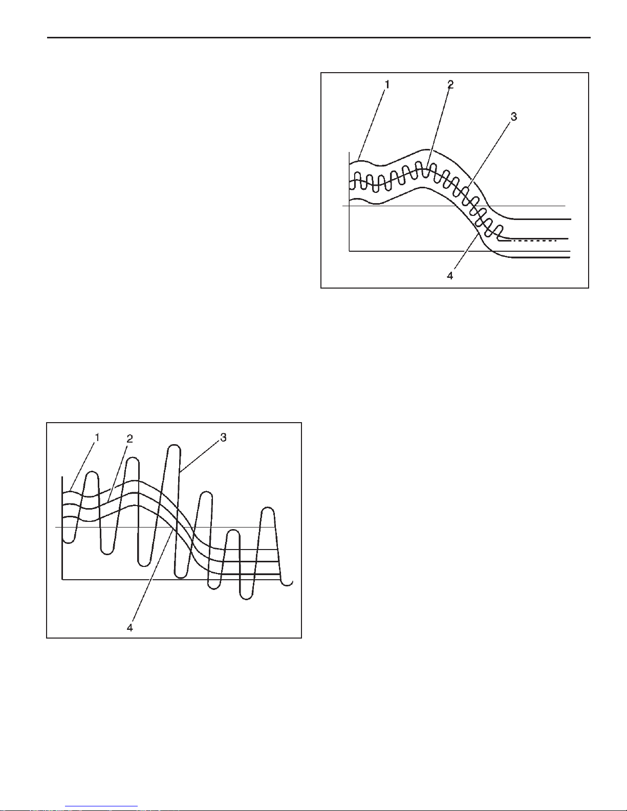
Knock Sensor (KS) System Description
Purpose:
To control spar k knock (detonation), a knock sensor
(KS) system is used. This system is designed to retard
spark timing when excessive spark knock is detected
in the engine. The KS system allows the engine to use
maximum spark advance for optimal driveability and fuel
economy under all operating conditions.
Operation:
The ECM uses a knock sensor(s) to detect abnormal
vibration in the engine (detonation/spark knock).
Mounted on the engine block, the knock sensor(s)
produces an AC voltage signal at all engine speeds and
loads. The ECM then adjusts the spar k timing based on
the amplitude and frequency of the KS signal. The ECM
uses the KS signal to calculate an average voltage.
Then, the ECM assigns a voltage range above and
below the average voltage value. The ECM checks the
KS and related wiring by comparing the actual knock
signal to the assigned voltage range. A normal KS
signal should vary outside the assigned voltage range
as shown in the NORMAL KS fi gure. If the ECM detects
a KS signal within the assigned voltage range as shown
in the ABNORMAL KS fi gure, the applicable DTC will
set.
Abnormal Knock Sensor Signal
Legend
1. Upper fail region
2. Knock sensor calculated average
3. Knock sensor signal
4. Lower fail region
245257
Normal Knock Sensor Signal
245253
Discrete Switch Inputs
Several discrete switch inputs are utilized by the MEFI
system to identify abnormal conditions that may affect
engine operation. Pull-up and pull-down type switches are
currently used in conjunction with the ECM to detect critical
conditions to engine operation.
If a switch changes states from its normal at rest position,
that is, normally closed to open, or normally open to closed,
the ECM senses a change in voltage and responds by
entering Power reduction mode.
This engine protection feature allows the operator normal
engine operations up to 2500 RPM, but disables half the
fuel injectors until the engine drops below 1200 RPM.
Then normal engine operation is restored until the RPM
limit is exceeded. This feature allows the operator a safe
maneuvering speed while removing the possibility of high
RPM engine operation until the problem is corrected.
Switches that may be used with the MEFI system to detect
critical engine operation parameters are:
• Oil Pressure
MEFI 4 - PCM
2 - 10 ECM and Sensors 5.0/5.7/6.0/8.1L
Diagnosis
Engine Control Module (ECM)
To read and clear diagnostic trouble codes, use a scan tool
or Diagnostic Trouble Code (DTC) tool.
Important: Use of a scan tool is recommended to clear
diagnostic trouble codes from the ECM memory . Diagnostic
trouble codes can also be cleared by using the DTC tool.
Since the ECM can have a failure which may affect more
than one circuit, following the diagnostic procedures will
determine which circuit has a problem and where it is.
If a diagnostic procedure indicates that the ECM connections
or ECM is the cause of a problem and the ECM is replaced,
but does not correct the problem, one of the following
may be the reason:
• Check for good ECM power and grounds.
• There is a problem with the ECM terminal connections.
The diagnostic table will say ECM connections or
ECM. The terminals may have to be removed from the
connector in order to check them properly.
• EEPROM program is not correct for the application.
Incorrect components may cause a malfunction and
may or may not set a DTC.
• The problem is intermittent. This means that the
problem is not present at the time the system is being
checked. In this case, refer to the Symptoms portion
of the manual and make a careful physical inspection
of all portions of the system involved.
• Shorted relay coil or harness. Relays are turned
“ON” and “OFF” by the ECM using internal electronic
switches called drivers. A shorted relay coil or harness
may not damage the ECM but will cause the relay
to be inoperative.
On-Board Service
Engine Control Module (ECM) Replacement
Notice: When replacing the ECM, the ignition must be
“OFF” and disconnect the battery before disconnecting or
reconnecting the ECM “J1” and “J2” connectors to prevent
internal damage to the ECM.
Notice: T o prev ent possible electrostatic discharge damage
to the ECM, do not touch the connector pins. The ECM is
an electrical component. Do Not soak in any liquid cleaner
or solvent, as damage may result.
Remove or Disconnect
1. Negative battery cable.
2. “J1” and “J2” connectors from ECM.
3. The ECM mounting screws.
4. ECM from mounting bracket.
Important
• Make sure the new ECM has the same part number
and service number as the old ECM, to insure proper
engine performance.
Install or Connect
1. New ECM to mounting bracket.
2. The ECM mounting screws. Torque to 10-14 N•m
(88-124 lb in).
3. “J1” and “J2” connectors to ECM.
4. Negative battery cable.
MEFI 4 - PCM
J2J1
MEFI3004
Figure 2-13 - Engine Control Module (ECM)

5.0/5.7/6.0L/8.1L ECM and Sensors 2 - 11
System Relay Replacement
Removal Procedure
1. Tur n the ignition OFF.
2. Remove the retainer.
3. Disconnect the system relay electrical connector.
4. Remove the system relay.
Important: The system relay is an electrical component.
Do Not soak in any liquid or solvent as damage may
result.
Installation Procedure
1. Install the system relay.
2. Reconnect the system electrical connector.
3. Install the retainer clip.
mefi 4337
Fuel Pump Relay Replacement
Removal Procedure
1. Turn the ignition OFF.
2. Remove the retainer.
3. Disconnect the fuel pump relay electrical connector.
4. Remove the fuel pump relay.
Important: The fuel pump relay is an electrical
component. Do Not soak in any liquid or solvent as
damage may result.
Installation Procedure
1. Install the fuel pump relay.
2. Reconnect the fuel pump relay electrical connector.
3. Install the retainer clip.
mefi 4337
Starter Relay Replacement
Removal Procedure
1. Turn the ignition OFF.
2. Remove the retainer.
3. Disconnect the star ter relay electrical connector.
4. Remove the starter relay.
Important: The starter relay is an electrical component.
Do Not soak in any liquid or solvent as damage may
result.
Installation Procedure
1. Install the starter relay.
2. Reconnect the star ter relay electrical connector.
3. Install the retainer clip.
mefi 4337
MEFI 4 - PCM

2 - 12 ECM and Sensors 5.0/5.7/6.0/8.1L
Engine Coolant Temperature (ECT) Sensor
Replacement
Notice: Care must be taken when handling the ECT
sensor. Damage to the sensor will affect proper operation
of the MEFI system.
Remove or Disconnect
1. Turn OFF the ignition.
2. Drain the cooling system below the level of the ECT
sensor (if necessary).
3. Disconnect the ECT electrical connector.
4. Remove the ECT sensor.
mefi 4333
Installation Procedure
Important: Coat ECT sensor threads with Tefl on tape
sealant prior to installation.
1. Install the ECT sensor.
Tighten
Tighten the ECT sensor to 20 N•m (15 lb ft).
2. Reconnect the ECT electrical connector.
3. Refi ll the cooling system (if necessary).
MEFI 4 - PCM
mefi 4333

5.0/5.7/6.0L/8.1L ECM and Sensors 2 - 13
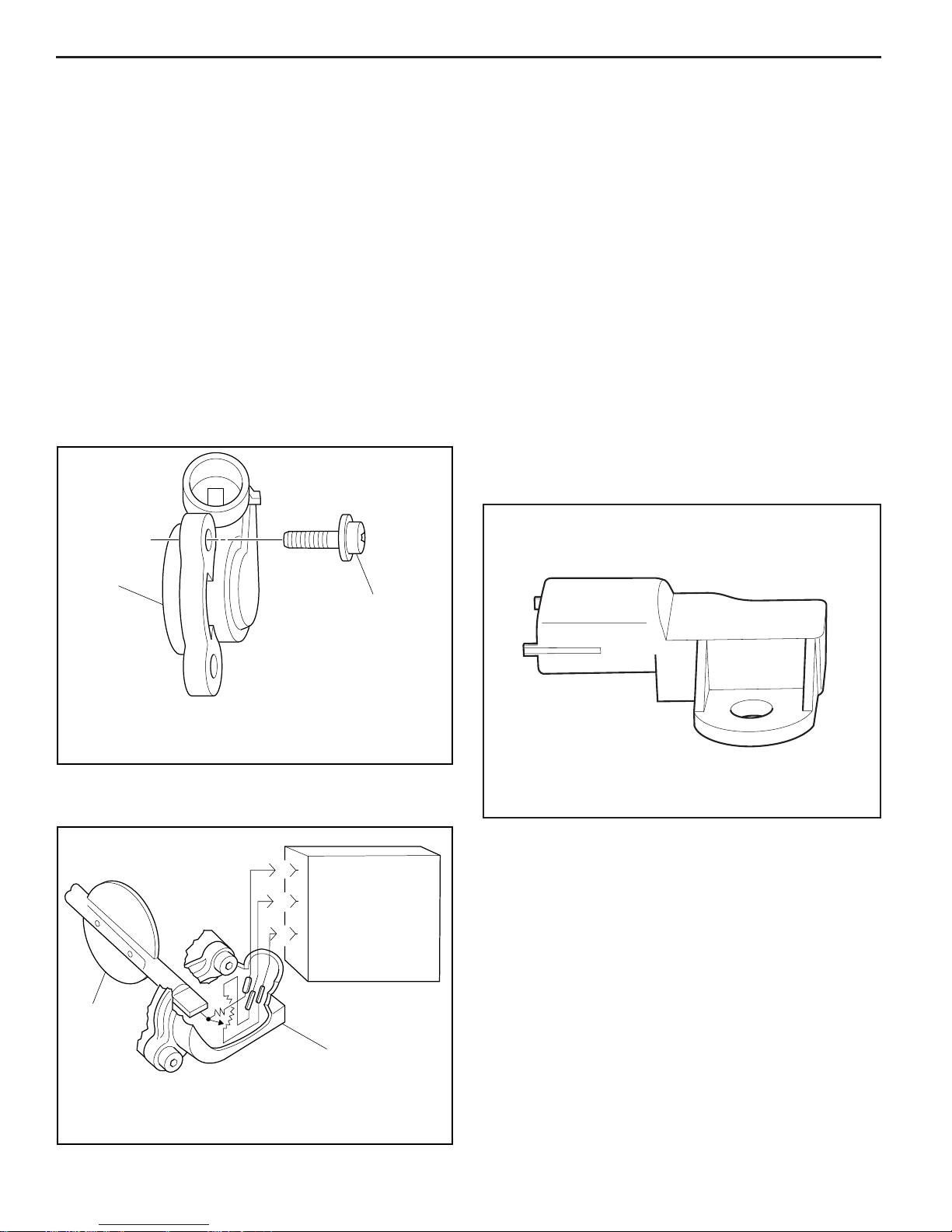
Manifold Absolute Pressure (MAP) / Intake
Air Temperature (IAT) Sensor Replacement
(5.0/5.7L)
Removal Procedure
1. Remove the MAP sensor retaining stud.
2. Remove the MAP sensor from the intake manifold.
3. Inspect the MAP sensor seal for wear or damage and
replace as necessary.
map rr
Installation Procedure
Important: Lightly coat the MAP sensor seal with rubber
lubricant before installing the sensor. The lubricant should
be applied with a sponge or brush. To prevent blockage,
avoid dipping the sensor port directly into the lubricant.
1. Install the MAP sensor.
2. Install the MAP sensor retaining stud.
Tighten
Tighten the MAP sensor retaining stud to 12 N•m
(106 lb in).
3. Connect the manifold absolute pressure (MAP) sensor
electrical connector.
map rr
MEFI 4 - PCM

2 - 14 ECM and Sensors 5.0/5.7/6.0/8.1L
Manifold Absolute Pressure (MAP) Sensor
Replacement (6.0/8.1L)
1
684798
Removal Procedure
1. Disconnect the manifold absolute pressure (MAP)
sensor electrical connector (1).
2. Remove the MAP sensor retaining bolt and washer
(1).
3. Remove the MAP sensor (3) from the intake manifold
(2).
4. Inspect the MAP sensor seal for wear or damage and
replace as necessary.
MEFI 4 - PCM
684801
Installation Procedure
Important: Lightly coat the MAP sensor seal with rubber
lubricant before installing the sensor. The lubricant should
be applied with a sponge or brush. To prevent blockage,
avoid dipping the sensor port directly into the lubricant.
1. Install the MAP sensor (3).
2. Install the MAP sensor retaining bolt and washer (1).
Tighten
Tighten the MAP sensor retaining bolt to 12 N•m
(106 lb in).
684801

5.0/5.7/6.0L/8.1L ECM and Sensors 2 - 15
3. Connect the MAP sensor electrical connector (1).
1
684798
MEFI 4 - PCM

2 - 16 ECM and Sensors 5.0/5.7/6.0/8.1L
Throttle Position (TP) Sensor
Remove or Disconnect
1. Flame arrestor.
2. TP sensor electrical connector.
3. TP sensor attaching screws (1).
4. TP sensor (2).
1
Important
• The TP sensor is an electrical component. Do Not
soak in any liquid cleaner or solvent, as damage
may result.
• If replacing TP sensor, install new screws that are
2
PS19190
1
supplied with the TP sensor service package.
Install or Connect
1. TP sensor over throttle shaft.
2. With throttle valve in the normal closed position (idle),
install TP sensor on throttle body assembly, making
sure TP sensor pickup lever lines up with the tang on
the throttle actuator lever.
3. TP sensor attaching screws. Torque to 2 N•m (18
lb in).
4. TP sensor electrical connector.
5. Flame arrestor.
2
PS19190
MEFI 4 - PCM

5.0/5.7/6.0L/8.1L ECM and Sensors 2 - 17
Idle Air Control (IAC) Valve
Remove or Disconnect
1. Flame arrestor.
2. IAC electrical connector.
1
3. IAC valve attaching screws (1).
4. IAC valve (2).
2
Notice: On IAC valves that have been in service, Do Not
push or pull on the IAC valve pintle. The force required
to move the pintle may damage the threads on the worm
drive. Also, Do Not soak IAC valve in any liquid cleaner or
solvent, as damage may result.
Clean and Inspect
• Clean IAC valve O-ring sealing surface, pintle valve
seat and air passage.
– Use carburetor cleaner to remove carbon deposits.
Do Not use a cleaner that contains methyl ethyl
ketone, an extremely strong solvent, and not
necessary for this type of deposit.
– Shiny spots on the pintle or seat are normal,
and do not indicate misalignment or a bent pintle
shaft.
Important
• If installing a new IAC valve, be sure to replace with
an identical part number. IAC valve pintle shape and
diameter are designed for the specifi c application.
Measure (If installing a new IAC valve)
• Distance between tip of IAC valve pintle and mounting
surface.
– If greater than 28 mm, use finger pressure to
slowly retract the pintle. The force required to
retract the pintle of a new valve will not cause
damage to the valve.
➤
A
➤
B
➤
➤
1 O-RING - IAC VALVE
2 IAC VALVE ATTACHING SCREW
A DISTANCE OF PINTLE EXTENSION
B DIAMETER OF PINTLE
1
M4085
2
8-24-94
RS 22181
Install or Connect
1. New O-ring on IAC valve and lubricate.
Notice: New IAC valves have been preset at the factory
and should not require any adjustment.
2. IAC valve to throttle body using attaching screws.
Torque to 3.2 N•m (28 lb in).
3. IAC valve electrical connector.
4. Reset IAC valve pintle position:
• Turn ignition “OFF” for 10 seconds.
• Start and run engine for 5 seconds.
• Ignition “OFF” for 10 seconds.
• Restart engine and check for proper idle.
1
2
M4085
MEFI 4 - PCM

2 - 18 ECM and Sensors 5.0/5.7/6.0/8.1L
Knock Sensor (KS) (5.0/5.7L)
Remove or Disconnect
2
1. Negative battery cable.
2. Knock sensor electrical connector.
3. Knock sensor from engine block.
FRT
1
1 KNOCK SENSOR
2 ENGINE BLOCK
RS 22182
8-24-94
RS 22183
Install or Connect
Important
• If installing a new knock sensor, be sure to replace
with an identical part number.
• When installing knock sensor, be sure to install in the
same location removed from.
• If installing knock sensor in water jacket, use Tefl on
sealer.
1. Knock sensor into engine block. Be sure threads are
clean. Torque to 15-22 N•m (11-16 lb ft).
2. Knock sensor electrical connector.
3. Negative battery cable.
MEFI 4 - PCM
Knock Sensors (KS) (6.0L)
Remove or Disconnect
1. Remove the intake manif old. Ref er to Intake Manif old
Replacement in Engine Mechanical - 6.0L.
2. Gently pry up the rubber covers.
3. Disconnect the knock sensor electrical connectors.

5.0/5.7/6.0L/8.1L ECM and Sensors 2 - 19
4. Remove the knock sensors.
Install or Connect
Important
• If installing a new knock sensor, be sure to replace
with an identical part number.
• When installing knock sensor, be sure to install in the
same location removed from.
1. Knock sensors into engine block. Be sure threads are
clean. Torque to 20 N•m (15 lb ft).
2. Connect the knock sensor electrical connectors.
3. Push down on the rubber covers.
4. Install the intake manifold. Refer to Intake Manifold
Replacement in Engine Mechanical - 6.0L.
MEFI 4 - PCM

2 - 20 ECM and Sensors 5.0/5.7/6.0/8.1L
Torque Specifi cations
Fastener Tightening Specifi cations (5.0/5.7L)
Application N•m Lb Ft Lb In
ECM Mounting Screws 10-14 88-124
ECT Sensor 12 108
MAP/IAT Sensor Attaching Stud 5-7 44-62
TP Sensor Attaching Screws 2 18
IAC Valve Attaching Screws 3.2 28
Knock Sensor 15-22 11-16
Fastener Tightening Specifi cations (6.0/8.1L)
Application N•m Lb Ft Lb In
ECM Mounting Screws 10-14 88-124
ECT Sensor 12 108
MAP Sensor Attaching Screw 5-7 44-62
TP Sensor Attaching Screws 2 18
IAC Valve Attaching Screws 3.2 28
Knock Sensors 20 15
MEFI 4 - PCM

5.0/5.7L Fuel Metering System 3A - 1
Marine Electronic Fuel Injection (MEFI)
Section 3A
Fuel Metering System - 5.0/5.7L
This section describes how the fuel metering system operates, and provides a description of components used on the
Marine Electronic Fuel Injection equipped engines. The fuel metering system information described in this section is
limited to the 5.0/5.7L. All other systems will be detailed in a separate section.
Contents
General Description ..........................................Page 2
Purpose......................................................... Page 2
Modes of Operation ......................................Page 2
Starting Mode......................................... Page 2
Clear Flood Mode...................................Page 2
Run Mode...............................................Page 2
Acceleration Mode..................................Page 2
Fuel Cutoff Mode....................................Page 2
Power Reduction Mode.......................... Page 2
Fuel Metering System Components .............Page 2
Quick-Connect Fittings.................................. Page 2
Fuel Supply Components (FCC System) .... Page 3
Fuel Pump Electrical Circuit ......................... Page 4
Fuel Rail Assembly....................................... Page 4
Fuel Injectors..........................................Page 4
Pressure Regulator Assembly................Page 5
Throttle Body Assembly................................Page 5
Idle Air Control (IAC) Valve.....................Page 6
Diagnosis ...........................................................Page 6
On-Board Service ................................................Page 6
Fuel Control On-Board Service ...................... Page 7
Fuel Pressure Relief Procedure......................Page 7
Flame Arrestor................................................ Page 7
Throttle Body Assembly..................................Page 8
Quick Connect Fitting(s) Service
(Metal Collar) ..................................................Page 9
Fuel Rail Assembly....................................... Page 11
Fuel Injectors ................................................Page 13
Fuel Pressure Regulator Assembly.............. Page 14
Fuel Control Cell (FCC)................................ Page 15
Low-Pressure Fuel Pump .............................Page 18
Fuel Pump Relay ..........................................Page 18
Torque Specifi cations ....................................... P age 19
MEFI 4 - PCM

3A - 2 Fuel Metering System 5.0/5.7L
General Description
Purpose
The function of the fuel metering system is to deliver the
correct amount of fuel to the engine under all operating
conditions. Fuel is delivered to the engine by individual
fuel injectors mounted in the intake manifold near each
cylinder.
Modes Of Operation
The ECM looks at inputs from several sensors to determine
how much fuel to give the engine. The fuel is delivered under
one of several conditions, called “modes.” All the “modes”
are controlled by the ECM and are described below.
Starting Mode
When the ignition switch is turned to the crank position, the
ECM turns the fuel pump relay “ON,” and the fuel pump
builds up pressure. The ECM then checks the ECT, MAP
and TP sensors, and determines the proper air/fuel ratio
for starting. The ECM controls the amount of fuel delivered
in the starting mode by changing how long the injectors
are turned “ON” and “OFF.” This is done by “pulsing” the
injectors for very short times.
Clear Flood Mode
If the engine fl oods, it can be cleared by opening the throttle
to 100% (wide open throttle) during cranking. The ECM then
shuts down the fuel injectors so no fuel is delivered. The
ECM holds this injector rate as long as the throttle stays
at 100%, and the engine speed is below 300 RPM. If the
throttle position becomes less than 100%, the ECM returns
to the starting mode.
Run Mode
When the engine is fi rst started and RPM is above 300
RPM, the system operates in the run mode. The ECM will
calculate the desired air/fuel ratio based on these ECM
inputs: RPM, ECT and MAP. Higher engine loads (MAP
input) and colder engine temperatures (ECT input) require
more fuel, or a richer air/fuel ratio.
Acceleration Mode
The ECM looks at rapid changes in TP sensor and MAP,
and provides extra fuel by increasing the injector pulse
width.
Fuel Cutoff Mode
No fuel is delivered by the injector when the ignition is
“OFF,” to prevent dieseling. Also, injector pulses are not
delivered if the ECM does not receive distributor reference
pulses, which means the engine is not running. The fuel
cutoff mode is also enabled at high engine RPM, as an
overspeed protection for the engine. When fuel cutoff is
in effect due to high RPM, injector pulses will resume
after engine RPM drops below the maximum OEM RPM
specifi cation (Rev Limit).
Power Reduction Mode
Power reduction mode is a function of the ECM that
reduces
engine power under certain conditions. Power reduction will
disable one fuel injector driver when the engine speed goes
above 2500 rpm, and enable the fuel injector driver when the
engine speed drops below 1200 rpm. Power reduction may
be active for the following conditions:
• Engine coolant temperature too high
• Low oil pressure
• Transmission temperature too high (if applicable)
Fuel Metering System Components
The fuel metering system (Figure 3-1) is made up of the
following parts:
Fuel supply components (fuel tank, pump, lines, fi lter).
•
Fuel pump electrical circuit.
•
Fuel rail assembly, including fuel injectors and pressure
•
regulator assembly.
Throttle body assembly, including an IAC valve and
•
TP sensor.
Quick-Connect Fittings
Quick-Connect fi ttings provide a simplifi ed means of
installing and connecting fuel system components. The
fi ttings consists of a unique female connector and a
compatible male pipe end. O-rings, located inside the
female connector, provide the fuel seal. Integral locking tabs
inside the female connector hold the fi ttings together.
Fuel Supply Components (FCC System)
The Fuel Control Cell (FCC) incorporates two (2) fuel pumps
to provide uninterrupted fl ow of fuel to your marine engine.
Fuel is fed into the FCC by a low-pressure, high volume
electric fuel pump. This pump fl ows fuel at a volume which
exceeds the fuel flow rate required of the high-pressure
pump by engine demands.
The high pressure pump, mounted inside the FCC bowl,
provides the necessary fuel pressure and volume to maintain
proper engine performance, and always has an ample
supply of fuel to meet the idle, cruise and acceleration fuel
requirements fo the engine.
The fuel pressure regulator, located on the fuel rail, controls
fuel pressure and maintains a constant pressure across the
fuel delivery system. Fuel not used by the engine, excess
fuel, is returned to the FCC canister.
The fuel delivered to the engine by the FCC is fi ltered by a
fi lter and water separator element, which surrounds the high
pressure pump inside the FCC bowl.
The fuel enters the FCC bowl from two (2) components,
the low-pressure pump (initial input) and the fuel pressure
regulator (unused recirculating). Fuel exits the FCC bowl at
two (2) locations, the high-pressure output to the fuel rail
and all excess fuel in the FCC bowl is routed back to the
fuel tank via a return line.
MEFI 4 - PCM

5.0/5.7L Fuel Metering System 3A - 3
PRESSURE
REGULATOR
FUEL RAIL ASSEMBLY
ENGINE
Fuel Control Cell Fuel System
LOW-
PRESSURE
FUEL
CONTROL
CELL
Figure 3-1 - Fuel Metering System (Typical)
FUEL
PUMP
FUEL
FILTER
FUEL
TANK
Figure 3-2 - Typical Fuel Control Cell (FCC)
Figure 3-3 - Low Pressure Fuel Pump
MEFI 4 - PCM

3A - 4 Fuel Metering System 5.0/5.7L
Fuel Pump Electrical Circuit
When the ignition switch is turned “ON,” the ECM turns
the fuel pump relay “ON” for two seconds causing the fuel
pump(s) to pressurize the MEFI fuel system.
When the ignition switch is turned to the crank position,
the ECM turns the fuel pump relay “ON” causing the fuel
pump to run.
If the ECM does not receive ignition reference pulses
(engine cranking or running), it shuts “OFF” the fuel pump
relay, causing the fuel pump to stop.
An inoperative fuel pump relay will result in an “Engine
Cranks But Will Not Run” condition.
Fuel Rail Assembly
The fuel rail (Figure 3-3) is mounted to the engine intake
manifold, and performs several functions. It positions the
injectors in the intake manifold, distributes fuel evenly to
the injectors, and integrates the fuel pressure regulator
into the fuel metering system.
Fuel Injectors
The fuel injector assembly is a solenoid-operated device,
controlled by the ECM, that meters pressurized fuel to a
single engine cylinder (Figure 3-4). The ECM energizes
the injector solenoid, which opens a ball valve, allowing
fuel to fl ow past the ball valve, and through a recessed
fl ow director plate. The director plate has six machined
holes that control the fuel fl ow, generating a conical spray
pattern of fi nely atomized fuel at the injector tip. Fuel is
directed at the intake valve, causing it to become further
atomized and vaporized before entering the combustion
chamber.
An injector that is stuck partly open would cause loss
of pressure after engine shut down. Consequently, long
cranking times would be noticed. Dieseling could also
occur, because some fuel could be deliv ered to the engine
after the ignition is turned “OFF.” A fuel injector that does
not open, may cause a “no-start” or a misfi re.
11
Figure 3-3 - Fuel Rail Assembly
10
9
8
7
6
1 SOLENOID ASSEMBLY
2 SPACER AND GUIDE
ASSEMBLY
3 CORE SEAT
4 BALL VALVE
5 SPRAY TIP
6 DIRECTOR PLATE
1
2
3
4
5
7 SPRAY HOUSING
8 CORE SPRING
9 SOLENOID HOUSING
10 SOLENOID
11 FUEL INLET FILTER
4-11-96
9P 0413-SY
MEFI 4 - PCM
Figure 3-4 - Fuel Injector Assembly (Typical)

5.0/5.7L Fuel Metering System 3A - 5
Pressure Regulator Assembly
The pressure regulator is a diaphragm-operated relief
valve with fuel pump pressure on one side, and regulator
spring pressure and intake manifold vacuum on the other
side (Figure 3-5). The regulator’s function is to maintain
a constant pressure differential across the injectors at all
times. The pressure regulator compensates for engine load
by increasing fuel pressure as engine vacuum drops.
With the ignition “ON,” engine “OFF” (zero vacuum),
fuel pressure at the pressure test connection should be
284-325 kPa (41-47 psi). If the pressure is too low, poor
performance or a “no-start” may result. If pressure is too
high, excessive odor may result.
Throttle Body Assembly
The throttle body assembly is attached to the intake
manifold air plenum, and is used to control air fl ow into the
engine, thereby controlling engine output (Figure 3-6). The
throttle plates within the throttle body are opened by the
driver through the throttle controls. During engine idle, the
throttle plates are closed, and air fl ow control is handled by
the Idle Air Control (IAC) valve, described below.
The throttle body also provides the location for mounting
the TP sensor and for sensing changes in engine vacuum
due to throttle plates position.
1
8
7
6
5
1 COVER
2 VACUUM CHAMBER
(VACUUM SOURCE TUBE NOT SHOWN)
3 O - RING SEAL
4 FUEL PRESSURE REGULATOR VALVE
5 BASE ASSEMBLY
6 FILTER SCREEN (IF EQUIPPED)
7 DIAPHRAGM
8 SPRING
2
3
4
4-11-96
NA 0493-SY
Figure 3-6 - Throttle Body Assembly
Figure 3-5 - Pressure Regulator Assembly (Typical)
MEFI 4 - PCM

3A - 6 Fuel Metering System 5.0/5.7L
Idle Air Control (IAC) Valve
The purpose of the IAC valve assembly (Figures 3-7 and
3-8) is to control engine idle speed, while preventing stalls
due to changes in engine load.
The IAC valve, mounted to the throttle body, controls
bypass air around the throttle plates (Figure 3-7). By
moving a conical valve known as a pintle, IN, towards the
seat (to decrease air fl ow); or OUT, away from the seat (to
increase air fl ow), a controlled amount of air moves around
the throttle plates. If RPM is too low, more air is bypassed
around the throttle plates to increase it. If RPM is too
high, less air is bypassed around the throttle plates to
decrease it.
The ECM moves the IAC valve in small steps. These can
be monitored by scan tool test equipment, which plugs into
the Data Link Connector (DLC).
During idle, the proper position of the IAC valve is calculated
by the ECM, based on battery voltage, coolant temperature
and engine RPM. If the RPM drops below specifi cation
and the throttle plates are closed, the ECM senses a
near stall condition and calculates a new valve position
to prevent stalling.
Engine idle speed is a function of total air fl ow into
•
the engine based on IAC valve pintle position plus
throttle plates opening.
1
2
“Controlled” idle speed is programmed into the ECM,
•
which determines the correct IAC valve pintle position
to maintain the desired idle speed for all engine
operating conditions and loads.
The minimum air rate is set at the factory with a stop
•
screw . This setting allows enough air fl ow by the throttle
plates to cause the IAC valve pintle to be positioned
at a calibrated number of steps (counts) from the seat,
during “controlled” idle operation. This minimum air
rate setting should not be altered by turning the stop
screw or bending the linkage. Improper idle control
will result.
➤
➤
A
➤
B
➤
1 O-RING - IAC VALVE
2 IAC VALVE ATTACHING SCREW
A DISTANCE OF PINTLE EXTENSION
B DIAMETER OF PINTLE
Figure 3-8 - Flange Mounted Type IAC Valve
1
2
8-24-94
RS 22181
A
4
B
1 IDLE AIR CONTROL (IAC) VALVE
2 THROTTLE BODY ASSEMBLY
3 THROTTLE VALVE
4 IAC VALVE PINTLE
A ELECTRICAL INPUT SIGNAL
B AIR INLET
Figure 3-7 - IAC Valve Air Flow Diagram
3
8-25-94
RS 22193
Diagnosis
If the Engine Cranks But Will Not Run or immediately
stalls, Table A-3 of the Diagnosis section must be used
to determine if the failure is in the ignition system or the
fuel system.
On-Board Service
Caution:
To reduce the risk of fi re and personal injury, relieve
fuel system pressure before servicing fuel system
components.
After relieving fuel pressure, a small amount of fuel may
be released when servicing fuel lines or connections.
To reduce the chance of personal injury, cover fuel
line fi ttings with a shop towel before disconnecting
to catch any fuel that may leak out. Place the towel
in an approved container when disconnection is
completed.
MEFI 4 - PCM

5.0/5.7L Fuel Metering System 3A - 7
Fuel Control On-Board Service
The following is general inf ormation required when working
on the fuel system:
Always keep a dry chemical fire extinguisher near
•
the work area.
Fuel pipe fittings require new O-rings when
•
assembling.
Do not replace fuel pipe with fuel hose.
•
Always bleed off fuel pressure before servicing any
•
fuel system components.
Do not do any repairs on the fuel system until you
•
have read the instructions and checked the fi gures
relating the repair.
Observe all notices and cautions.
•
Fuel Pressure Relief Procedure
Tool Required:
J 34730-1, Fuel Pressure Gauge
Important
Refer to manufacturer’s warnings and cautions before
•
proceeding.
1. Disconnect negative battery cable to avoid possible
fuel discharge if an accidental attempt is made to
start the engine.
2. Loosen fuel filler cap to relieve any tank vapor
pressure.
3. Connect fuel pressure gauge J 34730-1 to fuel pressure
connector assembly. Wrap a shop towel around fi tting
while connecting the gauge to avoid any spillage.
4. Install bleed hose into an approved container and open
valve to bleed system pressure. Fuel connections are
now safe for servicing.
5. Drain any fuel remaining in the gauge into an approved
container.
Flame Arrestor
Remove or Disconnect
1. Flame arrestor retaining clamp.
2. Flame arrestor.
Inspect
Flame arrestor element for dust, dirt or water. Replace
•
if required.
Install or Connect
1. Flame arrestor to throttle body.
2. Flame arrestor retaining clamp to fl ame arrestor.
Figure 3-9 - Fuel Rail and Throttle Body Assemblies
MEFI 4 - PCM

3A - 8 Fuel Metering System 5.0/5.7L
Throttle Body Assembly
The throttle body assembly repair procedures cover
component replacement with the unit on the vessel.
However, throttle body replacement requires that the
complete unit be removed from the engine.
Clean
Important
Do not soak the throttle body in cold immersion type
•
cleaner. The throttle valves have a factory applied
sealing compound (DAG material is applied to outside
edge of each valve and throttle bore) to prevent air
bypass at closed throttle. Strong solvents or brushing
will remove the material. To clean the throttle body
following disassembly, use a spray type cleaner such
as GM X66-A or GM 1052626. Use a shop towel to
remove heavy deposits.
Notice: The TP sensor and the IAC valve are electrical
components and should NOT come in contact with solvent
or cleaner as they may be damaged.
Remove or Disconnect
1. Negative battery cable.
2. Flame arrestor.
3. Electr ical connectors from TP sensor and IAC valve.
4. Throttle cable.
5. Throttle body attaching bolts.
6. Throttle body assembly and fl ange gasket.
• Discard gasket.
Clean
Notice: Use care in cleaning old gasket material from
machined aluminum surfaces as sharp tools may damage
sealing surfaces.
Gasket sealing surfaces.
•
Install or Connect
1. Throttle body assembly with new fl ange gasket.
2. Throttle body attaching bolts. Torque to 15 N•m (11
lb.ft.).
3. Throttle cable to throttle body.
4. Electr ical connectors to TP sensor and IAC valve.
5. Flame arrestor.
6. Negative battery cable.
Inspect
With the engine “OFF,” check to see that the throttle
•
lever is free.
– Move the throttle lever to wide open throttle and
release.
Reset IAC valve pintle position:
Move throttle lever slightly.
•
Start and run engine for 5 seconds.
•
Turn ignition “OFF” for 10 seconds.
•
Restart engine and check for proper idle operation.
•
Inspect
Turn ignition switch to the “ON” position for 2 seconds,
•
then turn to the “OFF” position for 10 seconds. Turn
the ignition switch back to the “ON” position and check
for fuel leaks.
MEFI 4 - PCM

5.0/5.7L Fuel Metering System 3A - 9
Quick Connect Fitting(s) Service
Tools Required
J 37088-A Tool Set, Fuel Line Quick-Connect Separator
J 44581 Fuel Line Quick Connect Separator
Removal Procedure
1. Relieve the fuel system pressure before servicing
any fuel system connection. Refer to Fuel Pressure
Relief Procedure.
2. Remove the retainer from the quick-connect fi tting.
Caution: Wear safety glasses in order to avoid eye
damage.
3. Blow dirt out of the fi ttig using compressed air.
12776
4. Choose the correct tool from the tool set for the size of
the fi tting. Insert the tool into the female connector, then
push inward in order to release the locking tabs.
5. Pull the connection apart.
6. Use a clean shop towel in order to wipe off the male
pipe end.
7. Inspect both ends of the fi tting for dirt and burrs. Clean
or replace the components as required.
12780
12782
MEFI 4 - PCM

3A - 10 Fuel Metering System 5.0/5.7L
Installation Procedure
1. Apply a few drops of clean engine oil to the male
pipe end.
12784
2. Push both sides of the fi tting together in order to snap
the retaining tabs into place.
MEFI 4 - PCM
12786
3. Once installed, pull on both sides of the fi tting in order
to make sure the connection is secure.
4. Install the retainer to the quick-connect fi tting.
12787

5.0/5.7L Fuel Metering System 3A - 11
Fuel Rail Assembly
The fuel rails should be removed as an assembly with
the injectors attached. Names of component parts will
be found on the numbered list that accompanies the
disassembled view.
Notice:
Use care in removing the fuel rail assembly to prevent
•
damage to the injector electrical connector terminals
and the injector spray tips.
When removed, support the rail to avoid damaging
•
its components.
Prevent dirt and other contaminants from entering
•
open lines and passages. Fittings should be capped
and holes plugged during servicing.
Clean
Before removal, the fuel rail assemb ly may be cleaned
•
with a spray type engine cleaner, GM X-30A or
equivalent, following package instructions. Do Not
soak fuel rails in liquid cleaning solvent.
Caution: Safety glasses must be worn when using
compressed air as flying dirt particles may cause
eye injury.
Where injectors fi t into intake manifold, use compressed
•
air to blow out dirt from around injectors before
removing.
Remove or Disconnect
Caution: To reduce the risk of fi re and personal injury,
relieve the fuel system pressure before servicing the
fuel system components.
1. Negative battery cable.
2. Relieve fuel pressure.
• Refer to the “Fuel Pressure Relief Procedure.”
Fuel pressure connector assembly is located on
•
the fuel rail.
3. Fuel inlet line, follow procedure for Quick Connect
Fittings outlined in this section.
4. Fuel outlet line, follow procedure for Quick Connect
Fittings outlined in this section.
5. Vacuum line to fuel pressure regulator.
6. Electrical connectors from injectors.
7. Move wire harness out of way.
8. Four attaching screws for fuel rail.
9. Fuel rails as an assembly with injectors.
10. Injectors from rails, follow procedure for injector
removal outlined in this section.
Clean and Inspect
Notice: If it is necessary to remove rust or burrs from
the fuel rail pipes, use emery cloth in a radial motion with
the tube end to prevent damage to the O-ring sealing
surface.
Use a clean shop towel to wipe off male pipe ends.
•
Inspect all connectors for dirt and burrs. Clean or
•
replace components/assemblies as required.
Disassemble
Injector O-ring seal from spray tip end of each injector.
•
Discard O-ring seals.
Assemble
Lubr icate new injector O-ring seals with clean engine
•
oil and install on spray tip end of each injector.
Install or Connect
1. Lubricate injector O-ring seals and install injectors
following injector installation procedure outlined in
this section.
2. Fuel rails as an assembly with injectors onto intake
manifold.
If injectors are lined up properly they will slide into
•
place.
Push gently and evenly on rail to set injectors all
•
the way into their bores
3. Fuel rail attaching screws. Torque to 10 N•m (88
lb.in.).
4. Injector electrical connectors and secure harness
in place.
5. Vacuum line to fuel pressure regulator.
6. Fuel inlet line, follow procedure for Quick Connect
Fittings outlined in this section.
7. Fuel outlet line, follow procedure for Quick Connect
Fittings outlined in this section.
8. Negative battery cable.
9. Prime fuel system by cycling key “ON” and “OFF” a
few times with engine “OFF.”
MEFI 4 - PCM

3A - 12 Fuel Metering System 5.0/5.7L
Fuel Rail Removal and Installation
2
1
9
8
7
6
5
3
Legend
(1) Fuel Rail Attaching Stud
(2) Fuel Pressure Connection Cap
(3) Fuel Rail Assembly
(4) Fuel Injector O-Ring
(5) Fuel Injector Assembly
MEFI 4 - PCM
4
Fuel Rail Assembly
(6) Fuel Injector Retaining Clip
(7) Fuel Pressure Regulator
(8) Fuel Pressure Regulator Retaining Clip
(9) Fuel Pressure Regulator Vacuum LIne

5.0/5.7L Fuel Metering System 3A - 13
Fuel Injectors
Notice: Use care in removing injectors to prevent damage
to the injector electrical connector pins or the injector spray
tips. The fuel injector is ser viced as a complete assembly
only. Since it is an electrical component, Do Not immerse
it in any cleaner.
Remove or Disconnect
1. Negative battery cable.
2. Relieve fuel pressure.
• Refer to the “Fuel Pressure Relief Procedure.”
3. Fuel rail assembly following the procedures outlined
in this section.
Disassemble
1. Release injector clip by sliding off injector.
2. Fuel injector from rail.
3. Injector O-ring seals from both ends of the injector
and discard.
4. Injector retainer clip from rail.
Clean and Inspect
Injector bores in fuel rail and intake manifold for nicks,
•
burrs or corrosion damage. If severe, replace. Clean
lightly with emery cloth in a radial motion.
Injector O-ring seal grooves for nicks , burrs or corrosion.
•
Replace injector if damaged. Clean with spray cleaner
and wipe groove clean with lint free cloth.
Do Not use abrasive materials or wire brush on
•
injectors. They are plated with an anti-corrosive
material.
B
Fuel Injector and Retainer Clip
1
A
E
D
C
Important
When ordering individual replacement fuel injectors, be
•
sure to order the identical part number that is inscribed
on the old injector.
Assemble
1. Lubricate new injector O-ring seals with clean engine
oil and install on injector.
2. New retainer clip onto injector.
3. Fuel fuel injector assembly into fuel rail injector socket
with electrical connector facing outward.
4. Rotate injector retainer clip to locking position.
Install or Connect
1. Fuel rail assembly following procedures outlined in
this section.
2. Negative battery cable.
Inspect
Turn ignition switch to the “ON” position for 2 seconds,
•
then turn to the “OFF” position for 10 seconds. Turn
the ignition switch back to the “ON” position and check
for fuel leaks.
1 FUEL INJECTOR ASSEMBLY
A PART NUMBER IDENTIFICATION
B BUILD DATE CODE
C MONTH 1-9 (JAN-SEPT) O,N,D (OCT,NOV,DEC)
D DAY
E YEAR
Injector Part Number Location
4-11-96
MP 1222-AS
MEFI 4 - PCM

3A - 14 Fuel Metering System 5.0/5.7L
Fuel Pressure Regulator Assembly
Important
The fuel pressure regulator is ser viced as a complete
•
assembly only.
Fuel pressure must be relieved before servicing the
•
fuel system.
Refer to “Fuel Pressure Relief Procedure.”
•
Remove or Disconnect
1. Negative battery cable.
2. Vacuum hose from regulator.
3. Fuel outlet line nut.
• Use back up wrench to hold pressure regulator to
keep from turning and damage.
• Discard outlet line nut O-ring.
4. Pressure regulator attaching screw.
5. Pressure regulator from fuel rail.
6. Pressure regulator O-ring and discard.
Inspect
The fuel input port of the pressure regulator may
•
contain a fi lter screen. Inspect the screen for dirt and
debris. If dirty, use a pick to remove fi lter screen and
discard. Replace with new fi lter screen supplied in
service package.
Install or Connect
1. Lubricate new fuel pressure regulator O-ring with clean
engine oil and install on regulator.
2. Push pressure regulator into rail.
3. Pressure regulator attaching screw. Finger tighten
only.
4. Lubricate new outlet line O-ring and install on end
of line.
5. Outlet line assembly with nut to pressure regulator.
Finger tighten only.
6. Torque pressure regulator attaching screw to 9.5
N•m (84 lb.in.).
7. Torque outlet line nut to 17.5 N•m (13 lb.ft.).
• Use backup wrench to keep pressure regulator
from turning and damage.
8. Vacuum line to pressure regulator.
9. Negative battery cable.
Inspect
Turn ignition switch to the “ON” position for 2 seconds,
•
then turn to the “OFF” position for 10 seconds. Turn
the ignition switch back to the “ON” position and check
for fuel leaks.
MEFI 4 - PCM
Fuel Pressure Regulator

5.0/5.7L Fuel Metering System 3A - 15
Fuel Control Cell (FCC) Replacement - Screw
On Bowl and Clamp On Bowl
Important
Fuel pressure must be relieved before servicing the
•
fuel pump.
Refer to “Fuel Pressure Relief Procedure.”
•
Remove or Disconnect
1. Negative battery cable.
2. Fuel pump electrical connector.
3. Inlet and outlet fuel line fi ttings.
4. Fuel Control Cell (FCC) attaching bolts.
5. Fuel Control Cell (FCC).
Install or Connect
1. Fuel Control Cell (FCC).
2. Fuel Control Cell (FCC) attaching bolts.
3. Inlet and outlet fuel line fi ttings.
4. Fuel pump electrical connector.
5. Negative battery cable.
Inspect
Turn ignition switch to the “ON” position for 2 seconds,
•
then turn to the “OFF” position for 10 seconds. Turn
the ignition switch back to the “ON” position and check
for fuel leaks.
Fuel Control Cell (FCC) - Screw On Bowl
Fuel Control Cell (FCC) - Clamp On Bowl
MEFI 4 - PCM

3A - 16 Fuel Metering System 5.0/5.7L
Fuel Control Cell (FCC) - Screw On Bowl Drain Water (With Engine OFF)
1. Disconnect the two-wire electrical harness.
2. Hold the 3/4” jam nut located at the bottom of the FCC
bowl with a wrench, remove the 3/16” allen plug and
drain bowl contents into a suitable container.
Caution: Both fuel, which is explosive, and water will
drain from the FCC bowl.
3. Apply pipe sealant suitable for use with gasoline to the
threads fo the 3/16” allen plug.
4. Tighten the 3/16” allen plug while holding the 3/4” jam
nut with a wrench.
5. Re-connect the two-wire electrical harness.
Inspect
Turn ignition switch to the “ON” position for 2 seconds,
•
then turn to the “OFF” position for 10 seconds. Cycle
the ignition several times to fi ll the FCC bowl. Turn the
ignition switch back to the “ON” position and check
for fuel leaks.
FUEL
PRESSURE
REGULATOR
FUEL
PUMP
OR
"O"- RING
FUEL
FILTER
FUEL
PUMP
Fuel Control Cell (FCC) - Screw On Bowl Element Replacement (With Engine OFF)
1. Disconnect the two-wire electrical harness.
2. Hold the 3/4” jam nut located at the bottom of the FCC
bowl with a wrench, remove the 3/16” allen plug and
drain bowl contents into a suitable container.
Caution: Both fuel, which is explosive, and water will
drain from the FCC bowl.
3. Using a strap type oil fi lter wrench, remove the bowl
by turning it counterclockwise as viewed from the
bottom.
4. Slide bowl downward over the suspended fi lter element.
It may be necessary to pull the unit to one side or
remove the fuel line from the feed pump to remove
the bowl.
5. Remove the fuel fi lter element from the suspended
pump by gripping the fuel pump with one hand and
pulling the fi lter downward with the other hand.
6. Push on new fi lter element over the electric pump.
7. Using a pick made of soft material, such as a toothpick,
remove the old “O”-ring from inside the FCC bowl
mounting head.
Caution: The mounting head “O”-ring groove may
be damaged by using a sharp tool to remove this
“O”-ring.
8. Lubricate the new “O”-ring with a light grease and
install the new “O”-ring in the FCC head.
9. Grease taper and threads on the bowl and, by hand,
thread the bowl into the FCC mounting head. Tighten
the bowl fi rmly back into the head with an oil fi lter
wrench.
10. Apply pipe sealant suitable with gasoline to the 3/16”
allen plug.
11. Install and tighten the 3/16” allen plug while holding
the 3/4” jam nut with a wrench.
12. Re-connect the two-wire electrical harness.
FUEL
BOWL
FUEL
DRAIN
MEFI 4 - PCM
Inspect
Turn ignition switch to the “ON” position for 2 seconds,
•
then turn to the “OFF” position for 10 seconds. Cycle
the ignition several times to fi ll the FCC bowl. Turn the
ignition switch back to the “ON” position and check
for fuel leaks.

5.0/5.7L Fuel Metering System 3A - 17
Fuel Control Cell (FCC) - Clamp On Bowl Drain Water (With Engine OFF)
1. Disconnect the two-wire electrical harness.
2. Remove the 7/16” plug and drain the bowl contents
into a suitable container.
Caution: Both fuel, which is explosive, and water will
drain from the FCC bowl.
3. Apply pipe sealant, suitable for use with gasoline, to
the threads fo the 7/16” plug.
4. Install and tighten the 7/16” plug securely.
5. Reconnect the two-wire electrical harness.
Inspect
Turn ignition switch to the “ON” position for 2 seconds,
•
then turn to the “OFF” position for 10 seconds. Cycle
the ignition several times to fi ll the FCC bowl. Turn the
ignition switch back to the “ON” position and check
for fuel leaks.
6.0L 5.0/5.7L
OR
O-RINGS
FUEL
PRESSURE
REGULATOR
Fuel Control Cell (FCC) - Clamp On Bowl Element Replacement (With Engine OFF)
1. Disconnect the two-wire electrical harness.
2. Remove the 7/16” plug and drain the bowl contents
into a suitable container.
Caution: Both fuel, which is explosive, and water will
drain from the FCC bowl.
3. Remove the canister retaining clamp.
4. Slide bowl downward over the suspended fi lter element.
It may be necessary to pull the unit to one side to
remove the bowl.
5. Remove the fuel fi lter element from the suspended
pump by gripping the fuel pump with one hand and
pulling the fi lter downward with the other hand.
6. Push on new fi lter element over the electric pump.
7. Using a pick made of soft material, such as a toothpick,
remove the old “O”-rings from the FCC bowl mounting
head.
Caution: The mounting head “O”-ring grooves may
be damaged by using a sharp tool to remove these
“O”-rings.
8. Lubricate the new “O”-rings with fuel resistant “O”-ring
lubricant, and install the new “O”-rings on the FCC
head.
9. Apply pipe sealant, suitable for use with gasoline, to
the threads fo the 7/16” plug.
10. Install and tighten the 7/16” plug securely.
11. Install the bowl fi rmly back onto the FCC head.
12. Install the canister retaining clamp and tighten
securely.
13. Reconnect the two-wire electrical harness.
FUEL
PUMP
FUEL
FILTER
RETAINING
CLAMP
FUEL
BOWL
FUEL
DRAIN
Inspect
Turn ignition switch to the “ON” position for 2 seconds,
•
then turn to the “OFF” position for 10 seconds. Cycle
the ignition several times to fi ll the FCC bowl. Turn the
ignition switch back to the “ON” position and check
for fuel leaks.
MEFI 4 - PCM

3A - 18 Fuel Metering System 5.0/5.7L
Low-Pressure Fuel Pump Replacement
Important
Fuel pressure must be relieved before servicing the
•
fuel pump.
Refer to “Fuel Pressure Relief Procedure.”
•
Remove or Disconnect
1. Negative battery cable.
2. Fuel pump electrical connector.
3. Inlet and outlet fuel line fi ttings.
4. Fuel pump attaching bolts.
5. Fuel pump.
Install or Connect
1. Fuel pump.
2. Fuel pump attaching bolts.
3. Inlet and outlet fuel line fi ttings.
4. Fuel pump electrical connector.
5. Negative battery cable.
Inspect
Turn ignition switch to the “ON” position for 2 seconds,
•
then turn to the “OFF” position for 10 seconds. Turn
the ignition switch back to the “ON” position and check
for fuel leaks.
Fuel Pump Relay
Remove or Disconnect
1. Retainer, if installed.
2. Fuel pump relay electrical connector.
3. Fuel pump relay.
MEFI 4 - PCM
PS 16871
Important
The fuel pump relay is a electrical component. Do
•
Not soak in any liquid cleaner or solvent as damage
may result.
Install or Connect
1. Fuel pump relay.
2. Fuel pump relay electrical connector.
3. Retainer clip.

5.0/5.7L Fuel Metering System 3A - 19
Torque Specifi cations
Fastener Tightening Specifi cations
Application N•m Lb Ft Lb In
Throttle Body Attaching Screws 15 11
IAC Valve Attaching Screws 3.2 28
Fuel Pressure Connector 13 115
Fuel Rail Attaching Screws 10 88
MEFI 4 - PCM

3A - 20 Fuel Metering System 5.0/5.7L
This page left
intentionally
blank
MEFI 4 - PCM

6.0L Fuel Metering System 3B - 1
Marine Electronic Fuel Injection (MEFI)
Section 3B
Fuel Metering System - 6.0L
This section describes how the fuel metering system operates, and provides a description of components used on the
Marine Electronic Fuel Injection equipped engines. The fuel metering system information described in this section is
limited to the 6.0L. All other systems will be detailed in a separate section.
Contents
General Description .............................................Page 2
Purpose............................................................Page 2
Modes of Operation .........................................Page 2
Starting Mode............................................Page 2
Clear Flood Mode......................................Page 2
Run Mode..................................................Page 2
Acceleration Mode.....................................Page 2
Fuel Cutoff Mode.......................................Page 2
Power Reduction Mode.............................Page 2
Fuel Metering System Components ................Page 2
Quick-Connect Fittings.....................................Page 2
Fuel Supply Components (FCC System) .......Page 3
Fuel Pump Electrical Circuit ............................Page 4
Fuel Rail Assembly..........................................Page 4
Fuel Injectors.............................................Page 4
Pressure Regulator Assembly...................Page 5
Throttle Body Assembly...................................Page 5
Idle Air Control (IAC) Valve........................Page 6
Diagnosis ..............................................................Page 6
On-Board Service .................................................Page 6
Fuel Control On-Board Service .......................Page 7
Fuel Pressure Relief Procedure.......................Page 7
Flame Arrestor.................................................Page 7
Throttle Body Assembly...................................Page 8
Quick Connect Fitting(s) Service
(Metal Collar) ...................................................Page 9
Fuel Rail Assembly........................................Page 12
Fuel Injectors .................................................Page 15
Fuel Control Cell (FCC).................................Page 17
Fuel Pressure Regulator................................Page 19
Low-Pressure Fuel Pump ..............................Page 21
Fuel Pump Relay ...........................................Page 21
Torque Specifi cations ........................................Page 22
MEFI 4 - PCM

3B - 2 Fuel Metering System 6.0L
General Description
Purpose
The function of the fuel metering system is to deliver the
correct amount of fuel to the engine under all operating
conditions. Fuel is delivered to the engine by individual
fuel injectors mounted in the intake manifold near each
cylinder.
Modes Of Operation
The ECM looks at inputs from several sensors to determine
how much fuel to give the engine. The fuel is delivered under
one of several conditions , called “modes .” All the “modes” are
controlled by the ECM and are described below.
Starting Mode
When the ignition switch is turned to the crank position, the
ECM turns the fuel pump relay “ON,” and the fuel pump
builds up pressure. The ECM then checks the ECT, MAP
and TP sensors, and determines the proper air/fuel ratio
for starting. The ECM controls the amount of fuel delivered
in the starting mode by changing how long the injectors
are turned “ON” and “OFF.” This is done by “pulsing” the
injectors for very short times.
Clear Flood Mode
If the engine fl oods, it can be cleared by opening the throttle
to 100% (wide open throttle) during cranking. The ECM then
shuts down the fuel injectors so no fuel is delivered. The
ECM holds this injector rate as long as the throttle stays
at 100%, and the engine speed is below 300 RPM. If the
throttle position becomes less than 100%, the ECM returns
to the starting mode.
Run Mode
When the engine is fi rst started and RPM is above 300 RPM,
the system operates in the run mode. The ECM will calculate
the desired air/fuel ratio based on these ECM inputs: RPM,
ECT and MAP. Higher engine loads (MAP input) and colder
engine temperatures (ECT input) require more fuel, or a
richer air/fuel ratio.
Acceleration Mode
The ECM looks at rapid changes in TP sensor and MAP,
and provides extra fuel by increasing the injector pulse
width.
Fuel Cutoff Mode
No fuel is delivered by the injector when the ignition is “OFF,”
to prevent dieseling. Also, injector pulses are not delivered if
the ECM does not receive distributor reference pulses , which
means the engine is not running. The fuel cutoff mode is also
enabled at high engine RPM, as an overspeed protection for
the engine. When fuel cutoff is in effect due to high RPM,
injector pulses will resume after engine RPM drops below the
maximum OEM RPM specifi cation (Rev Limit).
engine power under certain conditions. Power reduction will
disable one fuel injector driver when the engine speed goes
above 2500 rpm, and enable the fuel injector driver when
the engine speed drops below 1200 rpm. Power reduction
may be active for the following conditions:
• Engine coolant temperature too high
• Low oil pressure
Fuel Metering System Components
The fuel metering system (Figure 3-1) is made up of the
following parts:
Fuel supply components (fuel tank, pump, lines, fi lter).
•
Fuel pump electrical circuit.
•
Fuel rail assembly, including fuel injectors
•
Throttle body assembly, including an IAC valve and
•
TP sensor.
Fuel Supply Components (FCC System)
Quick-Connect Fittings
Quick-Connect fi ttings provide a simplifi ed means of
installing and connecting fuel system components. The
fi ttings consists of a unique female connector and a
compatible male pipe end. O-rings, located inside the
female connector, provide the fuel seal. Integral locking
tabs inside the female connector hold the fi ttings together.
The Fuel Control Cell (FCC) incorporates two (2) fuel
pumps to provide uninterrupted fl ow of fuel to your marine
engine.
Fuel is fed into the FCC by a low-pressure, high volume
electric fuel pump. This pump fl ows fuel at a volume which
exceeds the fuel fl ow rate required of the high-pressure
pump by engine demands.
The high pressure pump, mounted inside the FCC bowl,
provides the necessary fuel pressure and volume to maintain
proper engine performance, and always has an ample
supply of fuel to meet the idle, cruise and acceleration fuel
requirements of the engine.
The fuel pressure regulator, also located inside the FCC,
controls fuel pressure and maintains a constant pressure
across the fuel delivery system. Fuel not used b y the engine,
excess fuel, is returned to the FCC canister.
The fuel delivered to the engine by the FCC is fi ltered by a
fi lter and water separator element, which surrounds the high
pressure pump inside the FCC bowl.
The fuel enters the FCC bowl from two (2) components,
the low-pressure pump (initial input) and the fuel pressure
regulator (unused recirculating). Fuel exits the FCC bowl at
two (2) locations, the high-pressure output to the fuel rail
and all excess fuel in the FCC bowl is routed back to the
fuel tank via a return line.
Power Reduction Mode
Pow er reduction mode is a function of the ECM that reduces
MEFI 4 - PCM

6.0L Fuel Metering System 3B - 3
FUEL RAIL ASSEMBLY
ENGINE
PRESS.
REG.
FUEL
CONTROL
CELL
Fuel Control Cell Fuel System
(Returnless Fuel Rail)
LOW-
PRESSURE
FUEL
PUMP
FUEL
FILTER
FUEL
TANK
M4054P
2-12-04
Figure 3-1 - Fuel Metering System (Typical)
Figure 3-2 - Fuel Control Cell (FCC)
Figure 3-3 - Low Pressure Fuel Pump
MEFI 4 - PCM

3B - 4 Fuel Metering System 6.0L
Fuel Pump Electrical Circuit
When the ignition switch is turned “ON,” the ECM turns
the fuel pump relay “ON” for two seconds causing the fuel
pump(s) to pressurize the MEFI fuel system.
When the ignition switch is turned to the crank position,
the ECM turns the fuel pump relay “ON” causing the fuel
pump to run.
If the ECM does not receive ignition reference pulses
(engine cranking or running), it shuts “OFF” the fuel pump
relay, causing the fuel pump to stop.
An inoperative fuel pump relay will result in an “Engine
Cranks But Will Not Run” condition.
Fuel Rail Assembly
The fuel rail (Figure 3-3) is mounted to the engine intake
manifold, and performs several functions. It positions the
injectors (3) in the intake manifold, distributes fuel evenly
to the injectors, and integrates the fuel pressure regulator
(2) into the fuel metering system.
Fuel Injectors
The Multec 2 fuel injector assembly is a solenoid
operated device, controlled by the ECM, that meters
pressurized fuel to a single engine cylinder. The ECM
energizes the high-impedance (12.2 ohms) injector
solenoid (1) to open a normally closed ball valve (2).
This allows fuel to fl ow into the top of the injector,
past the ball valve and through a director plate (3) at
the injector outlet. The director plate has four machined
holes that control the fuel fl ow, generating a spray of
fi nely atomized fuel at the injector tip. Fuel from the
injector tip is directed at the intake valve, causing it to
become further atomized and vaporized before entering
the combustion chamber. An injector stuck partly open
can cause a loss of pressure after engine shutdown.
Consequently, long engine cranking times would be
noticed on some engines.
Figure 3-3 - Fuel Rail Assembly
MEFI 4 - PCM
380659
351198
Figure 3-4 - Fuel Injector Assembly (Typical)

6.0L Fuel Metering System 3B - 5
Pressure Regulator Assembly
The pressure regulator is a diaphragm-operated relief valv e
with fuel pump pressure on one side, and regulator spring
pressure on the other side (Figure 3-5). The regulator’s
function is to maintain a constant pressure differential
across the injectors at all times.
With the ignition “ON,” engine “OFF”, fuel pressure at
the pressure test connection should be 59-61 psi. If the
pressure is too low, poor performance or a “no-start”
may result. If pressure is too high, excessive odor may
result.
Throttle Body Assembly
The throttle body assembly is attached to the intake
manifold air plenum, and is used to control air fl ow into the
engine, thereby controlling engine output (Figure 3-6). The
throttle plates within the throttle body are opened by the
driver through the throttle controls. During engine idle, the
throttle plates are closed, and air fl ow control is handled by
the Idle Air Control (IAC) valve, described below.
The throttle body also provides the location for mounting
the TP sensor and for sensing changes in engine vacuum
due to throttle plates position.
Figure 3-5 - Pressure Regulator Assembly (Typical)
mefi 4335
Figure 3-6 - Throttle Body Assembly (Typical)
MEFI 4 - PCM

3B - 6 Fuel Metering System 6.0L
Idle Air Control (IAC) Valve
The purpose of the IAC valve assembly (Figures 3-7 and
3-8) is to control engine idle speed, while preventing stalls
due to changes in engine load.
The IAC valve, mounted to the throttle body, controls
bypass air around the throttle plates (Figure 3-7). By
moving a conical valve known as a pintle, IN, towards the
seat (to decrease air fl ow); or OUT, away from the seat (to
increase air fl ow), a controlled amount of air moves around
the throttle plates. If RPM is too low, more air is bypassed
around the throttle plates to increase it. If RPM is too
high, less air is bypassed around the throttle plates to
decrease it.
The ECM moves the IAC valve in small steps. These can
be monitored by scan tool test equipment, which plugs into
the Data Link Connector (DLC).
During idle, the proper position of the IAC valve is calculated
by the ECM, based on battery voltage, coolant temperature
and engine RPM. If the RPM drops below specifi cation
and the throttle plates are closed, the ECM senses a
near stall condition and calculates a new valve position
to prevent stalling.
Engine idle speed is a function of total air fl ow into
•
the engine based on IAC valve pintle position plus
throttle plates opening.
1
2
“Controlled” idle speed is programmed into the ECM,
•
which determines the correct IAC valve pintle position
to maintain the desired idle speed for all engine
operating conditions and loads.
The minimum air rate is set at the factory with a stop
•
screw . This setting allows enough air fl ow by the throttle
plates to cause the IAC valve pintle to be positioned
at a calibrated number of steps (counts) from the seat,
during “controlled” idle operation. This minimum air
rate setting should not be altered by turning the stop
screw or bending the linkage. Improper idle control
will result.
➤
➤
A
➤
B
➤
1 O-RING - IAC VALVE
2 IAC VALVE ATTACHING SCREW
A DISTANCE OF PINTLE EXTENSION
B DIAMETER OF PINTLE
Figure 3-8 - Flange Mounted Type IAC Valve
1
2
8-24-94
RS 22181
A
4
B
1 IDLE AIR CONTROL (IAC) VALVE
2 THROTTLE BODY ASSEMBLY
3 THROTTLE VALVE
4 IAC VALVE PINTLE
A ELECTRICAL INPUT SIGNAL
B AIR INLET
Figure 3-7 - IAC Valve Air Flow Diagram
3
8-25-94
RS 22193
Diagnosis
If the Engine Cranks But Will Not Run or immediately
stalls, Table A-3 of the Diagnosis section must be used
to determine if the failure is in the ignition system or the
fuel system.
On-Board Service
Caution:
To reduce the risk of fi re and personal injury, relieve
fuel system pressure before servicing fuel system
components.
After relieving fuel pressure, a small amount of fuel may
be released when servicing fuel lines or connections.
To reduce the chance of personal injury, cover fuel
line fi ttings with a shop towel before disconnecting
to catch any fuel that may leak out. Place the towel
in an approved container when disconnection is
completed.
MEFI 4 - PCM

6.0L Fuel Metering System 3B - 7
Fuel Control On-Board Service
The following is general inf ormation required when working
on the fuel system:
Always keep a dry chemical fire extinguisher near
•
the work area.
Fuel pipe fittings require new O-rings when
•
assembling.
Do not replace fuel pipe with fuel hose.
•
Always bleed off fuel pressure before servicing any
•
fuel system components.
Do not do any repairs on the fuel system until you
•
have read the instructions and checked the fi gures
relating the repair.
Observe all notices and cautions.
•
Fuel Pressure Relief Procedure
Tool Required:
J 34730-1, Fuel Pressure Gauge
Important
• Refer to manufacturer’s warnings and cautions before
proceeding.
1. Disconnect negative battery cable to avoid possible
fuel discharge if an accidental attempt is made to
start the engine.
2. Loosen fuel filler cap to relieve any tank vapor
pressure.
3. Connect fuel pressure gauge J 34730-1 to fuel pressure
connector assembly. Wrap a shop towel around fi tting
while connecting the gauge to avoid any spillage.
4. Install bleed hose into an approved container and open
valve to bleed system pressure. Fuel connections are
now safe for servicing.
5. Drain any fuel remaining in the gauge into an approved
container.
Flame Arrestor
Remove or Disconnect
1. Flame arrestor retaining clamp.
2. Flame arrestor.
Inspect
• Flame arrestor element for dust, dirt or water. Replace
if required.
Install or Connect
1. Flame arrestor to throttle body.
2. Flame arrestor retaining clamp to fl ame arrestor.
MEFI 4 - PCM

3B - 8 Fuel Metering System 6.0L
Throttle Body Assembly Replacement
Remove or Disconnect
1. Disconnect the negative battery cable.
2. Remove the fl ame arrestor clamp and fl ame arrestor.
3. Disconnect the electrical connectors from the IAC
valve and the TP sensor.
4. Disconnect the throttle cable.
5. Remove the throttle body assembly attaching nuts.
6. Remove the throttle body assembly and gasket.
7. Discard the gasket.
Important: To o prevent damage to the throttle valve, it
is essential that the unit be placed on a holding fi xture
before performing service.
Notice: Stuff a rag in the intake manif old opening to prevent
foreign material from entering the engine.
Inspect
• Manifold bore for loose parts and foreign material.
• Manifold mating surface for cleanliness or burrs that
could affect gasket sealing.
Important: Clean the throttle bore and valve deposits
using carburetor cleaner and a parts cleaning brush. Do
Not use a cleaner that contains methyl ethyl ketone, an
extremely strong solvent, and not necessary for this type
of deposit.
The throttle body metal parts may be cleaned in a cold,
immersion type cleaner following the disassembly of the
unit.
Notice: The TP sensor and IAC valve should not come in
contact with solvent or cleaner, as they may be damaged.
These components must be removed before immersion.
Follow the procedures outlined in this section.
Caution: Safety glasses must be worn when using
compressed air, as flying dirt particles may cause
eye injury.
• Clean all metal parts thoroughly and blow dry with
compressed air. Be sure that all fuel and air passages
are free of dirt and burrs.
• Inspect the mating surfaces for damage that could
affect gasket sealing.
• Inspect throttle body for cracks in casting.
• The thread-locking compound supplied in the service
repair kit is a small vial of thread-locking compound
with directions for use. If this material is not available,
use Loctite® 262 or equivalent.
Notice: When precoating the mounting bolts, do not use
a higher strength locking compound than recommended.
This may cause the removal of the bolts to be very
diffi cult.
Throttle Body Assembly
Throttle Body Removal
MEFI 4 - PCM
Install or Connect
1. Install a new throttle body gasket.
2. Install the throttle body assembly and the throttle body
assembly attaching nuts.
Tighten
Tighten the throttle body assembly attaching nuts to
10 N.m (89 lb in).
3. Reconnect the throttle cable.
4. Reconnect the electrical connectors to the IAC valve
and the TP sensor.
5. Install the fl ame arrestor and clamp. Securely tighten
the clamp.
6. Reconnect the negative battery cable.

6.0L Fuel Metering System 3B - 9
Quick Connect Fitting(s) Service
Tools Required
J 37088-A Tool Set, Fuel Line Quick-Connect Separator
J 44581 Fuel Line Quick Connect Separator
Remove or Disconnect
1. Relieve the fuel system pressure before servicing
any fuel system connection. Refer to Fuel Pressure
Relief Procedure.
2. Remove the retainer from the quick-connect fi tting.
1238589
Caution: Wear safety glasses in order to avoid eye
damage.
3. Blow dirt out of the fi tting using compressed air.
4. Choose the correct tool from the tool set for the size of
the fi tting. Insert the tool into the female connector, then
push inward in order to release the locking tabs.
12776
12780
MEFI 4 - PCM

3B - 10 Fuel Metering System 6.0L
5. Pull the connection apart.
6. Use a clean shop towel in order to wipe off the male
pipe end.
7. Inspect both ends of the fi tting for dirt and burrs. Clean
or replace the components as required.
12782
Install or Connect
1. Apply a few drops of clean engine oil to the male
pipe end.
MEFI 4 - PCM
12784
2. Push both sides of the fi tting together in order to snap
the retaining tabs into place.
12786

6.0L Fuel Metering System 3B - 11
3. Once installed, pull on both sides of the fi tting in order
to make sure the connection is secure.
12787
4. Install the retainer on to the quick-connect fi tting.
1238589
MEFI 4 - PCM

3B - 12 Fuel Metering System 6.0L
Fuel Rail Assembly Replacement
Remove or Disconnect
1. Relieve the fuel system pressure. Refer to Fuel
Pressure Relief Procedure.
2. Remove the engine cover.
3. Before removal, clean the fuel rail assembly with a
spray type engine cleaner, GM X-30A or equivalent,
if necessary. Follow the package instructions. Do not
soak fuel rails in liquid cleaning solvent.
4. Disconnect the TP sensor harness connector.
5. Disconnect the IAC valve harness connector.
6. Identify the connectors to their corresponding injectors
to ensure correct injector fi ring order after reassembly.
7. Pull the top portion (2) of the injector connector up. Do
not pull the top portion of the connector past the top
372749
of the white portion (1).
8. Push the tab (1) on the lower side of the injector
connector in order to release the connector from
the injector.
9. Repeat step 9 and step 10 for each injector
connector.
MEFI 4 - PCM
372753
10. Disconnect the fuel feed line from the fuel rail. Refer to
Quick Connect Fitting procedure in this section.
1238589

6.0L Fuel Metering System 3B - 13
12. Remove the fuel rail attaching bolts.
13. Remove the fuel rail assembly.
Notice:
• Remove the fuel rail assembly carefully in order to
prevent damage to the injector electrical connector
terminals and the injector spray tips. Support the fuel
rail after the fuel rail is removed in order to avoid
damaging the fuel rail components.
• Cap the fi ttings and plug the holes when servicing
the fuel system in order to prevent dirt and
other contaminants from entering open pipes and
passages.
1201536
14. Remove the injector lower O-ring seal (4) from the
spray tip end of each injector (3).
15. Discard the O-ring seals.
Install or Connect
1. Lubricate the new lower injector O-ring seals (4) with
clean engine oil.
2. Install the new O-ring seals (4) on the spray tip end
of each injector (3).
351185
351185
MEFI 4 - PCM

3B - 14 Fuel Metering System 6.0L
3. Install the fuel rail assembly to the intake manifold.
4. Apply a 5 mm (0.020 in) band of GM P/N 12345382
threadlock or equivalent to the threads of the fuel rail
attaching bolts.
5. Install the fuel rail attaching bolts.
Tighten
Tighten the fuel rail attaching bolts to 10 N.m (89
lb in).
1201536
6. Connect the fuel feed line to the fuel rail. Ref er to Quick
Connect Fitting procedure in this section.
MEFI 4 - PCM
1238589
8. Connect the injector electrical connectors
• Install each connector on the proper injector in
order to ensure correct injector fi ring order.
• Rotate the injectors as required in order to avoid
stretching the wire harness.
9. Reconnect the TP sensor harness connector.
10. Reconnect the IAC valve harness connector.
11. Install the engine cover.
12. Connect the negative battery cable.
13. Inspect for leaks.
13.1. Turn the ignition ON for 2 seconds.
13.2. Turn the ignition OFF for 10 seconds.
13.3. Turn the ignition ON.
13.4. Inspect for fuel leaks.
372749
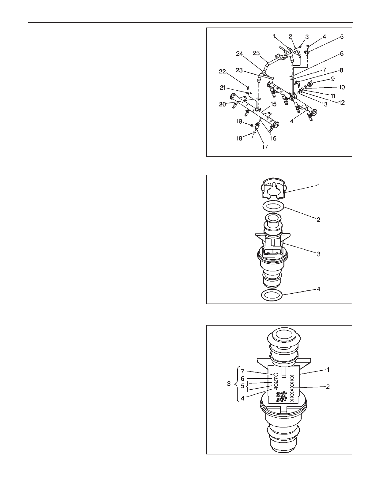
6.0L Fuel Metering System 3B - 15
Fuel Injector Replacement
Remove or Disconnect
Important: The engine oil may be contaminated with fuel
if the fuel injectors are leaking.
1. Remove the fuel rail assembly. Refer to Fuel Rail
Assembly Replacement.
2. Remove the injector retainer clip (4).
3. Insert the fork of J 43013, the fuel injector assembly
removal tool, between the fuel rail pod and the 3
protruding retaining clip ledges. Use a prying motion
while inserting the tool in order to force the injector
out of the fuel rail pod.
350543
4. Discard the injector retainer clip (1).
5. Remove the injector O-ring seals (2), (4) from both
ends of the injector. Discard the O-ring seals.
Install or Connect
Important: When ordering new fuel injectors, be sure
to order the correct injector for the application being
serviced.
The fuel injector assembly (1) is stamped with a part
number identifi cation (2). A four digit build date code (3)
indicates the month (4), day (5), year (6) and the shift (7)
that built the injector.
351185
351196
MEFI 4 - PCM
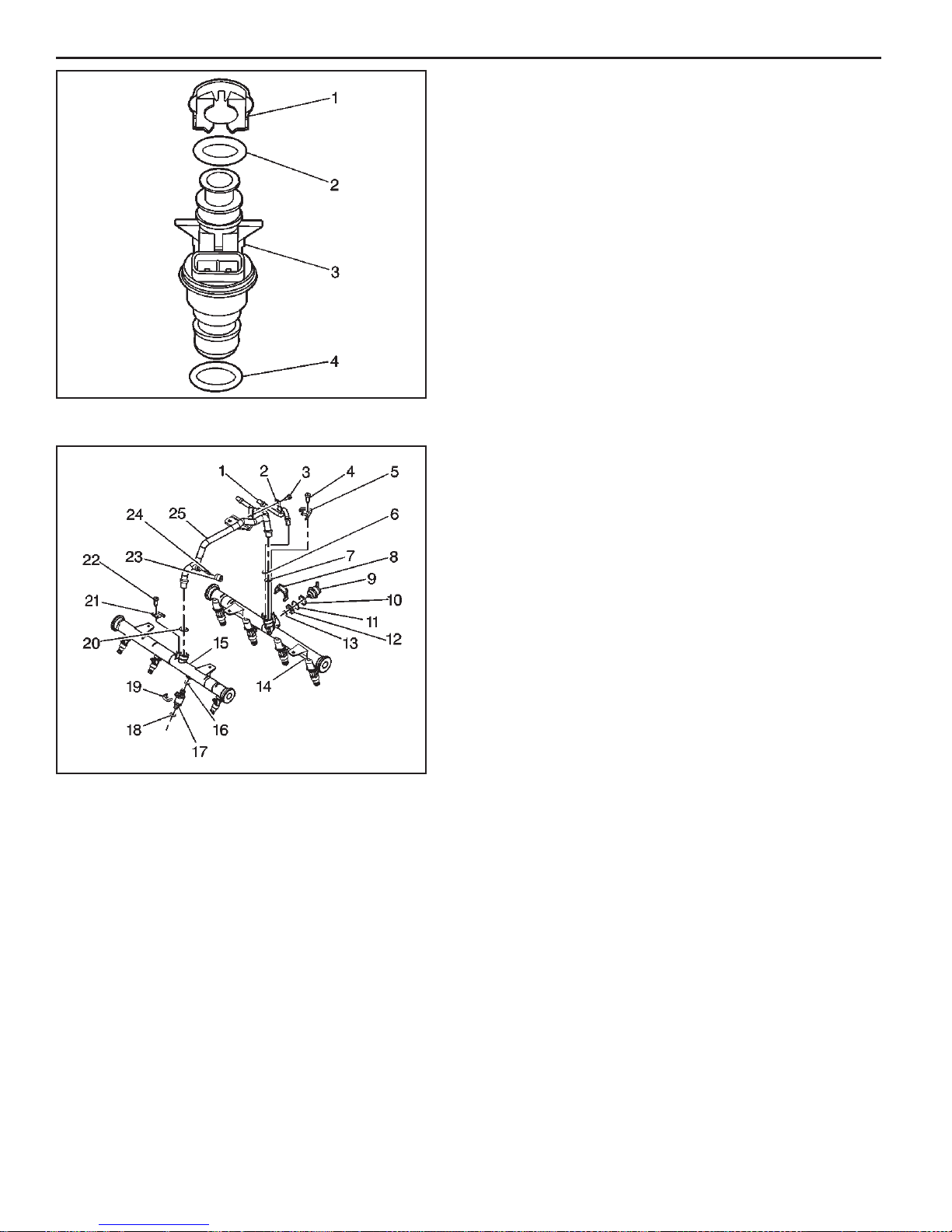
3B - 16 Fuel Metering System 6.0L
1. Lubricate the new O-ring seals (2), (4) with clean
engine oil.
2. Install the new injector O-ring seals on the injector.
3. Install a new retainer clip (1) on the injector.
351185
4. Push the fuel injector (5) into the fuel rail injector
socket with the electrical connector facing outwards.
The retainer clip (4) locks on to a fl ange on the fuel
rail injector socket.
5. Install the fuel rail assembly. Refer to Fuel Rail
Assembly Replacement procedure in this section.
MEFI 4 - PCM
350543

6.0L Fuel Metering System 3B - 17
Fuel Control Cell (FCC) Replacement - Screw
On Bowl and Clamp On Bowl
Important
Fuel pressure must be relieved before servicing the
•
fuel pump.
Refer to “Fuel Pressure Relief Procedure.”
•
Remove or Disconnect
1. Negative battery cable.
2. Fuel pump electrical connector.
3. Inlet and outlet fuel line fi ttings.
4. Fuel Control Cell (FCC) attaching bolts.
5. Fuel Control Cell (FCC).
Install or Connect
1. Fuel Control Cell (FCC).
2. Fuel Control Cell (FCC) attaching bolts.
3. Inlet and outlet fuel line fi ttings.
4. Fuel pump electrical connector.
5. Negative battery cable.
Inspect
Turn ignition switch to the “ON” position for 2 seconds,
•
then turn to the “OFF” position for 10 seconds. Turn
the ignition switch back to the “ON” position and check
for fuel leaks.
Fuel Control Cell (FCC) - Screw On Bowl
Fuel Control Cell (FCC) - Clamp On Bowl
MEFI 4 - PCM

3B - 18 Fuel Metering System 6.0L
Fuel Control Cell (FCC) - Screw On Bowl Drain Water (With Engine OFF)
1. Disconnect the two-wire electrical harness.
2. Hold the 3/4” jam nut located at the bottom of the FCC
bowl with a wrench, remove the 3/16” allen plug and
drain bowl contents into a suitable container.
Caution: Both fuel, which is explosive, and water will
drain from the FCC bowl.
3. Apply pipe sealant suitable for use with gasoline to the
threads fo the 3/16” allen plug.
4. Tighten the 3/16” allen plug while holding the 3/4” jam
nut with a wrench.
5. Re-connect the two-wire electrical harness.
Inspect
Turn ignition switch to the “ON” position for 2 seconds,
•
then turn to the “OFF” position for 10 seconds. Cycle
the ignition several times to fi ll the FCC bowl. Turn the
ignition switch back to the “ON” position and check
for fuel leaks.
FUEL
PRESSURE
REGULATOR
FUEL
PUMP
OR
"O"- RING
FUEL
FILTER
FUEL
PUMP
Fuel Control Cell (FCC) - Screw On Bowl Element Replacement (With Engine OFF)
1. Disconnect the two-wire electrical harness.
2. Hold the 3/4” jam nut located at the bottom of the FCC
bowl with a wrench, remove the 3/16” allen plug and
drain bowl contents into a suitable container.
Caution: Both fuel, which is explosive, and water will
drain from the FCC bowl.
3. Using a strap type oil fi lter wrench, remove the bowl
by turning it counterclockwise as viewed from the
bottom.
4. Slide bowl downward over the suspended fi lter element.
It may be necessary to pull the unit to one side or
remove the fuel line from the feed pump to remove
the bowl.
5. Remove the fuel fi lter element from the suspended
pump by gripping the fuel pump with one hand and
pulling the fi lter downward with the other hand.
6. Push on new fi lter element over the electric pump.
7. Using a pick made of soft material, such as a toothpick,
remove the old “O”-ring from inside the FCC bowl
mounting head.
Caution: The mounting head “O”-ring groove may
be damaged by using a sharp tool to remove this
“O”-ring.
8. Lubricate the new “O”-ring with a light grease and
install the new “O”-ring in the FCC head.
9. Grease taper and threads on the bowl and, by hand,
thread the bowl into the FCC mounting head. Tighten
the bowl fi rmly back into the head with an oil fi lter
wrench.
10. Apply pipe sealant suitable with gasoline to the 3/16”
allen plug.
11. Install and tighten the 3/16” allen plug while holding
the 3/4” jam nut with a wrench.
12. Re-connect the two-wire electrical harness.
FUEL
BOWL
FUEL
DRAIN
MEFI 4 - PCM
Inspect
Turn ignition switch to the “ON” position for 2 seconds,
•
then turn to the “OFF” position for 10 seconds. Cycle
the ignition several times to fi ll the FCC bowl. Turn the
ignition switch back to the “ON” position and check
for fuel leaks.

6.0L Fuel Metering System 3B - 19
Fuel Control Cell (FCC) - Clamp On Bowl Drain Water (With Engine OFF)
1. Disconnect the two-wire electrical harness.
2. Remove the 7/16” plug and drain the bowl contents
into a suitable container.
Caution: Both fuel, which is explosive, and water will
drain from the FCC bowl.
3. Apply pipe sealant, suitable for use with gasoline, to
the threads fo the 7/16” plug.
4. Install and tighten the 7/16” plug securely.
5. Reconnect the two-wire electrical harness.
Inspect
Turn ignition switch to the “ON” position for 2 seconds,
•
then turn to the “OFF” position for 10 seconds. Cycle
the ignition several times to fi ll the FCC bowl. Turn the
ignition switch back to the “ON” position and check
for fuel leaks.
6.0L 5.0/5.7L
OR
O-RINGS
FUEL
PRESSURE
REGULATOR
Fuel Control Cell (FCC) - Clamp On Bowl Element Replacement (With Engine OFF)
1. Disconnect the two-wire electrical harness.
2. Remove the 7/16” plug and drain the bowl contents
into a suitable container.
Caution: Both fuel, which is explosive, and water will
drain from the FCC bowl.
3. Remove the canister retaining clamp.
4. Slide bowl downward over the suspended fi lter element.
It may be necessary to pull the unit to one side to
remove the bowl.
5. Remove the fuel fi lter element from the suspended
pump by gripping the fuel pump with one hand and
pulling the fi lter downward with the other hand.
6. Push on new fi lter element over the electric pump.
7. Using a pick made of soft material, such as a toothpick,
remove the old “O”-rings from the FCC bowl mounting
head.
Caution: The mounting head “O”-ring grooves may
be damaged by using a sharp tool to remove these
“O”-rings.
8. Lubricate the new “O”-rings with fuel resistant “O”-ring
lubricant, and install the new “O”-rings on the FCC
head.
9. Apply pipe sealant, suitable for use with gasoline, to
the threads fo the 7/16” plug.
10. Install and tighten the 7/16” plug securely.
11. Install the bowl fi rmly back onto the FCC head.
12. Install the canister retaining clamp and tighten
securely.
13. Reconnect the two-wire electrical harness.
FUEL
PUMP
FUEL
FILTER
RETAINING
CLAMP
FUEL
BOWL
FUEL
DRAIN
Inspect
Turn ignition switch to the “ON” position for 2 seconds,
•
then turn to the “OFF” position for 10 seconds. Cycle
the ignition several times to fi ll the FCC bowl. Turn the
ignition switch back to the “ON” position and check
for fuel leaks.
MEFI 4 - PCM

3B - 20 Fuel Metering System 6.0L
Fuel Pressure Regulator Replacement
Remove or Disconnect
Important
Fuel pressure must be relieved before servicing the
•
fuel pump.
2
1
Refer to “Fuel Pressure Relief Procedure.”
•
1. Remove the FCC bowl. Refer to Fuel Control Cell Element Replacement steps 1-5.
2. Remove the two clamps (1).
3. Remove the fuel pressure regulator (2).
Install or Connect
4. Install the fuel pressure regulator (2).
5. Install two new clamps (1).
6. Push on a new fi lter element over the electric pump.
7. Install the FCC bowl. Refer to Fuel Control Cell Element Replacement steps 7-12.
Inspect
Turn ignition switch to the “ON” position for 2 seconds,
•
then turn to the “OFF” position for 10 seconds. Cycle
the ignition several times to fi ll the FCC bowl. Turn the
ignition switch back to the “ON” position and check
for fuel leaks.
MEFI 4 - PCM

6.0L Fuel Metering System 3B - 21
Low-Pressure Fuel Pump Replacement
Important
Fuel pressure must be relieved before servicing the
•
fuel pump.
Refer to “Fuel Pressure Relief Procedure.”
•
Remove or Disconnect
1. Negative battery cable.
2. Fuel pump electrical connector.
3. Inlet and outlet fuel line fi ttings.
4. Fuel pump attaching bolts.
5. Fuel pump.
Install or Connect
1. Fuel pump.
2. Fuel pump attaching bolts.
3. Inlet and outlet fuel line fi ttings.
4. Fuel pump electrical connector.
5. Negative battery cable.
Figure 3-3 - Low Pressure Fuel Pump
Inspect
Turn ignition switch to the “ON” position for 2 seconds,
•
then turn to the “OFF” position for 10 seconds. Turn
the ignition switch back to the “ON” position and check
for fuel leaks.
Fuel Pump Relay
Remove or Disconnect
1. Retainer, if installed.
2. Fuel pump relay electrical connector.
3. Fuel pump relay.
Important
The fuel pump relay is a electrical component. Do
•
Not soak in any liquid cleaner or solvent as damage
may result.
Install or Connect
1. Fuel pump relay.
2. Fuel pump relay electrical connector.
3. Retainer clip.
PS 16871
Figure 3-18- Fuel Pump Relay
MEFI 4 - PCM

3B - 22 Fuel Metering System 6.0L
Torque Specifi cations
Fastener Tightening Specifi cations
Application N•m Lb Ft Lb In
Throttle Body Attaching Screws 15 11
IAC Valve Attaching Screws 3.2 28
Fuel Pressure Connector 13 115
Fuel Rail Attaching Screws 10 89
MEFI 4 - PCM

8.1L Fuel Metering System 3C - 1
Marine Electronic Fuel Injection (MEFI)
Section 3C
Fuel Metering System - 8.1L
This section describes how the fuel metering system operates, and provides a description of components used on the
Marine Electronic Fuel Injection equipped engines. The fuel metering system information described in this section is
limited to the 8.1L. All other systems will be detailed in a separate section.
Contents
General Description .............................................Page 2
Purpose............................................................Page 2
Modes of Operation .........................................Page 2
Starting Mode............................................Page 2
Clear Flood Mode......................................Page 2
Run Mode..................................................Page 2
Acceleration Mode.....................................Page 2
Fuel Cutoff Mode.......................................Page 2
Power Reduction Mode.............................Page 2
Fuel Metering System Components ................Page 2
Quick-Connect Fittings.....................................Page 2
Fuel Supply Components (FCC System) .......Page 3
Fuel Pump Electrical Circuit ............................Page 4
Fuel Rail Assembly..........................................Page 4
Fuel Injectors.............................................Page 4
Pressure Regulator Assembly...................Page 5
Throttle Body Assembly...................................Page 5
Idle Air Control (IAC) Valve........................Page 6
Diagnosis ..............................................................Page 6
On-Board Service .................................................Page 6
Fuel Control On-Board Service .......................Page 7
Fuel Pressure Relief Procedure.......................Page 7
Flame Arrestor.................................................Page 7
Throttle Body Assembly...................................Page 8
Quick Connect Fitting(s) Service
(Metal Collar) ...................................................Page 9
Fuel Rail Assembly........................................Page 11
Fuel Pressure Regulator Assembly...............Page 16
Fuel Injectors .................................................Page 17
Fuel Control Cell (FCC).................................Page 20
Low-Pressure Fuel Pump ..............................Page 23
Fuel Pump Relay ...........................................Page 23
Torque Specifi cations ........................................Page 24
MEFI 4 - PCM

3C - 2 Fuel Metering System 8.1L
General Description
Purpose
The function of the fuel metering system is to deliver the
correct amount of fuel to the engine under all operating
conditions. Fuel is delivered to the engine by individual
fuel injectors mounted in the intake manifold near each
cylinder.
Modes Of Operation
The ECM looks at inputs from several sensors to determine
how much fuel to give the engine. The fuel is delivered under
one of several conditions , called “modes .” All the “modes” are
controlled by the ECM and are described below.
Starting Mode
When the ignition switch is turned to the crank position, the
ECM turns the fuel pump relay “ON,” and the fuel pump
builds up pressure. The ECM then checks the ECT, MAP
and TP sensors, and determines the proper air/fuel ratio
for starting. The ECM controls the amount of fuel delivered
in the starting mode by changing how long the injectors
are turned “ON” and “OFF.” This is done by “pulsing” the
injectors for very short times.
Clear Flood Mode
If the engine fl oods, it can be cleared by opening the throttle
to 100% (wide open throttle) during cranking. The ECM then
shuts down the fuel injectors so no fuel is delivered. The
ECM holds this injector rate as long as the throttle stays
at 100%, and the engine speed is below 300 RPM. If the
throttle position becomes less than 100%, the ECM returns
to the starting mode.
Run Mode
When the engine is fi rst started and RPM is above 300 RPM,
the system operates in the run mode. The ECM will calculate
the desired air/fuel ratio based on these ECM inputs: RPM,
ECT and MAP. Higher engine loads (MAP input) and colder
engine temperatures (ECT input) require more fuel, or a
richer air/fuel ratio.
Acceleration Mode
The ECM looks at rapid changes in TP sensor and MAP,
and provides extra fuel by increasing the injector pulse
width.
Fuel Cutoff Mode
No fuel is delivered by the injector when the ignition is “OFF,”
to prevent dieseling. Also, injector pulses are not delivered if
the ECM does not receive distributor reference pulses , which
means the engine is not running. The fuel cutoff mode is also
enabled at high engine RPM, as an overspeed protection for
the engine. When fuel cutoff is in effect due to high RPM,
injector pulses will resume after engine RPM drops below the
maximum OEM RPM specifi cation (Rev Limit).
Power Reduction Mode
Pow er reduction mode is a function of the ECM that reduces
engine power under certain conditions. Power reduction will
disable one fuel injector driver when the engine speed goes
above 2500 rpm, and enable the fuel injector driver when
the engine speed drops below 1200 rpm. Power reduction
may be active for the following conditions:
• Engine coolant temperature too high
• Low oil pressure
• Transmission temperature too high (if applicable)
Fuel Metering System Components
The fuel metering system (Figure 3-1) is made up of the
following parts:
Fuel supply components (fuel tank, pump, lines, fi lter).
•
Fuel pump electrical circuit.
•
Fuel rail assembly, including fuel injectors and pressure
•
regulator assembly.
Throttle body assembly, including an IAC valve and
•
TP sensor.
Quick-Connect Fittings
Quick-Connect fi ttings provide a simplifi ed means of
installing and connecting fuel system components. The
fi ttings consists of a unique female connector and a
compatible male pipe end. O-rings, located inside the
female connector, provide the fuel seal. Integral locking
tabs inside the female connector hold the fi ttings together.
Fuel Supply Components (FCC System)
The Fuel Control Cell (FCC) incorporates two (2) fuel
pumps to provide uninterrupted fl ow of fuel to your marine
engine.
Fuel is fed into the FCC by a low-pressure, high volume
electric fuel pump. This pump fl ows fuel at a volume which
exceeds the fuel fl ow rate required of the high-pressure
pump by engine demands.
The high pressure pump, mounted inside the FCC bowl,
provides the necessary fuel pressure and volume to maintain
proper engine performance, and always has an ample
supply of fuel to meet the idle, cruise and acceleration fuel
requirements of the engine.
The fuel pressure regulator, located on the fuel rail, controls
fuel pressure and maintains a constant pressure across the
fuel delivery system. Fuel not used by the engine, excess
fuel, is returned to the FCC canister.
The fuel delivered to the engine by the FCC is fi ltered by a
fi lter and water separator element, which surrounds the high
pressure pump inside the FCC bowl.
The fuel enters the FCC bowl from two (2) components,
the low-pressure pump (initial input) and the fuel pressure
regulator (unused recirculating). Fuel exits the FCC bowl at
two (2) locations, the high-pressure output to the fuel rail
and all excess fuel in the FCC bowl is routed back to the
fuel tank via a return line.
MEFI 4 - PCM

8.1L Fuel Metering System 3C - 3
PRESSURE
REGULATOR
FUEL RAIL ASSEMBLY
ENGINE
FUEL
CONTROL
CELL
Fuel Control Cell Fuel System
LOW-
PRESSURE
FUEL
PUMP
FUEL
FILTER
FUEL
TANK
Figure 3-1 - Fuel Metering System (Typical)
Figure 3-2 - Fuel Control Cell (FCC)
Figure 3-3 - Low Pressure Fuel Pump
MEFI 4 - PCM

3C - 4 Fuel Metering System 8.1L
Fuel Pump Electrical Circuit
When the ignition switch is turned “ON,” the ECM turns
the fuel pump relay “ON” for two seconds causing the fuel
pump(s) to pressurize the MEFI fuel system.
When the ignition switch is turned to the crank position,
the ECM turns the fuel pump relay “ON” causing the fuel
pump to run.
If the ECM does not receive ignition reference pulses
(engine cranking or running), it shuts “OFF” the fuel pump
relay, causing the fuel pump to stop.
An inoperative fuel pump relay will result in an “Engine
Cranks But Will Not Run” condition.
Fuel Rail Assembly
The fuel rail (Figure 3-3) is mounted to the engine intake
manifold, and performs several functions. It positions the
injectors (3) in the intake manifold, distributes fuel evenly
to the injectors, and integrates the fuel pressure regulator
(2) into the fuel metering system.
Fuel Injectors
The Multec 2 fuel injector assembly is a solenoid
operated device, controlled by the ECM, that meters
pressurized fuel to a single engine cylinder. The ECM
energizes the high-impedance (12.2 ohms) injector
solenoid (1) to open a normally closed ball valve (2).
This allows fuel to fl ow into the top of the injector,
past the ball valve and through a director plate (3) at
the injector outlet. The director plate has four machined
holes that control the fuel fl ow, generating a spray of
fi nely atomized fuel at the injector tip. Fuel from the
injector tip is directed at the intake valve, causing it to
become further atomized and vaporized before entering
the combustion chamber. An injector stuck partly open
can cause a loss of pressure after engine shutdown.
Consequently, long engine cranking times would be
noticed on some engines.
Figure 3-3 - Fuel Rail Assembly
MEFI 4 - PCM
341661
351198
Figure 3-4 - Fuel Injector Assembly

8.1L Fuel Metering System 3C - 5
Pressure Regulator Assembly
The pressure regulator is a diaphragm-operated relief
valve with fuel pump pressure on one side, and regulator
spring pressure and intake manifold vacuum on the other
side (Figure 3-5). The regulator’s function is to maintain
a constant pressure differential across the injectors at all
times. The pressure regulator compensates for engine load
by increasing fuel pressure as engine vacuum drops.
With the ignition “ON,” engine “OFF” (zero vacuum),
fuel pressure at the pressure test connection should be
284-325 kPa (41-47 psi). If the pressure is too low, poor
performance or a “no-start” may result. If pressure is too
high, excessive odor may result.
Throttle Body Assembly
The throttle body assembly is attached to the intake
manifold air plenum, and is used to control air fl ow into the
engine, thereby controlling engine output (Figure 3-6). The
throttle plates within the throttle body are opened by the
driver through the throttle controls. During engine idle, the
throttle plates are closed, and air fl ow control is handled by
the Idle Air Control (IAC) valve, described below.
The throttle body also provides the location for mounting
the TP sensor and for sensing changes in engine vacuum
due to throttle plates position.
Figure 3-5 - Pressure Regulator Assembly
69059
mefi 4335
Figure 3-6 - Throttle Body Assembly
MEFI 4 - PCM

3C - 6 Fuel Metering System 8.1L
Idle Air Control (IAC) Valve
The purpose of the IAC valve assembly (Figures 3-7 and
3-8) is to control engine idle speed, while preventing stalls
due to changes in engine load.
The IAC valve, mounted to the throttle body, controls
bypass air around the throttle plates (Figure 3-7). By
moving a conical valve known as a pintle, IN, towards the
seat (to decrease air fl ow); or OUT, away from the seat (to
increase air fl ow), a controlled amount of air moves around
the throttle plates. If RPM is too low, more air is bypassed
around the throttle plates to increase it. If RPM is too
high, less air is bypassed around the throttle plates to
decrease it.
The ECM moves the IAC valve in small steps. These can
be monitored by scan tool test equipment, which plugs into
the Data Link Connector (DLC).
During idle, the proper position of the IAC valve is calculated
by the ECM, based on battery voltage, coolant temperature
and engine RPM. If the RPM drops below specifi cation
and the throttle plates are closed, the ECM senses a
near stall condition and calculates a new valve position
to prevent stalling.
Engine idle speed is a function of total air fl ow into
•
the engine based on IAC valve pintle position plus
throttle plates opening.
1
2
“Controlled” idle speed is programmed into the ECM,
•
which determines the correct IAC valve pintle position
to maintain the desired idle speed for all engine
operating conditions and loads.
The minimum air rate is set at the factory with a stop
•
screw . This setting allows enough air fl ow by the throttle
plates to cause the IAC valve pintle to be positioned
at a calibrated number of steps (counts) from the seat,
during “controlled” idle operation. This minimum air
rate setting should not be altered by turning the stop
screw or bending the linkage. Improper idle control
will result.
➤
➤
A
➤
B
➤
1 O-RING - IAC VALVE
2 IAC VALVE ATTACHING SCREW
A DISTANCE OF PINTLE EXTENSION
B DIAMETER OF PINTLE
Figure 3-8 - Flange Mounted Type IAC Valve
1
2
8-24-94
RS 22181
A
4
B
1 IDLE AIR CONTROL (IAC) VALVE
2 THROTTLE BODY ASSEMBLY
3 THROTTLE VALVE
4 IAC VALVE PINTLE
A ELECTRICAL INPUT SIGNAL
B AIR INLET
Figure 3-7 - IAC Valve Air Flow Diagram
3
8-25-94
RS 22193
Diagnosis
If the Engine Cranks But Will Not Run or immediately
stalls, Table A-3 of the Diagnosis section must be used
to determine if the failure is in the ignition system or the
fuel system.
On-Board Service
Caution:
To reduce the risk of fi re and personal injury, relieve
fuel system pressure before servicing fuel system
components.
After relieving fuel pressure, a small amount of fuel may
be released when servicing fuel lines or connections.
To reduce the chance of personal injury, cover fuel
line fi ttings with a shop towel before disconnecting
to catch any fuel that may leak out. Place the towel
in an approved container when disconnection is
completed.
MEFI 4 - PCM

8.1L Fuel Metering System 3C - 7
Fuel Control On-Board Service
The following is general inf ormation required when working
on the fuel system:
Always keep a dry chemical fire extinguisher near
•
the work area.
Fuel pipe fittings require new O-rings when
•
assembling.
Do not replace fuel pipe with fuel hose.
•
Always bleed off fuel pressure before servicing any
•
fuel system components.
Do not do any repairs on the fuel system until you
•
have read the instructions and checked the fi gures
relating the repair.
Observe all notices and cautions.
•
Fuel Pressure Relief Procedure
Tool Required:
J 34730-1, Fuel Pressure Gauge
Important
• Refer to manufacturer’s warnings and cautions before
proceeding.
1. Disconnect negative battery cable to avoid possible
fuel discharge if an accidental attempt is made to
start the engine.
2. Loosen fuel filler cap to relieve any tank vapor
pressure.
3. Connect fuel pressure gauge J 34730-1 to fuel pressure
connector assembly. Wrap a shop towel around fi tting
while connecting the gauge to avoid any spillage.
4. Install bleed hose into an approved container and open
valve to bleed system pressure. Fuel connections are
now safe for servicing.
5. Drain any fuel remaining in the gauge into an approved
container.
Flame Arrestor
Remove or Disconnect
1. Flame arrestor retaining clamp.
2. Flame arrestor.
Inspect
• Flame arrestor element for dust, dirt or water. Replace
if required.
Install or Connect
1. Flame arrestor to throttle body.
2. Flame arrestor retaining clamp to fl ame arrestor.
MEFI 4 - PCM

3C - 8 Fuel Metering System 8.1L
Throttle Body Assembly Replacement
Remove or Disconnect
1. Disconnect the negative battery cable.
2. Remove the fl ame arrestor clamp and fl ame arrestor.
3. Disconnect the electrical connectors from the IAC
valve and the TP sensor.
4. Disconnect the throttle cable.
5. Remove the throttle body assembly attaching nuts.
6. Remove the throttle body assembly and gasket.
7. Discard the gasket.
Important: To o prevent damage to the throttle valve, it
is essential that the unit be placed on a holding fi xture
before performing service.
Notice: Stuff a rag in the intake manif old opening to prevent
foreign material from entering the engine.
Inspect
• Manifold bore for loose parts and foreign material.
• Manifold mating surface for cleanliness or burrs that
could affect gasket sealing.
Important: Clean the throttle bore and valve deposits
using carburetor cleaner and a parts cleaning brush. Do
Not use a cleaner that contains methyl ethyl ketone, an
extremely strong solvent, and not necessary for this type
of deposit.
The throttle body metal parts may be cleaned in a cold,
immersion type cleaner following the disassembly of the
unit.
Notice: The TP sensor and IAC valve should not come in
contact with solvent or cleaner, as they may be damaged.
These components must be removed before immersion.
Follow the procedures outlined in this section.
Caution: Safety glasses must be worn when using
compressed air, as flying dirt particles may cause
eye injury.
• Clean all metal parts thoroughly and blow dry with
compressed air. Be sure that all fuel and air passages
are free of dirt and burrs.
• Inspect the mating surfaces for damage that could
affect gasket sealing.
• Inspect throttle body for cracks in casting.
• The thread-locking compound supplied in the service
repair kit is a small vial of thread-locking compound
with directions for use. If this material is not available,
use Loctite® 262 or equivalent.
Notice: When precoating the mounting bolts, do not use
a higher strength locking compound than recommended.
This may cause the removal of the bolts to be very
diffi cult.
Throttle Body Assembly
Throttle Body Removal
MEFI 4 - PCM
Install or Connect
1. Install a new throttle body gasket.
2. Install the throttle body assembly and the throttle body
assembly attaching nuts.
Tighten
Tighten the throttle body assembly attaching nuts to
10 N.m (89 lb in).
3. Reconnect the throttle cable.
4. Reconnect the electrical connectors to the IAC valve
and the TP sensor.
5. Install the fl ame arrestor and clamp. Securely tighten
the clamp.
6. Reconnect the negative battery cable.

8.1L Fuel Metering System 3C - 9
Quick Connect Fitting(s) Service
Tools Required
J 37088-A Tool Set, Fuel Line Quick-Connect Separator
J 44581 Fuel Line Quick Connect Separator
Remove or Disconnect
1. Relieve the fuel system pressure before servicing
any fuel system connection. Refer to Fuel Pressure
Relief Procedure.
2. Remove the retainer from the quick-connect fi tting.
Caution: Wear safety glasses in order to avoid eye
damage.
3. Blow dirt out of the fi tting using compressed air.
12776
4. Choose the correct tool from the tool set for the size of
the fi tting. Insert the tool into the female connector, then
push inward in order to release the locking tabs.
5. Pull the connection apart.
6. Use a clean shop towel in order to wipe off the male
pipe end.
7. Inspect both ends of the fi tting for dirt and burrs. Clean
or replace the components as required.
12780
12782
MEFI 4 - PCM

3C - 10 Fuel Metering System 8.1L
Install or Connect
1. Apply a few drops of clean engine oil to the male
pipe end.
12784
2. Push both sides of the fi tting together in order to snap
the retaining tabs into place.
MEFI 4 - PCM
12786
3. Once installed, pull on both sides of the fi tting in order
to make sure the connection is secure.
4. Install the retainer to the quick-connect fi tting.
12787

8.1L Fuel Metering System 3C - 11
Fuel Rail Assembly Replacement
Remove or Disconnect
1. Relieve the fuel system pressure. Refer to Fuel
Pressure Relief Procedure.
2. Before removal, clean the fuel rail assembly with a
spray type engine cleaner, GM X-30A or equivalent,
if necessary. Follow the package instructions. Do not
soak fuel rails in liquid cleaning solvent.
3. Remove the engine cover.
665445
4. Disconnect the TP sensor harness connector.
5. Disconnect the IAC valve harness connector.
6. Identify the connectors to their corresponding
injectors to ensure correct injector fi ring order after
reassembly.
7. Pull the top portion (2) of the injector connector up. Do
not pull the top portion of the connector past the top
of the white portion (1).
372749
MEFI 4 - PCM
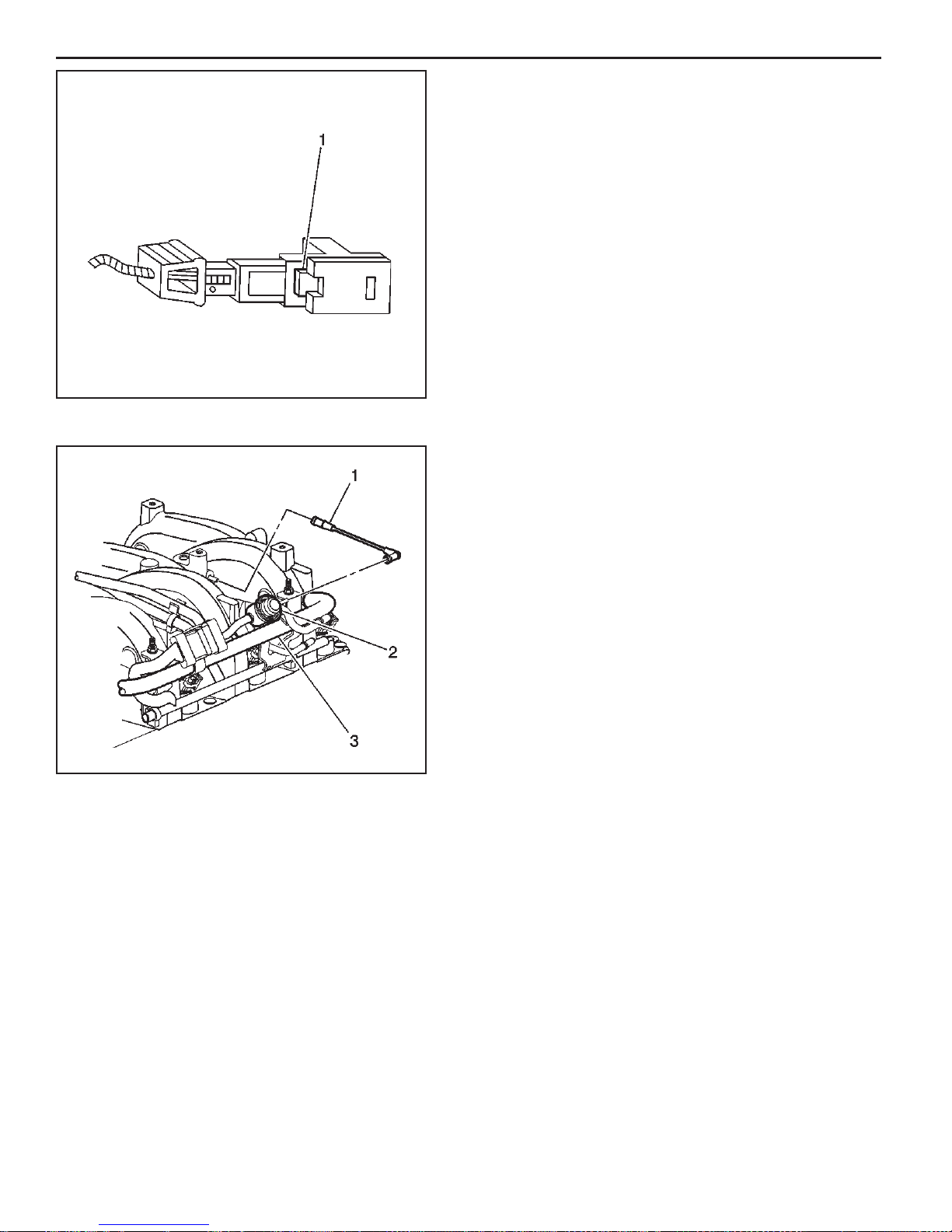
3C - 12 Fuel Metering System 8.1L
8. Push the tab (1) on the lower side of the injector
connector in order to release the connector from
the injector.
9. Repeat step 9 and step 10 for each injector
connector.
372753
10. Disconnect the fuel feed and return from the fuel
rail. Refer to Quick Connect Fitting procedure in this
section.
11. Disconnect the fuel pressure regulator vacuum line.
MEFI 4 - PCM
665447

8.1L Fuel Metering System 3C - 13
12. Remove the fuel rail attaching bolts.
13. Remove the fuel rail assembly.
665443
14. Remove the injector lower O-ring seal (4) from the
spray tip end of each injector (3).
15. Discard the O-ring seals.
Install or Connect
1. Lubricate the new lower injector O-ring seals (4) with
clean engine oil.
2. Install the new O-ring seals (4) on the spray tip end
of each injector (3).
351185
351185
MEFI 4 - PCM

3C - 14 Fuel Metering System 8.1L
3. Install the fuel rail assembly to the intake manifold.
4. Apply a 5 mm (0.020 in) band of GM P/N 12345382
threadlock or equivalent to the threads of the fuel rail
attaching bolts.
5. Install the fuel rail attaching bolts.
Tighten
Tighten the fuel rail attaching bolts to 12 N.m (106
lb in).
665443
6. Connect the fuel pressure regulator vacuum line.
7. Connect the fuel feed and return lines to the fuel
rail. Refer to Quick Connect Fitting procedure in this
section.
MEFI 4 - PCM
665447

8.1L Fuel Metering System 3C - 15
8. Connect the injector electrical connectors
• Install each connector on the proper injector in
order to ensure correct injector fi ring order.
• Rotate the injectors as required in order to avoid
stretching the wire harness.
mefi 4338
9. Reconnect the TP sensor harness connector.
10. Reconnect the IAC valve harness connector.
11. Install the engine cover.
12. Connect the negative battery cable.
13. Inspect for leaks.
13.1. Turn the ignition ON for 2 seconds.
13.2. Turn the ignition OFF for 10 seconds.
13.3. Turn the ignition ON.
13.4. Inspect for fuel leaks.
665445
MEFI 4 - PCM

3C - 16 Fuel Metering System 8.1L
Fuel Pressure Regulator Replacement
Remove or Disconnect
1. Relieve the fuel system pressure. Refer to Fuel
Pressure Relief Procedure.
2. Disconnect the fuel pressure regulator vacuum line
(1).
665447
3. Clean any dirt from the fuel pressure regulator retainer
and the surrounding area.
4. Remove the fuel pressure regulator retainer (9).
5. Remove the fuel pressure regulator (8) from the fuel
pressure regulator housing.
MEFI 4 - PCM
705539
Install or Connect
1. Install the backup ring (10) on the fuel pressure
regulator (8).
2. Install the new large O-ring (11) on the fuel pressure
regulator.
3. Install the regulator fi lter (12) on the fuel pressure
regulator.
4. Install the new small O-ring (13) on the fuel pressure
regulator.
5. Lubricate the fuel pressure regulator large O-ring and
the small O-ring with clean engine oil.
6. Push the fuel pressure regulator into the regulator
housing on the fuel rail.
7. Install a new fuel pressure regulator retainer (9).
705539

8.1L Fuel Metering System 3C - 17
8. Connect the fuel pressure regulator vacuum line.
9. Connect the negative battery cable.
10. Inspect for leaks.
10.1. Turn the ignition ON for 2 seconds.
10.2. Turn the ignition OFF for 10 seconds.
10.3. Turn the ignition ON.
10.4. Inspect for fuel leaks.
665447
Fuel Injector Replacement
Remove or Disconnect
Important: The engine oil may be contaminated with fuel
if the fuel injectors are leaking.
1. Remove the fuel rail assembly. Refer to Fuel Rail
Assembly Replacement.
2. Remove the injector retainer clip (4).
3. Insert the fork of J 43013, the fuel injector assembly
removal tool, between the fuel rail pod and the 3
protruding retaining clip ledges. Use a prying motion
while inserting the tool in order to force the injector
out of the fuel rail pod.
705539
MEFI 4 - PCM

3C - 18 Fuel Metering System 8.1L
4. Discard the injector retainer clip (1).
5. Remove the injector O-ring seals (2), (4) from both
ends of the injector. Discard the O-ring seals.
351185
Install or Connect
Important: When ordering new fuel injectors, be sure
to order the correct injector for the application being
serviced.
The fuel injector assembly (1) is stamped with a part
number identifi cation (2). A four digit build date code (3)
indicates the month (4), day (5), year (6) and the shift (7)
that built the injector.
MEFI 4 - PCM
351196
1. Lubricate the new O-ring seals (2), (4) with clean
engine oil.
2. Install the new injector O-ring seals on the injector.
3. Install a new retainer clip (1) on the injector.
351185
 Loading...