

Page 1
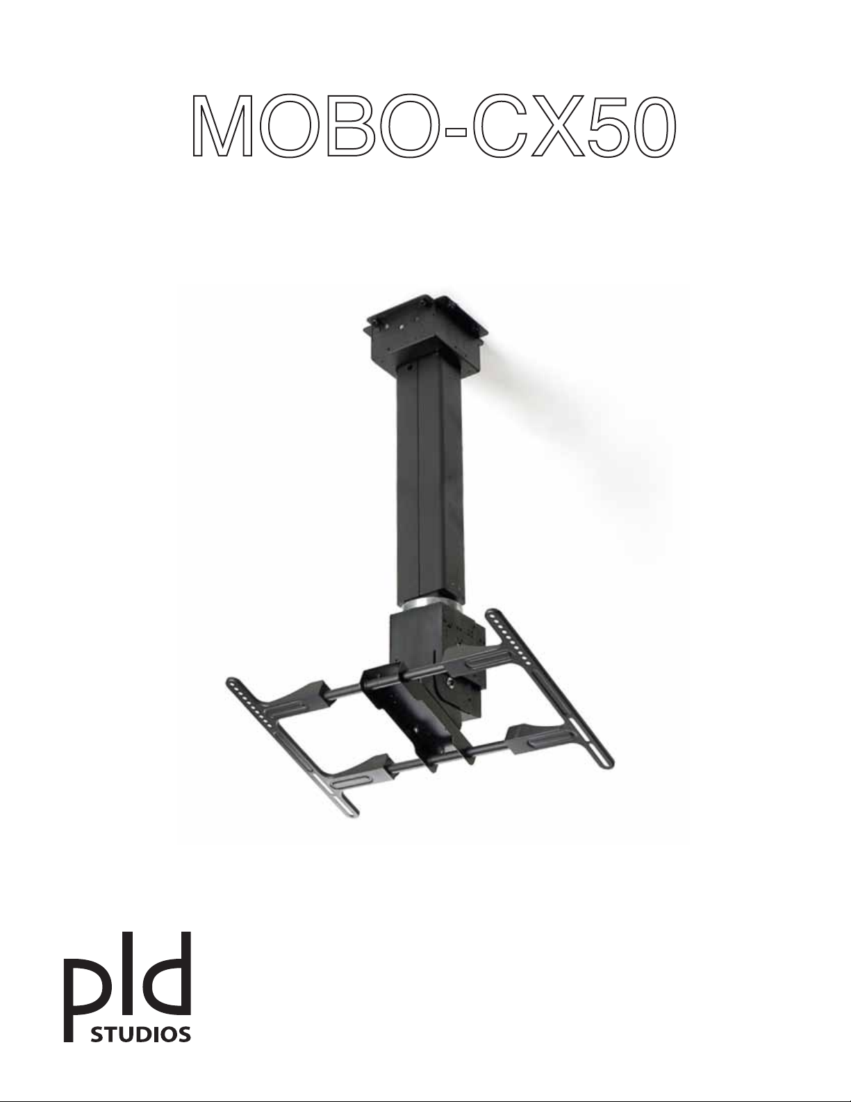
Motorized Flat Screen TV Ceiling Mount
PLD STUDIOS LLC Tel/Fax: 415.992.6620 [email protected] www.pldstudios.com
Page 2
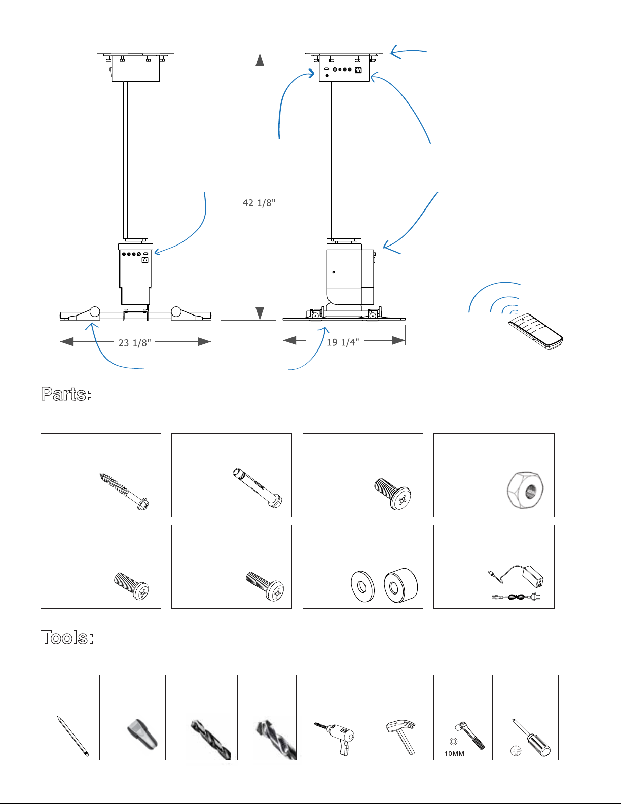
“Interface Ports”
(the good stuff goes in here...
...and comes out here.)
“Ceiling Plate”
“The Motors”
Your TV goes here!
Please make sure you have all parts before beginning installation. If any parts are missing or damaged, contact your
retailer and DO NOT ATTEMPT INSTALLATION. Use only parts provided by the manufacturer or damage may result.
②①
Wood screws
9 pcs
⑤
M6 x 15mm
Television screw
4 pcs
The following tools are necessary for proper installation. If you don't own them already, you could borrow them from
your neighbor. But if your neighbor is like ours, it's better to just go buy them.
Concrete anchoring bolt
9 pcs
⑥
M5 x 15mm
Television screw
4 pcs
③
M6 x 15mm
Bracket bolt
4 pcs
⑦
Washer and Spacer
4 pcs each
(batteries included!)
④
M6
Bracket nut
4 pcs
⑧
Power adapter
1 pc
“Remote Control”
pencil
stud-finder
3/16”
drill bit
13/32”
masonry
drill bit
power drill hammer socket
wrench
Phillips
screw driver
Page 3

The television and bracket are heavy and must be attached securely to a wall or ceiling that is strong enough
to support them both. Attaching to drywall is not advised. If you are not familiar with how your walls or ceilings are
constructed, you should seek the advice of an expert. The manufacturer and retailer DO NOT assume any
liability for improper installations or misuse. So if your television falls off the wall, it is entirely your own problem.
DANGER!
This motorized bracket is an electrical device. This unit is designed for indoor use only. You should only use
it in a dry and clean environment, and plugged into a properly grounded electrical outlet. If you die of electrocution,
you will not be able to enjoy your television.
To reduce the risk of electrical shock you should take some basic precautions, including:
1. Always unplug the unit when installing, removing, mounting, adjusting, or cleaning the unit.
2. Never operate the unit outside of the limits, specifications or parameters described in this booklet.
3. Do not attach anything else to the bracket other than a television of the specified size/weight.
4. Do not attach any other accessories or devices, and do not let anyone touch the unit while in operation.
5. Never operate the system if it has become wet; if it shows any signs of damage; if it has become clogged
with dust, lint or hair; shows signs of excessive wear and tear; or, if the power cords have become
damaged or frayed.
6. Keep the unit and power cords away from heat sources such as vents, heaters, fireplaces, or radiators.
7. Use only a dry cloth to clean the unit; do not use any chemicals, sprays or liquids of any kind.
8. Periodically check to make sure all screws and fastening devices are properly tightened and secure.
To avoid damage to the screw threads be sure not to over-tighten.
This unit is designed for PROFESSIONAL INSTALLATION.
If you attempt installation yourself, you assume all risks
and consequences, so please be sure that you know what
you’re doing. If your spouse says, “Don’t worry, I know what
I’m doing,” you should probably still worry. Incorrect installation
can result in personal injury, and damage to your television or
other property.
The manufacturer and retailer are NOT responsible for improper
installations.
The limited warranty only covers defects in the design or
manufacture of the bracket, and doesn’t cover issues arising
from improper installation or misuse. If you are uncertain about
how to safely install this unit, please seek help from a professional
installer. These instructions are based upon a typical installation
scenario; your particular circumstances may require special
arrangements that are outside the scope of these instructions and
should be undertaken only by a trained professional.
WARNING!!!
Page 4

We strongly recommend that this unit be installed
only in consultation with a professional installer.
WARNING: Do NOT attempt to operate the unit until it has been
installed in a fully vertical position; plugging in the unit before full
installation will damage the unit and void your warranty.
Step 1. Determine Ceiling Type (Wood or Concrete)
Before you begin, you must
make sure your chosen installation
location can support the weight of both
the bracket and the television.
Typically this will require you to screw
directly into wood joists/braces
or into a solid masonry ceiling surface.
If you are uncertain whether your desired
location can support the weight, consult an
expert before attempting.
A
B
Step 2. (A) Mount Ceiling Plate - Wood
The support beams should have sufficient supoorts already installed.
Consult a professional contractor to determine proper positioning
and alignment.
Remove the ceiling plate from the upper motor housing and use
it to mark the location of the screw holes. Use a power drill with a
3/16” bit to drill starter holes in the studs. Mount the ceiling plate
to the studs using the eight wood screws (discard the plastic
screw sleeves if any).
Step 2. (B) Mount Ceiling Plate - Concrete
Ensure the ceiling thickness is at least 3 ¼ inches and that there
are no materials such as rebar or steel plates, etc., in the mounting
location.
Loosen the ceiling plate from the upper motor housing and use it
to mark the location of the screw holes. Use a power drill with a
13/32” masonry bit and drill the holes in the marked locations to a
depth of approx 2 3/4 inches. Mount ceiling plate using the eight
concrete anchoring bolts.
Page 5
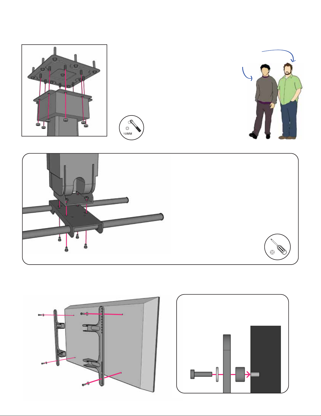
Step 3. Join Motor Housing to Ceiling Plate (2 people required)
CAUTION!
At least two people are required
to safely lift the ceiling mount!
Unscrew the eight nuts from ceiling plate mounting
bolts and attach the motor housing to the ceiling plate
using a 3/16” socket wrench. To avoid stripping, do not
tighten the nuts completely until all the nuts have been
at least installed and lightly tightened.
Step 4. Attach Bracket Rail Assembly
The bracket rails are installed in the factory but
may need to be adjusted to ensure the rails are
centered by loosening the locking screws. Install
the entire bracket to the lower motor housing
using 4 bracket screws (③) and 4 nuts (④).
Step 5. Attach Bracket Arms to Television
Locate and align the TV mounting holes
with the bracket. Use the television screws
(⑤or ⑥) along with the washers and
spacers (⑦) and tighten gently.
TV
Page 6
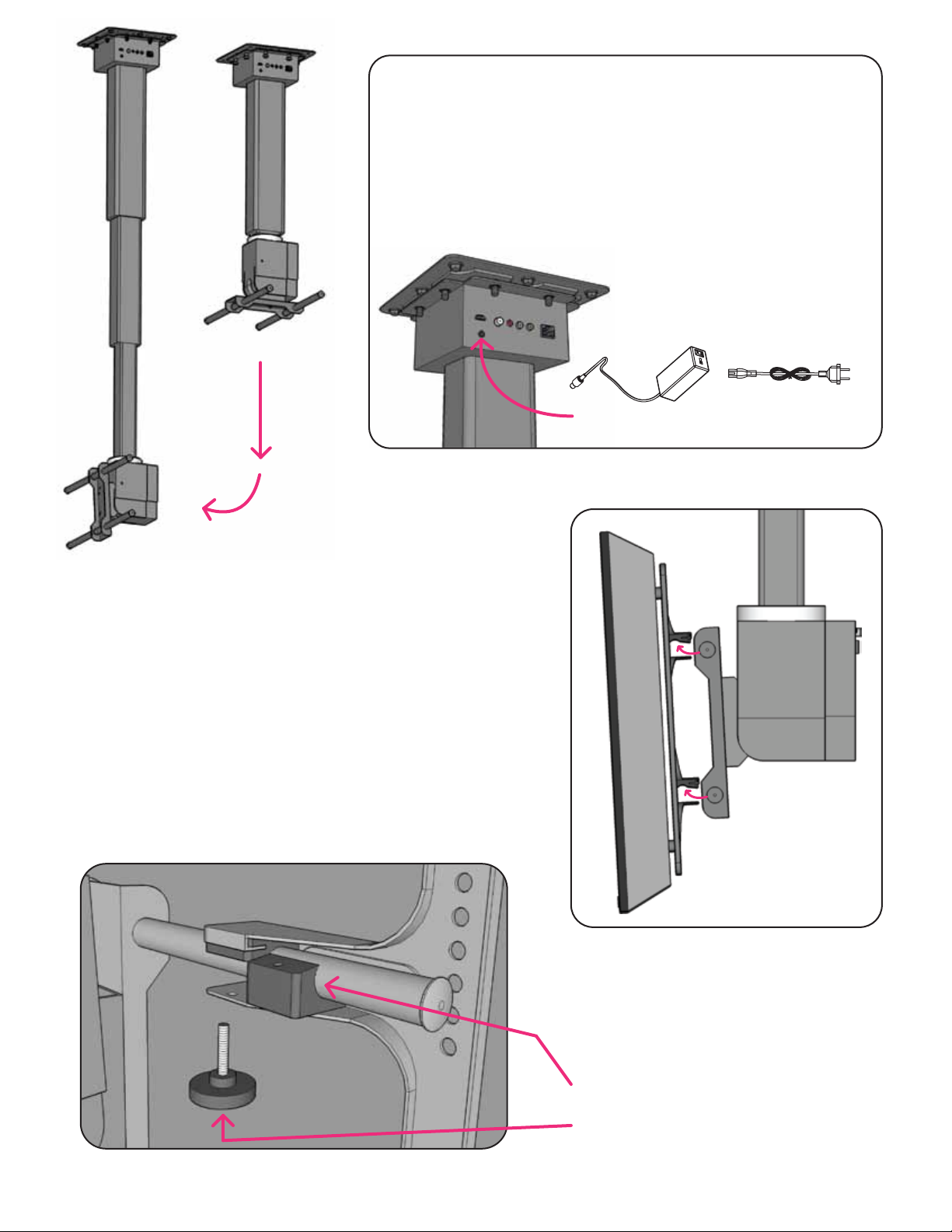
Step 6. Attach power cord and AV cables to upper housing
Now it is safe to test the function of the mounting arm. Use the
remote (see Operating Instructions) to lower mount to its fully
extended position and to ensure the rail bracket is in its
vertical position.
PLUG POWER IN HERE!
CAUTION!
Never attempt to manually extend or retract
the arm. Attempting to do so will damage the
unit and void the warranty.
Step 7. Place Television on Rails (2 people required)
First remove the locking blocks and hand screws if in place.
Carefully place the television on rails and check to make sure
it is properly seated in the bracket channels. Someone must
brace the television until the locking blocks are secure.
Step 8. Secure Locking Blocks and Handscrews
CAUTION!
All four locking blocks must be
properly installed before
attempting operation.
Slide the Locking Blocks into place.
Tighten the Locking Handscrews.
Page 7
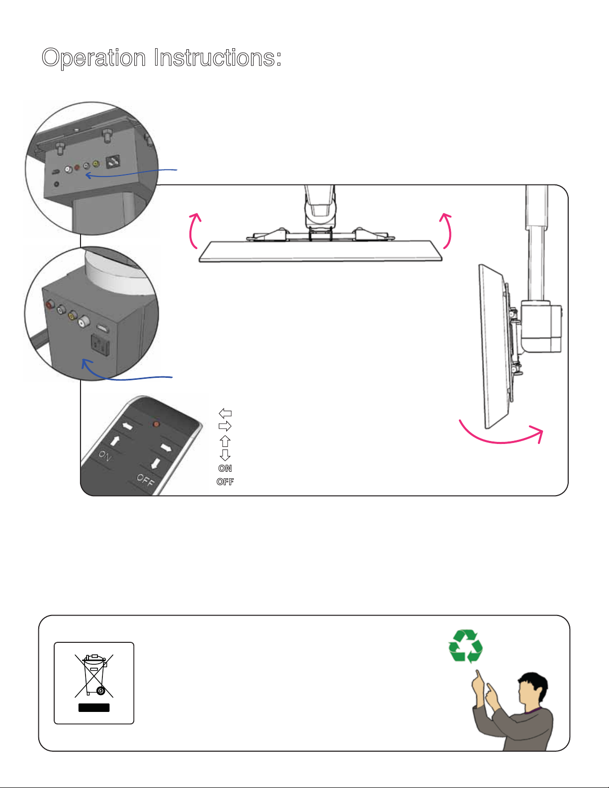
Step 9. Attach AV and Power
Attach AV and power cables from your sources to the interface ports at the top
of the unit. DO NOT ATTACH source cables directly to the TV; ONLY attach the TV
inputs to the interface ports at the bottom of the extension arm. Make sure to use
short cables to avoid snagging.
from AV sources
35˚ 35˚
Step 10. Remote Control
Install battery (included) and test operation of the mount.
Left/right rotation: 35° in each direction (from vertical center)
Tilt: 0° to 87° (from horizontal)
Extension: 40” (1000mm) (from retracted position)
to television
: hold down and turns the TV clockwise
: hold down and turns the TV counter-clockwise
: hold down and tilts the TV up
: hold down and tilts the TV down
: one click to fully extend the ceiling mount and tilt TV to vertical
: one click to fully retract the ceiling mount and tilt TV to horizontal
87˚
CAUTION!
Please ensure that the area around the television is free from any obstructions that
might prevent free movement of the unit, otherwise you may damage the television or motor.
Also make sure that your AV and power cabling are installed so that movement of the
television does not cause snagging or damage to your cables or connectors.
This device contains electronics and other materials
which should only be disposed of in a proper disposal
facility designed to process electronic waste.
Please help protect our environment:
DO NOT dispose of this unit in household or office trash.
Page 8

General Specs:
Product Dimensions (inch)
Carton Dimension (inch) Net Weight (lbs.) Gross Weight (lbs.)
Electrical Specs:
Rated Voltage
DC24V
Current (no load) Current (rated load) Operation Temperature Maximum Humidity
0.5A 2A -20˚C to 50˚C 80% RH
Operational Specs:
TV Size
Maximum
Install Pattern
32” - 65” 860 x 460(mm) 185 x 135 (mm) 110 lbs. ±35°
Minimum
Install Pattern
Maximum
Bearing Weight
Swivel Angle
Tilt Angle
Down: 87°
Certifications:
Pending
This device complies with part 15 of the FCC Rules. Operation is subject to the following two conditions: (1) this device may not cause harmful
interference, and (2) this device must accept any interference received, including interference that may cause undesired operation.
Approved
Approved Approved
ONE YEAR LIMITED WARRANTY
PLD STUDIOS LLC (hereinafter, "PLD") warrants to original end-users of PLD products that those products will be free from defects in
materials and workmanship, under normal use, for a period of one year from the date of purchase by the original end-user. At its option,
PLD will repair or replace, or refund the purchase price of, any product that fails during the term of this warranty.
Any implied warranties which may apply are limited in duration to a periodof one year from the date of purchase by the original end-user.
Notwithstanding the foregoing, PLD specifically disclaims any and all implied warranties, including, without limitation, implied warranties
of merchantability and implied warranties of fitness for a particular purpose, with respect to products used for commercial purposes.
Some states do not allow limitations on how long an implied warranty lasts, so the above limitation may not apply to you.
This warranty does not cover damage caused by (a) service or repairs by anyone other than PLD or its authorized repair personnel,
(b) the failure to utilize proper packing when returning the product, (c) improper installation or the failure to follow the instructions or
warnings provided by PLD, or (d) misuse or accident, in transit or otherwise.
In no event shall PLD be liable for incidental or consequential damages or damages arising from the use of, or the inability to use, the
product, or criminal or tortious acts by any third party. Some states do not allow the exclusion or limitation of incidental or consequential
damages, so the above limitation or exclusion may not apply to you.
This warranty is in lieu of all other warranties, expressed or implied, and is the sole remedy with respect to product defects. No dealer,
distributor, installer or other person or organization is authorized to modify or extend this Limited Warranty or impose any obligation on
PLD, its resellers or distributors, in connection with the sale of any PLD product.
This warranty gives specific legal rights, and you may also have other rights which vary from state to state.
To ask any questions or to obtain service under this warranty, please contact PLD at 415-992-6620, or contact [email protected]
to describe the nature of the warranty issue and to obtain a Return Material Authorization (RMA) number with instructions for returning
the product to PLD. Under no circumstances will PLD will accept any returned product without a previously-issued “Return Materials
Authorization” number.
 Loading...