

Playworld Systems XX0596 Installation Manual
Model XX0596
ECN2463
Page 1 of 14
Installation Instructions
Installation Instructions
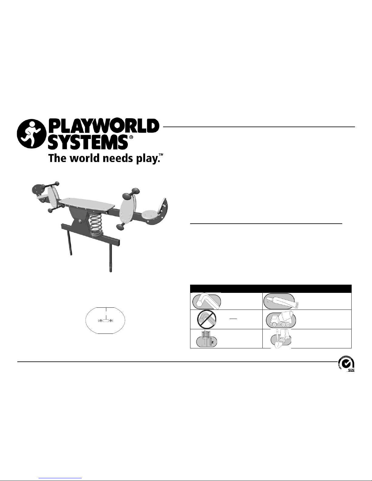
Playworld Systems® Model XX0596
Duo See-Saw
(w/ Seat Backs)
Installation Preparation
Recommended Crew: ...........................Two (2) adults
Installation Time: ...................................3 man-hours
Weight: ..................................................*196.6 lbs. (89,4 Kilos)
Concrete Required: ...............................0.12 cubic yard (0,09 cubic meter)
Use Zone: ..............................................Refer to Use Zone information
User Group: ...........................................Ages 2 - 12 yrs
ICON KEY
Fully Tighten
Hardware
Add 1 Drop of
Thread Locking Adhesive
Do Not Fully TIghten
Hardware
Pour Concrete
Critical Fall Height Dig Footing Holes
Assembly View
A
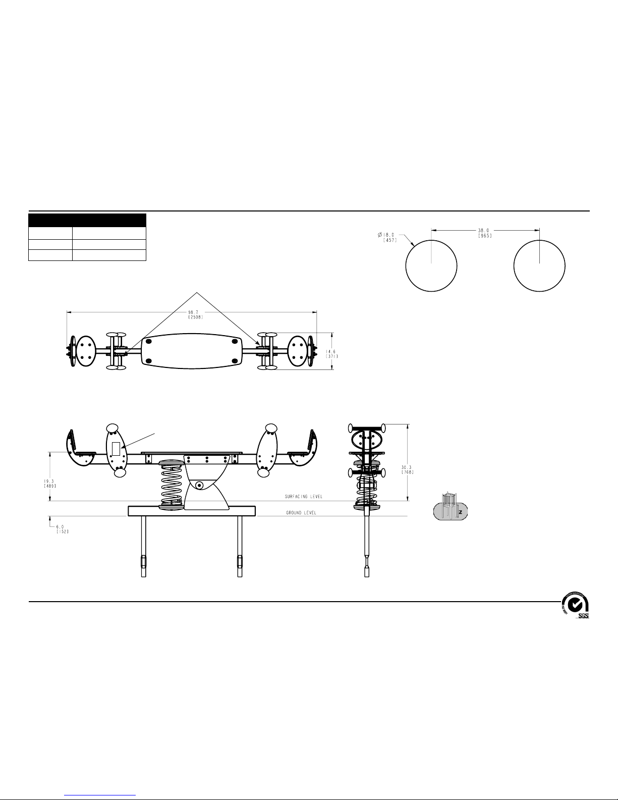
Use Zones: Duo See-Saws
A = ASTM: 84 in. (2134 mm)
CSA: 2100 mm
EN: 1500 mm
*Weights are approximate for determining manpower.
Model XX0596
ECN2463
Page 2 of 14
Installation Instructions
2"
(51 mm)
18"
(457 mm)
Diameter
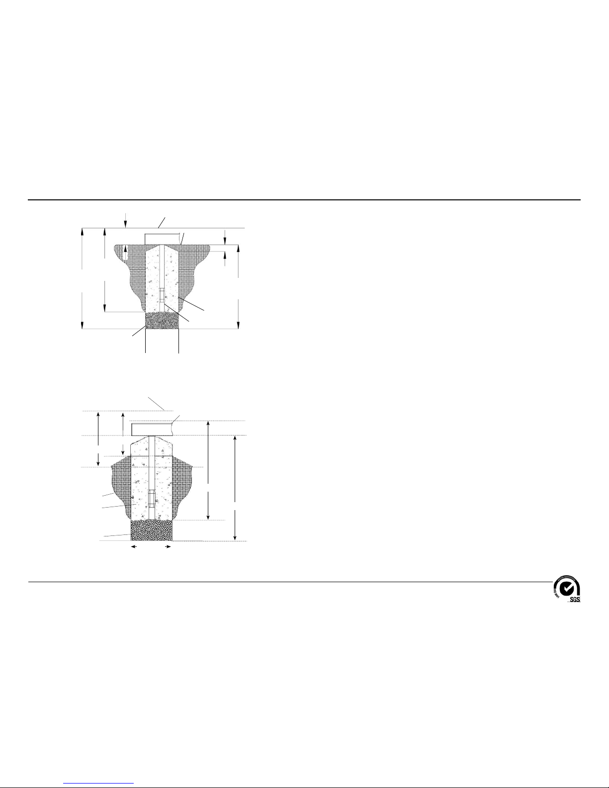
Support Post Footing Detail (ASTM/CSA)
Ground Level
Concrete
Protective Surfacing Level
Support Post
2b Stone
6"
(152 mm)
30"
(914 mm)
36"
(1067 mm)
30"
(914 mm)
FOOTING NOTES
• Support post footing depth equals 36 in. (914 mm) less the depth of the protective
surfacing material. The post is designed to have 24" (610 mm) in concrete.
Example: If 6 in. (152 mm) of wood mulch is used for surfacing, the footing
depth would be 30 in. (762 mm).
• All support posts and component support legs shall have either a factory-applied
sticker with line, or factory-applied mark designating protective surfacing level
on a clear and level installation site.
• If play structure is installed on uneven terrain, maintain support post mark at
protective surfacing level at lowest grade. Adjust other footings accordingly.
Support posts and all attaching decks and play components must be plumb
and level.
• Do not encase bottom of support post in concrete. Place post directly on packed
stone.
• The footings shown on Playworld Systems’ documentation are recommendations
based on historical performance in average soil conditions. Footing dimensions
may be modifi ed by the owner based on actual soil conditions.
For example:
- If local soil is loose or unstable, a larger footing may be required.
- If local soil is considered stable, such as bedrock, clay or hard packed earth, a
smaller footing may be used. Before changing footing dimensions, we strongly
recommend that the footings be reviewed and approved by a registered
engineer.
• Base of footing must be below frost line.
• Assemble the entire structure before pouring concrete unless specifi cally
instructed to do so in the individual component installation instructions.
Support Post Footing Detail (EN)
500 mm
400 mm
915 mm
915 mm
Ground Level
Concrete
Protective Surfacing
Level
Component
2b Stone
Soil
455 mm
Diameter
Model XX0596
ECN2463
Page 3 of 14
Installation Instructions
Footing Diagram
Elevation View
Top View
Surfacing Warning Label
Apply The Surface Warning Labels Here
19.3" (489 mm)
KEY
Position
Unit of Measurement
Top #
Inches
Bottom #
[Millimeters]
Model XX0596
ECN2463
Page 4 of 14
Installation Instructions
Follow the details in alphabetical order. For clarifi cation, each detail references the
step description. The step descriptions start on page 10.
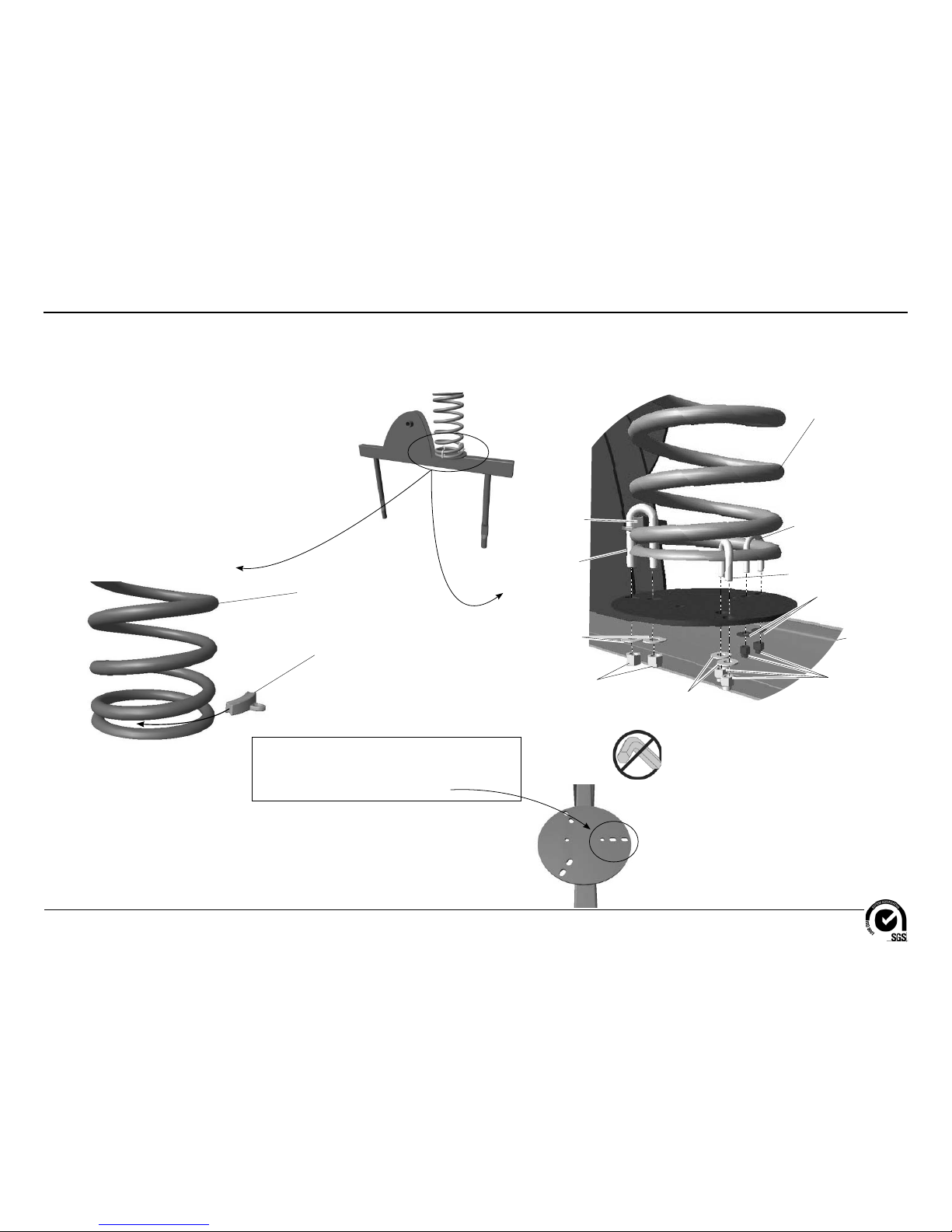
Detail A-1
Step 4
Detail A-2
Step 4
Spring Wedge
AAU0062
Anchor Frame
AFR0696
3/8" Lock Nut
BAE0620
1" O.D. Flat Washer
BAE0600
1" O.D. Flat Washer
BAE0600
1/2" Hex Lock Nut
BAE0720
1.25" O.D. Flat Washer
BAE0690
1/2" x 2.94" U-Bolt
BAE1574
3/8" x 1-1/2" U-Bolt
BAE0027
3/8" x 2" U-Bolt
BAE0028
(See Notes Below)
Spring
ATM0014
Spring
ATM0014
Spring Wedge
AAU0062
Note: Arrange spring as shown in Detail A-2.
Ensure that the 2" U-bolt is lined up with the outer
two holes on the side of the mounting plate that
has three holes arranged in a straight line.
Insert and rotate
around the spring
until snug.
Important Note: The 2.94" U-bolt
attaches through the spring wedge,
then the 2" U-bolt over the second
and bottom coil, and the 1-1/2" U-bolt
over the bottom coil.
Model XX0596
ECN2463
Page 5 of 14
Installation Instructions
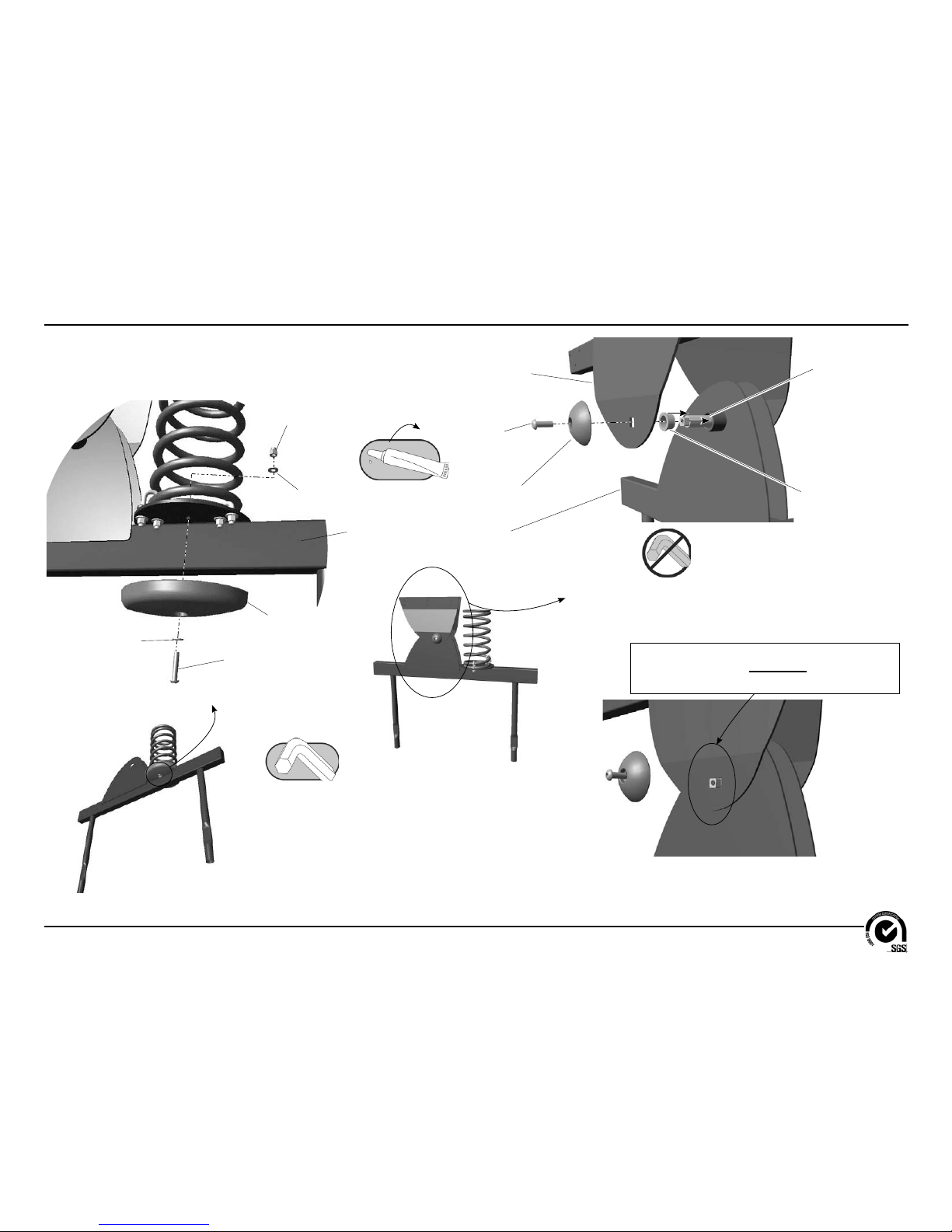
Detail C
Step 7
3/8" x 1"
Button Head Bolt
BAE0664
See-Saw Mounting Plate
APL0520, APL0521
1" I.D. Oilite Bearing
AMC0123
Cross Shaft End Cap
AAU0144
Anchor Frame
AFR0696
.99" O.D. Cross Shaft
ATM0033
(See Important Note
and Detail C-1 below)
Important Note: Ensure that the square portion
of the cross shaft is fully seated in the See-Saw
mounting plate.
Detail B
Step 5
3/8" x 2"
Button Head Bolt
BAE06673
3/8" Flat Washer
BAE0595
Spring Cover Panel
AAU0219
3/8" Flat Washer
BAE0595
3/8" Lock Nut
BAE0620
Anchor Frame
AFR0696
Detail C-1
Step 7

Model XX0596
ECN2463
Page 6 of 14
Installation Instructions
Detail D
Step 8
Cover Panel
Mounting Bracket
ABC0187
See-Saw Frame
AFR0275
3/8" x 3/4"
Button Head Bolt
BAE0659
3/8" Flat Washer
BAE0595
3/8" Flat Washer
BAE0595
Detail F
Step 10
Note: Arrange spring as shown in Detail F. Ensure
that the 2.94" U-bolt is lined up with the outer two
holes on the side of the mounting plate that has
three holes arranged in a straight line.
Detail E
Step 9
3/8" x 3/4"
Button Head Bolt
BAE0659
See-Saw
Mounting Plate
See-Saw Frame
AFR0695
3/8" Flat Washer
BAE0595
3/8" Flat Washer
BAE0595
3/8" Flat Washer
BAE0595
3/8" Hex Nut
w/ Locking Ring
BAE0621
1" O.D. Flat Washer
BAE0600
1" O.D. Flat Washer
BAE0600
1.25" O.D. Flat Washer
BAE0690
1/2" Hex Lock Nut
BAE0720
Spring Wedge
AAU0062
1/2" x 2.94" U-Bolt
BAE1574
(See Notes at Right)
3/8" x 2" U-Bolt
BAE0028
3/8" x 1-1/2" U-Bolt
BAE0027
Important Note: The 2.94" U-bolt
attaches through the spring wedge,
then the 2" U-bolt over the second
and bottom coil, and the 1-1/2" U-bolt
over the bottom coil.
 Loading...