

Playworld Systems XX0549, XX0550 Installation Instructions Manual
Installation Instructions
Models XX0549 & XX0550
ECN 1867
Page 1 of 12
Installation Instructions
Playworld Systems® Models XX0549 & XX0550
Train Spring Rider & Train Spring Rider w/ Sound
Installation Preparation
Recommended Crew: ...........................Two (2) adults
Installation Time: ...................................2 man-hours
Weight: ..................................................100.9 Lbs. (45,8 Kilos)
Use Zone: ..............................................Refer to the information below
User Group Age (years): .......................ASTM/CSA: 2-12, EN: 2-14
Assembly View (representative structure)
Refer to the Elevation View for the specifi c Critical Fall Height for the component.
ICON KEY
Fully Tighten
Hardware
Add 1 Drop of
Thread Locking Adhesive
Do Not Fully Tighten
Hardware
Pour Concrete
Drill Dig Footing Holes
Hammer Critical Fall Height
Spring Rider Use Zones
A = ASTM: 72 in. (1829 mm)
CSA: 1800 mm
EN: 1000 mm
A
Installation Instructions
Models XX0549 & XX0550
ECN 1867
Page 2 of 12
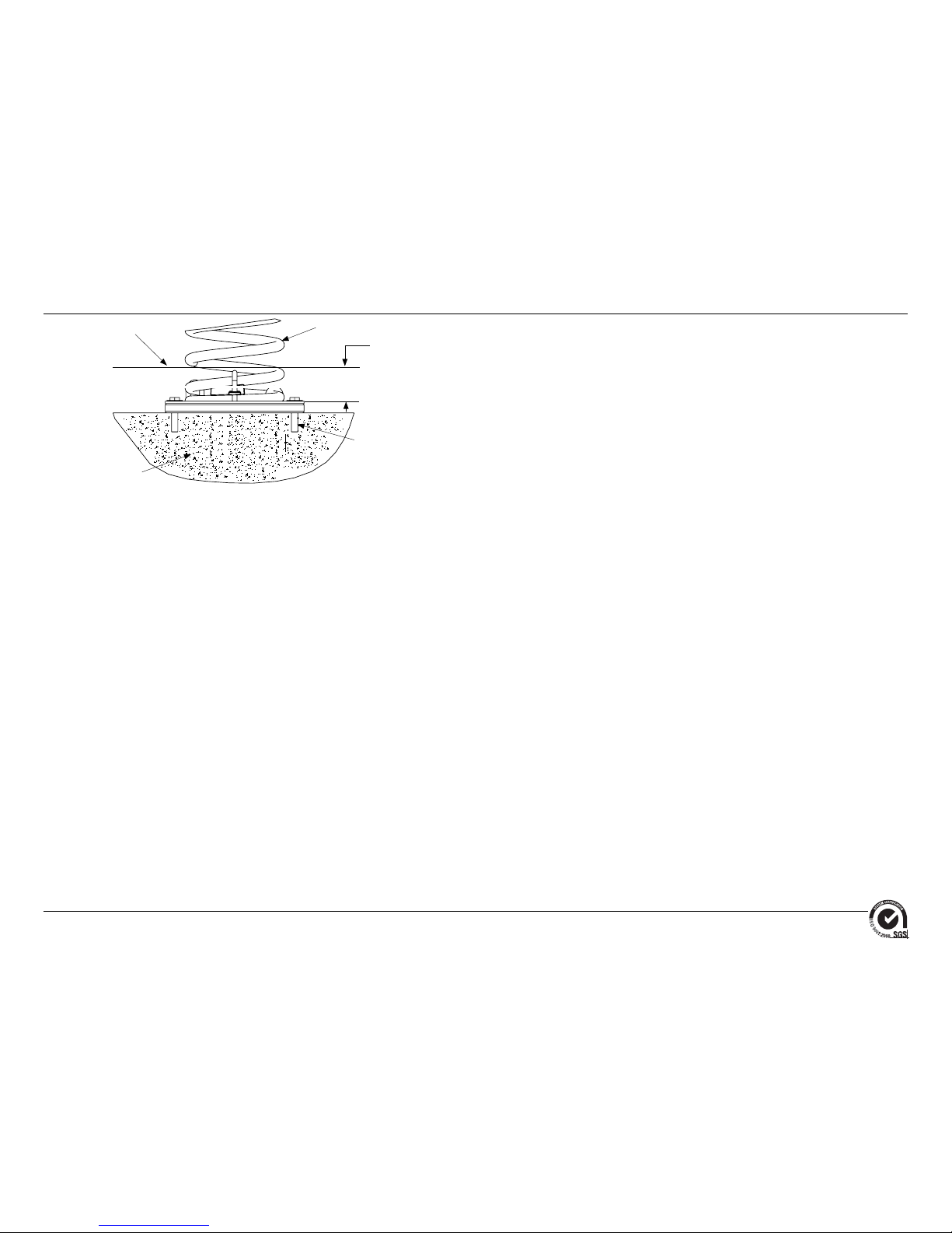
FOOTING NOTES
• Footing size may vary due to local soil and weather conditions.
• The base of the footing must be below frost line.
Surface mount hardware is not supplied. Customer is responsible for
concrete base and providing surface mount hardware as specifi ed by a
registered structural engineer for each specifi c project application.
Concrete Base
Anchor Bolts
Supplied By
Customer
Protective
Surfacing Level
Coil Spring
2" in. (51 mm)
Coil Spring Surface Mount Footing Detail
Installation Instructions
Models XX0549 & XX0550
ECN 1867
Page 3 of 12
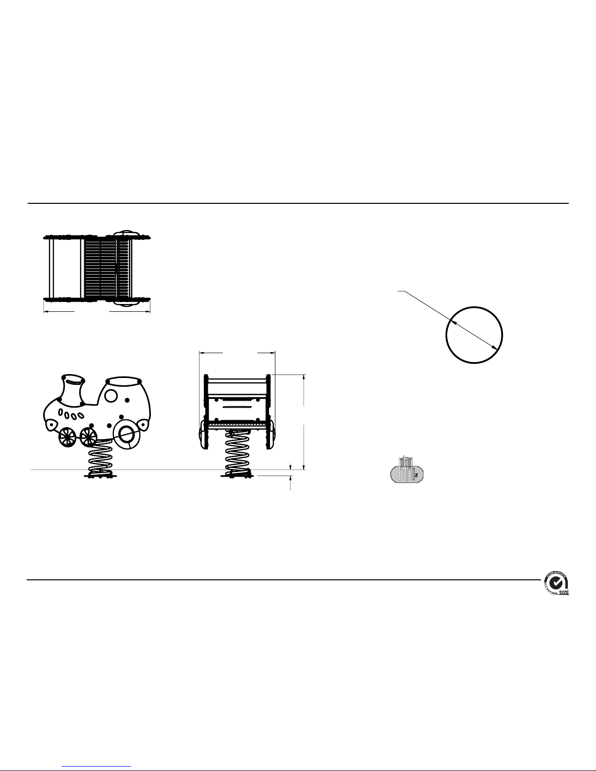
Top View
Elevation Views
XX0549 & XX0550
Footing Diagram
EN: 432 mm
36"
(914 mm)
25.6"
(651 mm)
32.2"
(817 mm)
2"
(51 mm)
Surfacing Level
12"
(305 mm)
Diameter
Installation Instructions
Models XX0549 & XX0550
ECN 1867
Page 4 of 12
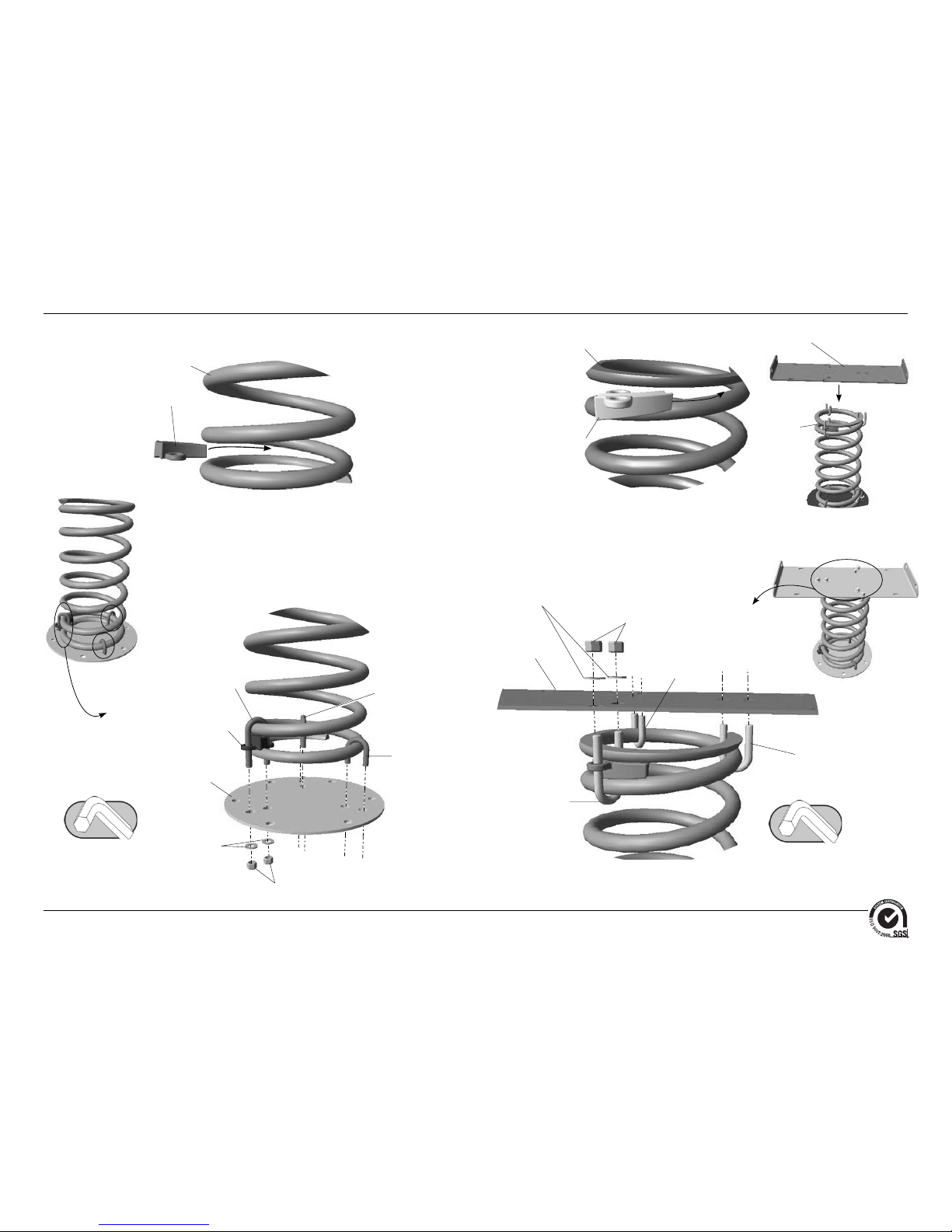
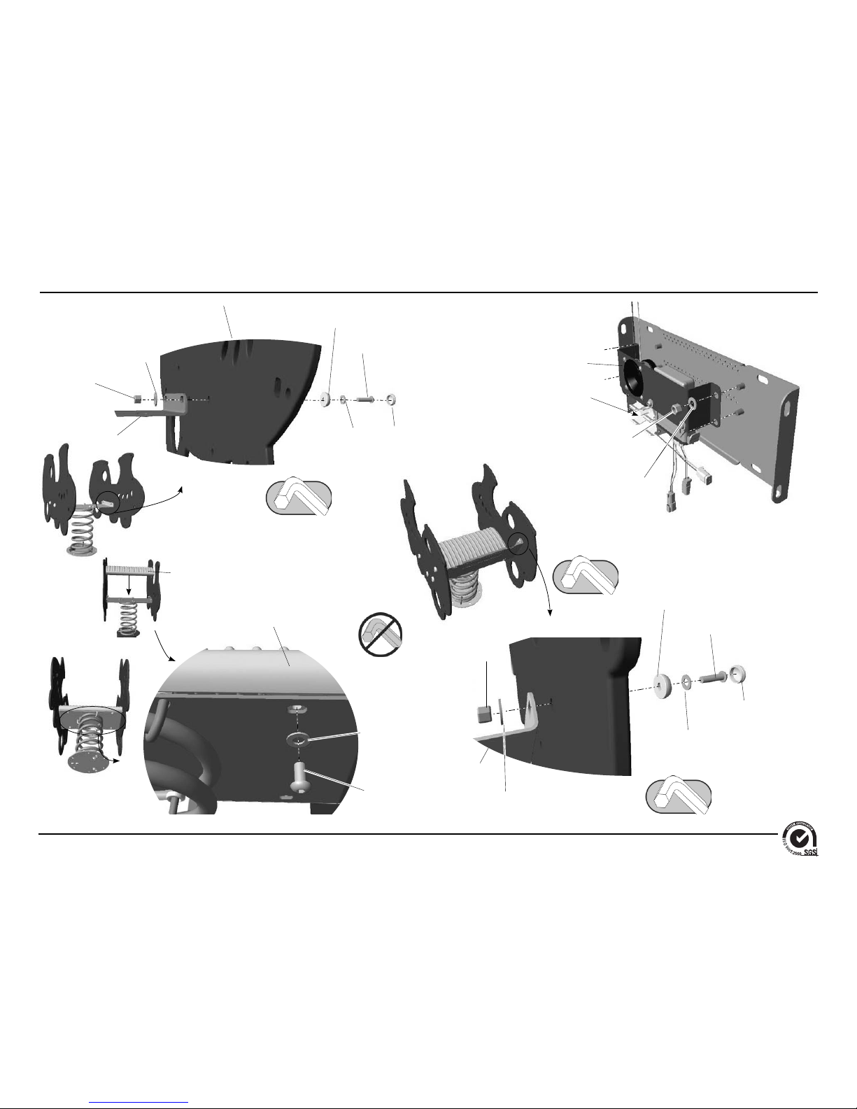
Follow the details in alphabetical order. For clarifi cation, each detail references the
step description. The step descriptions start on page 8.
Detail B-1
Step 5
Detail B-2
Step 5
Detail B-3
Step 5
Spring Wedge Casting
AAU0062
Spring
ATM0014
Spring Wedge Casting
AAU0062
Spring
ATM0014
Metal Platform
ABC0499
Metal Platform
ABC0499
Spring
ATM0014
3/8" x 2"
U-Bolt
BAE0028
3/8" x 1-1/2"
U-Bolt
BAE0027
Hex Nut
w/ Locking Ring
BAE0621
Detail A-2
Step 4
Spring Wedge
AAU0062
Anchor Plate
APL1238
3/8" x 2" U-Bolt
BAE0028
Hex Nut w/ Locking Ring
BAE0621
3/8" x 2-3/4" U-Bolt
BAE0047
3/8" Flat Washer
BAE0595
3/8" Flat Washer
BAE0595
Detail A-1
Step 4
3/8" x 2-3/4" U-Bolt
BAE0047
3/8" x 1-1/2" U-Bolt
BAE0027
Installation Instructions
Models XX0549 & XX0550
ECN 1867
Page 5 of 12
Hex Nut w/ Locking Ring
BAE0621
3/8" Flat Washer
BAE0595
Detail D
Step 7
Detail E
Step 8
3/8" x 1-1/2"
Button Head Bolt
BAE06645
3/8" Flat Washer
BAE0595
3/8" Hex Nut
w/ Locking Ring
BAE0621
1" O.D. Flat Washer
BAE0600
Metal Platform
ABC0499
Train Side Panel
BFC1223
Bolt Cap
BPL0300
Plastic Washer
BPL0300
Important Note: Do Not install bolt caps
until the entire structure is assembled.
3/8" x 3/4"
Button Head Bolt
BAE0659
3/8" Flat Washer
BAE0595
Rider Seat
BPL0266
Rider Seat
BPL0266
Detail C
Step 6
Detail F
Step 9
Note: Skip this step for model XX0549.
Sound Electronics
ASY0149
Note: Sound electronics are factory
ready. No electrical connections will
need to be made.
Insert D-Cell
Batteries Here
(Customer Supplied)
Seat Bracket
ABC0498
3/8" Hex Nut
w/ Locking Ring
BAE0621
1" O.D. Flat Washer
BAE0600
Plastic Washer
BPL0300
3/8" x 1-1/2"
Button Head Bolt
BAE06645
Bolt Cap
BPL0300
3/8" Flat Washer
BAE0595
 Loading...