

Playworld Systems XX3170, XX3170S, XX0365S, XX0365 Installation Instructions Manual
Installation Instructions
Models XX3170 and XX3170S
ECN2382
Page 1 of 14
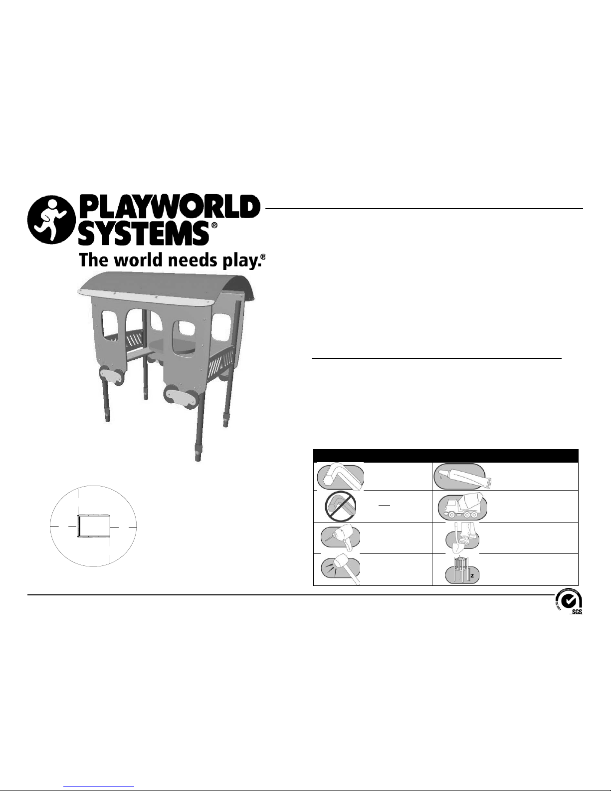
Installation Instructions
Playworld Systems®
Models XX3170 and XX3170S
Dining Car
In-Ground and Surface Mount
Installation Preparation
Recommended Crew: ...........................Two (2) adults
Installation Time: ...................................5 man-hours (in-ground)
Installation Time: ...................................3 man-hours (surface mount)
Concrete Required: ...............................0.12 cubic yard (0,09 cubic meters)
Use Zone: ..............................................Refer to the information below
User Group Age (years): ....................... ASTM/CSA: 2-12, EN: 2-14
Assembly View (representative model)
ICON KEY
Fully Tighten
Hardware
Add 1 Drop of
Thread Locking Adhesive
Do Not Fully Tighten
Hardware
Pour Concrete
Drill Dig Footing Holes
Hammer Critical Fall Height
A
A
A
A
Equipment Use Zone
A - (ASTM) 72 in. (1830 mm)
(CSA) 1800 mm
(EN) 1500 mm
Refer to the Elevation View for the specifi c Critical Fall Height for the component.
Installation Instructions
Models XX3170 and XX3170S
ECN2382
Page 2 of 14
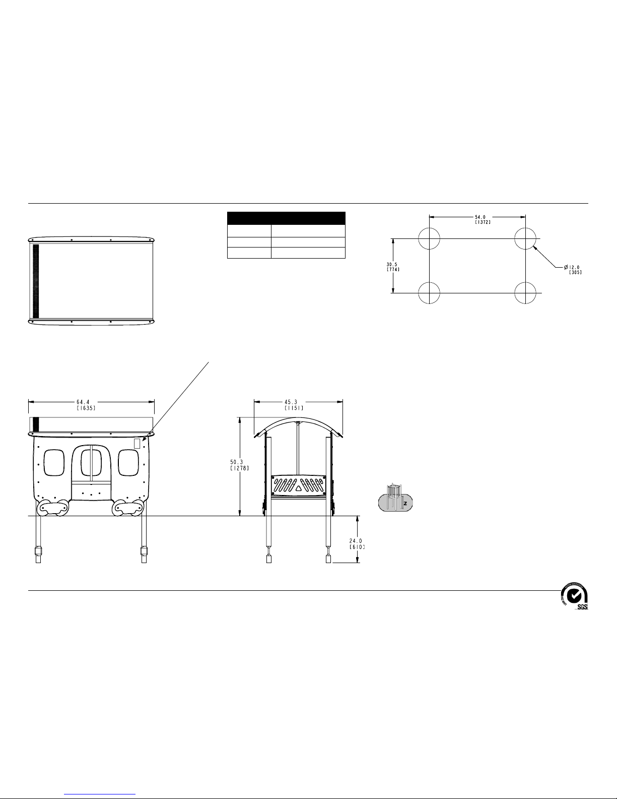
Top View
Elevation Views
XX3170
Footing Diagram
12.6" (320 mm)
KEY
Position
Unit of Measurement
Top #
Inches
Bottom #
[Millimeters]
Apply Surfacing Warning Labels Here
and on Opposite Side
(see Arrows)
Installation Instructions
Models XX3170 and XX3170S
ECN2382
Page 3 of 14
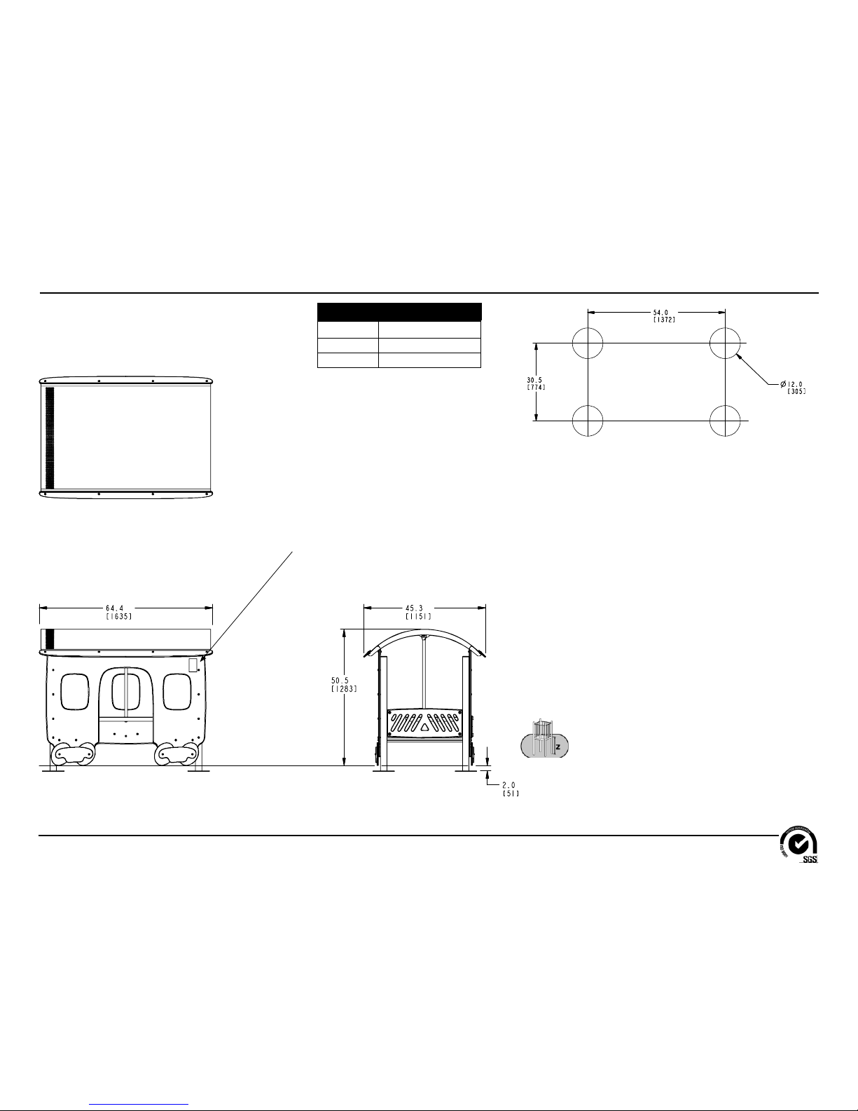
Top View
Elevation Views
XX3170S
Footing Diagram
KEY
Position
Unit of Measurement
Top #
Inches
Bottom #
[Millimeters]
12.6" (320 mm)
Apply Surfacing Warning Labels Here
and on Opposite Side
(see Arrows)
Installation Instructions
Models XX3170 and XX3170S
ECN2382
Page 4 of 14
Follow the details in alphabetical order. For clarifi cation, each detail references the
step description. The step descriptions start on page 9.
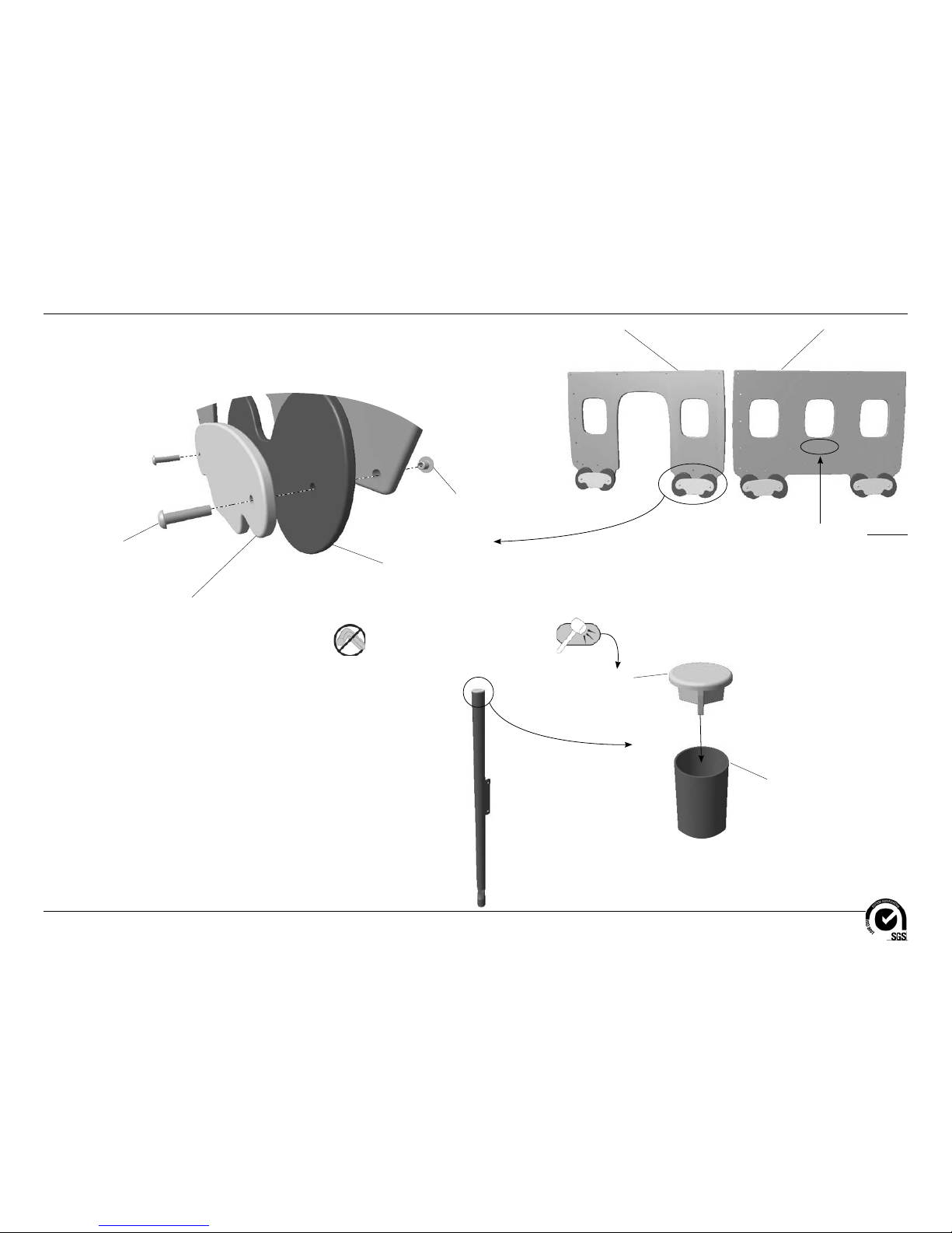
Door Panel
BFC0293
(1 T otal)
3/8" x 1-1/2"
Button Head Bolt
BAE06645
(8 T otal)
Wheel Cover
BFC0307
(4 T otal)
12" Dia. Wheel
BFC0303
(4 T otal)
3/8" Button Head Nut
BAE0663
(8 T otal)
Window Panel
BFC0294
(1 T otal)
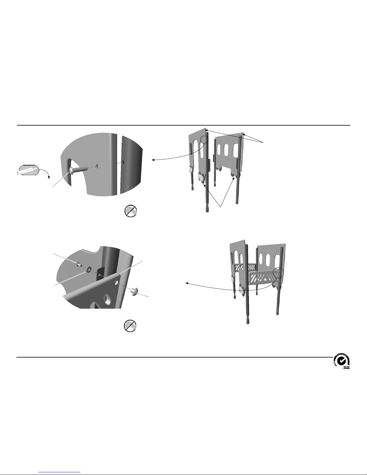
Important Note: Place the wheels on the opposite
side of the window panel that has three larger counter
bored holes in the center.
Detail A
Step 4
Attach the wheels to the door and window panels.
End Cap
AAU0198
(4 T otal)
Support Post
AFM0503 (in-Ground)
AFM0501 (Surface Mount)
(4 T otal)
Detail B
Step 5
Insert the end caps into the support posts.
Installation Instructions
Models XX3170 and XX3170S
ECN2382
Page 5 of 14
3/8" x 1-1/4"
Button Head Bolt
BAE0666
(16 T otal)
Detail C
Step 6
Attach the panel assemblies to the support posts.
Note: The side of the panels with the
wheels must be facing out.
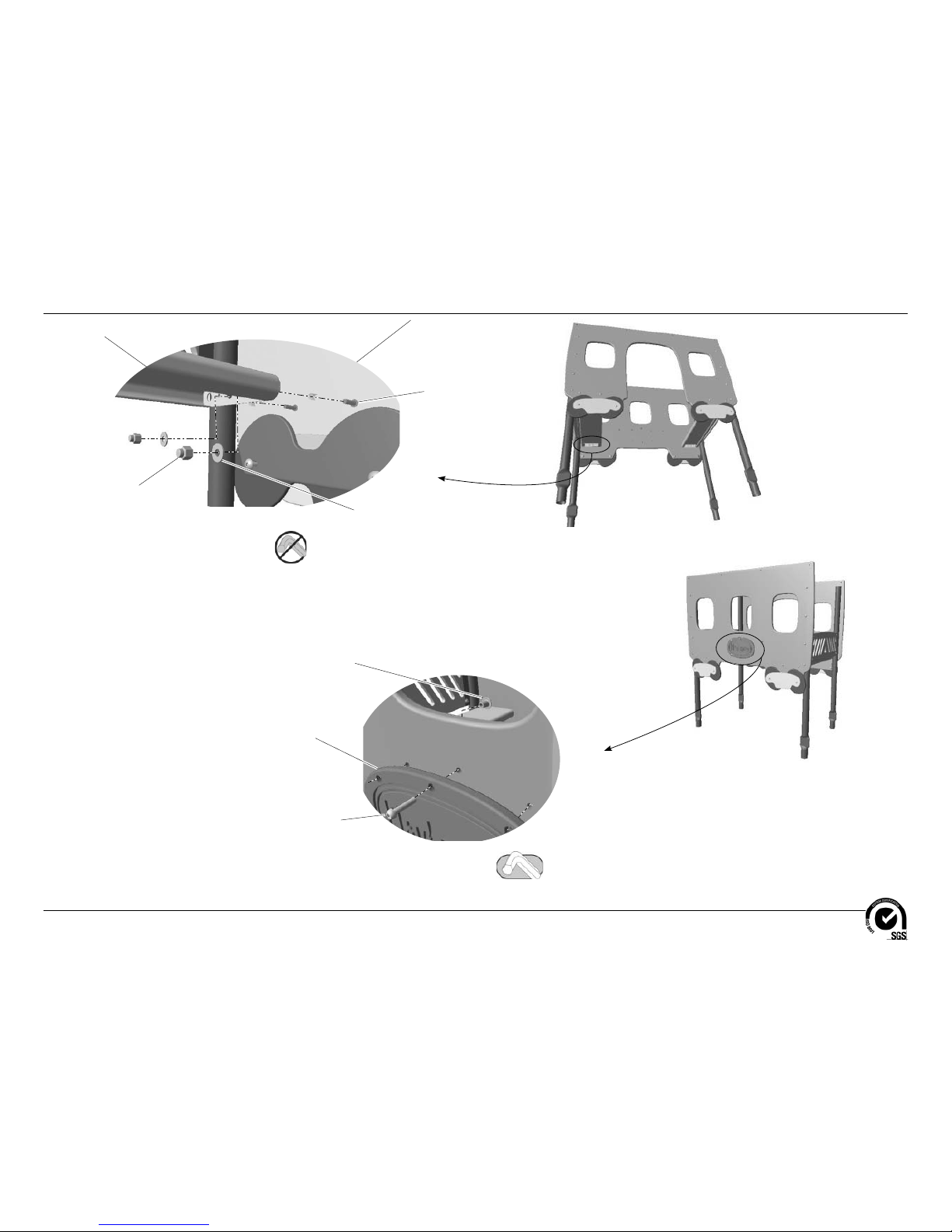
Detail D
Step 7
Attach the backrests to the support posts.
Backrest
BFC0292
(2 T otal)
3/8" x 3/4"
Button Head Bolt
BAE0659
(8 T otal)
1" O.D. Flat Washer
BAE0600
(8 T otal)
3/8" Button Head Nut
BAE0663
(8 T otal)
Note: Leave the top holes on the panels
open for attachment of the roof.
Installation Instructions
Models XX3170 and XX3170S
ECN2382
Page 6 of 14
Window Panel
Panel is shown
transparent for
ease of viewing
the connections.
Detail E
Step 8
Attach the seat planks to the panels.
Seat Plank
BPM0258
(2 T otal)
3/8" x 1-1/2"
Button Head Bolt
BAE06645
(8 T otal)
1" O.D. Flat Washer
BAE0600
(8 T otal)
3/8" Lock Nut
BAE0620
(8 T otal)
Detail F
Step 9
Attach the logo plate to the window panel.
Logo Plate
BFC0299
(1 T otal)
1/4" x 1"
Button Head Bolt
BAE01522
(6 T otal)
1/4" Button Head Nut
BAE0161
(6 T otal)
Installation Instructions
Models XX3170 and XX3170S
ECN2382
Page 7 of 14
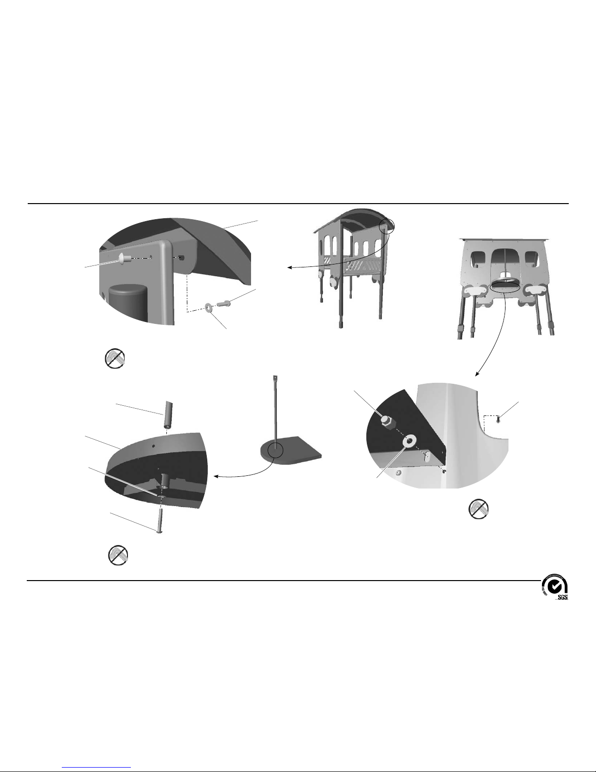
Detail G
Step 10
Attach the roof to the panels.
Roof
AFM0507
(1 T otal)
1/4" x 3/4"
Button Head Bolt
BAE01524
(8 T otal)
1/4" Button Head Nut
BAE0161
(8 T otal)
1/4" Flat Washer
BAE0158
(8 T otal)
Detail H
Step 11
Attach the table support to the table.
3/8" x 2-1/2"
Button Head Bolt
BAE0668
(1 T otal)
1" O.D. Flat Washer
BAE0600
(1 T otal)
Table
BPM0259
(1 T otal)
Table Support
AFM0506
(1 T otal)
Detail I
Step 12
Attach the table to the window panel.
3/8" x 1-1/2"
Button Head Bolt
BAE06645
(2 T otal)
1" O.D. Flat Washer
BAE0600
(2 T otal)
3/8" Lock Nut
BAE0620
(2 T otal)
 Loading...