

Playworld Systems XX0355 Cruise Line Installation Instructions Manual

Installation Instructions
Model XX0355
ECN2579
Page 1 of 16
Installation Instructions
Playworld Systems® Model XX0355
Cruise Line
Installation Preparation
Recommended Crew: ...........................Four (4) adults
Installation Time: ................................... 18 man-hours
Concrete Required: ...............................6.65 cubic yards (5,06 cubic meters)
Use Zone: .............................................. Refer to the information below
User Group Age (years): ....................... ASTM/CSA: 5-12, EN: 6-14
Assembly View
Equipment Use Zone
A - (ASTM) 72 in. (1830 mm)
(EN) 1500 mm
B - (CSA) 1800 mm
ICON KEY
Fully Tighten
Hardware
Add 1 Drop of
Thread Locking Adhesive
Do Not Fully Tighten
Hardware
Pour Concrete
Drill Dig Footing Holes
Hammer Critical Fall Height
A/B
A/B
A/B

Installation Instructions
Model XX0355
ECN2579
Page 2 of 16
Top View
Elevation Views
27" (686 mm)
KEY
Position
Unit of Measurement
Top #
Inches
Bottom #
[Millimeters]
Installation Instructions
Model XX0355
ECN2579
Page 3 of 16
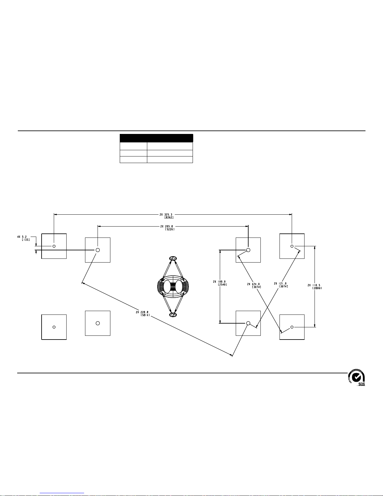
Footing Diagram #1 - Top View
Important Note: Make
sure the footings are laid
out and spaced as shown
in this Footing Diagram.
KEY
Position
Unit of Measurement
Top #
Inches
Bottom #
[Millimeters]

Installation Instructions
Model XX0355
ECN2579
Page 4 of 16
Footing Diagram #2 - Side View and Top View
KEY
Position
Unit of Measurement
Top #
Inches
Bottom #
[Millimeters]

Installation Instructions
Model XX0355
ECN2579
Page 5 of 16
FOOTING NOTES
• Support post footing depth equals 52 in. (1321 mm) less the depth of the protective
surfacing material. The post is designed to have 34" (864 mm) in concrete.
• Some support posts and component support legs may have either a factory-applied
sticker with line, or factory-applied mark designating protective surfacing level on a clear
and level installation site.
• If play structure is installed on uneven terrain, maintain support post mark at protective
surfacing level at lowest grade. Adjust other footings accordingly. Support posts and all
attaching decks and play components must be plumb and level.
• Do not encase bottom of support post in concrete. Place post directly on packed stone
or porous block.
• The footings shown on Playworld Systems’ documentation are recommendations based
on historical performance in average soil conditions. Footing dimensions may be modifi ed
by the owner based on actual soil conditions.
For example:
- If local soil is loose or unstable, a larger footing may be required.
- If local soil is considered stable, such as bedrock, clay or hard packed earth, a smaller
footing may be used. Before changing footing dimensions, we strongly recommend that
the footings be reviewed and approved by a registered engineer.
• Base of footing must be below frost line.
• Assemble the entire structure before pouring concrete unless specifi cally instructed to
do so in the individual component installation instructions.
Support Post Footing Detail
Ground
Level
Concrete
Protective
Surfacing
Level
2b Stone
34"
(864 mm))
52"
(1321 mm)
34"
(864 mm)
Square
Installation Instructions
Model XX0355
ECN2579
Page 6 of 16
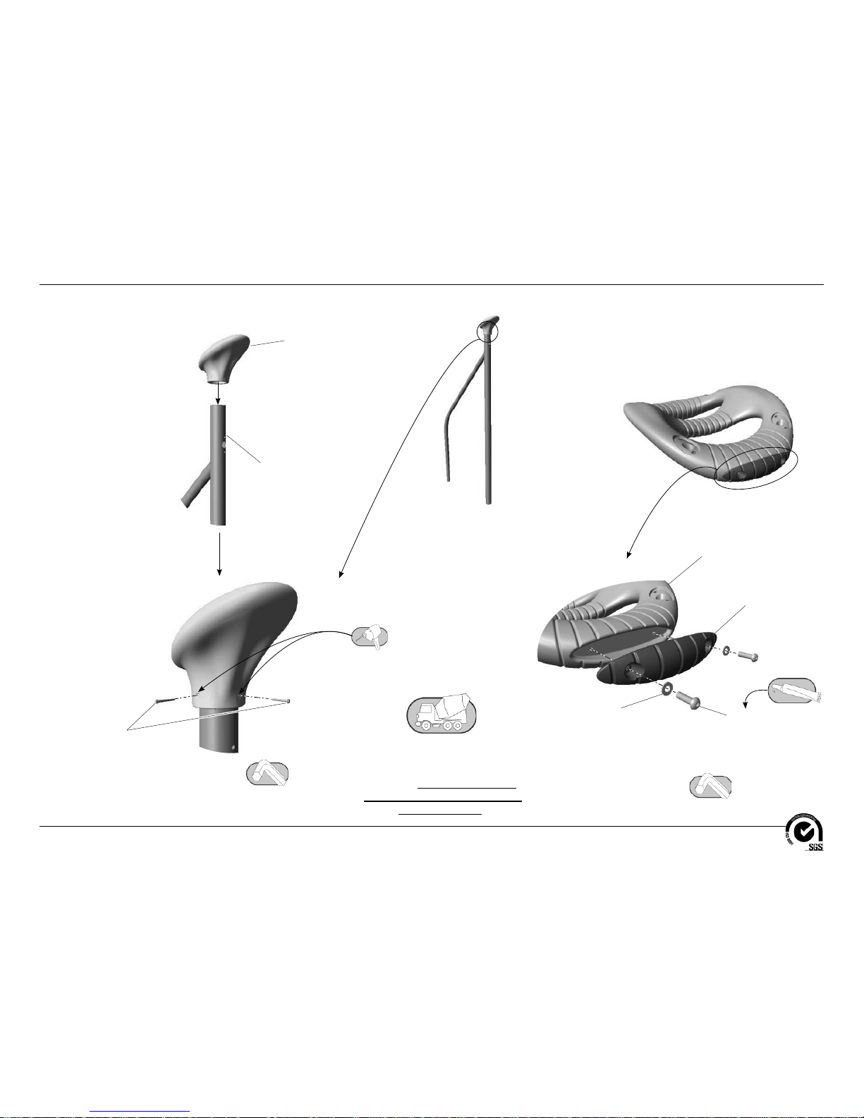
Follow the details in alphabetical order. For clarifi cation, each detail references the
step description. The step descriptions start on page 13.
Detail A
Step 4
Attach the post caps to the support frames.
Support Frame
AFR1474
(4 Total)
#12 x 2"
Self Threading Screw
BAE0015
(8 Total)
Post Cap
BPL0313
(4 Total)
Cruise Line Platform
BPL3175
(1 Total)
Cruise Line Bumper
AAU0790
(2 Total)
3/8" Flat Washer
BAE0595
(4 Total)
3/8" x 1-1/4"
Button Head Bolt
BAE0666
(4 Total)
Detail B
Step 6
Attach the bumpers to the platform.
Step 5
Place the support frames in their
footings. Block and brace for
concrete. Pour concrete and
allow 72 hours for concrete to
completely cure.
 Loading...