

Page 1

Models PM6838 and PM6838S
PA1231
Page 1 of 10
Installation Instructions
Installation Instructions
Playmakers® Models PM6838 and PM6838S
Vine Climber w/Roto
In-Ground and Surface Mount
Installation Preparation
Recommended Crew: ........................... Two (2) adults
Installation Time (in-ground): ................. 4 man-hours
Installation Time (surface mount): ......... 1.5 man-hours
Concrete Required (in-ground only): ..... 0.15 cubic yard (0,10 cubic meters)
Use Zone: .............................................. Refer to Master Drawing
User Group Age (years): ....................... ASTM/CSA: 5-12, EN: 6-14
ICON KEY
Fully Tighten
Hardware
Add 1 Drop of
Thread Locking Adhesive
Do Not Fully TIghten
Hardware
Pour Concrete
Drill Dig Footing Holes
Hammer Critical Fall Height
Assembly View (representative model)
Page 2
Installation Instructions
Models PM6838 and PM6838S
PA1231
Page 2 of 10
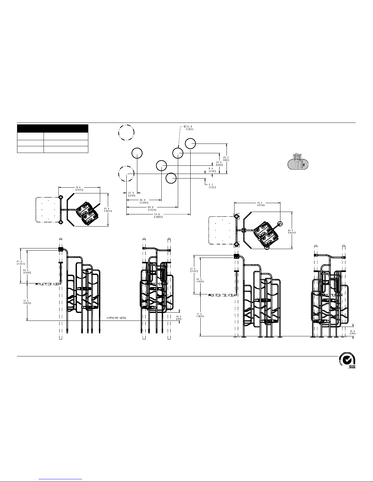
Top View
Elevation Views
PM6838
KEY
Position
Unit of Measurement
Top #
Inches
Bottom #
[Millimeters]
Elevation Views
PM6838S
Top View
123" (3123 mm)
Footing Diagram
Both Models
Page 3
Models PM6838 and PM6838S
PA1231
Page 3 of 10
Installation Instructions
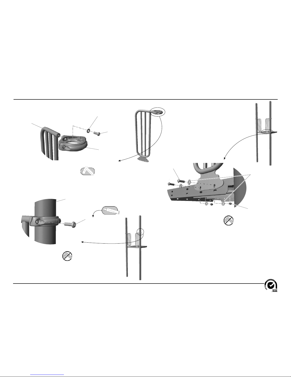
Detail A
Step 4
Attach the clamps to the barrier
gates.
Follow the details in alphabetical order. For clarifi cation, each detail references the
step description. The step descriptions start on page 8.
Detail B
Step 5
Attach the barrier gates to the
support posts.
Detail C
Step 6
Attach the barrier gates to the deck.
Support Post
3/8" x 1-1/4"
Tamper Resistant Bolt
BAE0662
(2 Total)
Barrier Gate
AEN0171
(2 Total)
3/8" Flat Washer
BAE0595
(2 Total)
3/8" x 1"
Button Head Bolt
BAE0664
(2 Total)
Centerline Clamp
AAU0551
(2 Total)
3/8" x 1"
Button Head Bolt
BAE0664
(4 Total)
1" O.D. Flat Washer
BAE0600
(8 Total)
3/8" Lock Nut
BAE0620
(4 Total)
Page 4

Installation Instructions
Models PM6838 and PM6838S
PA1231
Page 4 of 10
Model
72" Vine Climber
Part Number
60" FS Climber
Part Number
60" Center Climber
Part Number
ZZPM6838 ACL0301 ACL0302 ACL0303
ZZPM6838S ACL0317 ACL0318 ACL0319
Detail D
Step 7
Attach the climber support bar to
the support posts.
Detail E
Step 8
Attach the 72" vine climber to the
climber support bar.
Detail F
Step 9
Attach the 60" FS climber to
the vine climber.
Climber Support Bar
AFM4896
(1 Total)
Wide Band Clamp
AAU0021
(2 Total)
Support Post
3/8" Flat Washer
BAE0595
(8 Total)
3/8" x 1-1/4"
Tamper Resistant Bolt
BAE0662
(8 Total)
72" Vine Climber
See Table
(1 Total)
Climber Adaptor
AAU0676
(1 Total)
3/8" x 2-1/2"
Button Head Bolt
BAE0668
(1 Total)
60" FS Climber
See Table
(1 Total)
Climber Adaptor
AAU0676
(1 Total)
3/8" x 2-1/2"
Button Head Bolt
BAE0668
(1 Total)
72" Vine Climber
Page 5

Models PM6838 and PM6838S
PA1231
Page 5 of 10
Installation Instructions
Detail H
Step 11
Attach the 60" center climber to
the 60" FS climber.
60" Center Climber
See Table on previous page
(1 Total)
Climber Adaptor
AAU0676
(1 Total)
3/8" x 2-1/2"
Button Head Bolt
BAE0668
(1 Total)
Detail G
Step 10
Attach the support rungs to the
climbers.
3/8" x 2-1/2"
Button Head Bolt
BAE0668
(4 Total)
3/8" x 1-3/4"
Button Head Bolt
BAE0665
(4 Total)
Support Rung
ARG0466
(4 Total)
60" FS Climber
72" Vine Climber
60" FS Climber
Page 6

Installation Instructions
Models PM6838 and PM6838S
PA1231
Page 6 of 10
Detail I
Step 12
Attach the plank rungs to the
climbers.
Detail J
Step 13
Attach the planks to the
plank rungs.
Plank Rung
ARG0464
(2 Total)
3/8" x 1"
Button Head Bolt
BAE0664
(4 Total)
1" O.D. Flat Washer
BAE0600
(8 Total)
3/8" Lock Nut
BAE0620
(4 Total)
Climber Plank
BPL3126
(2 Total)
3/8" x 1"
Button Head Bolt
BAE0664
(8 Total)
1" O.D. Flat Washer
BAE0600
(8 Total)
Page 7

Models PM6838 and PM6838S
PA1231
Page 7 of 10
Installation Instructions
Detail L-1
Step 16
Detail L-2
Step 16
Secure the clamps to the
support posts.
Wide Band Clamp
Centerline Clamp
Drive Rivet
BAE0020
(2 Total)
Drive Rivet
BAE0020
(2 Total)
Detail K
Step 14
Attach the ropes to the
climbers.
Place the shackle through the
eye of the rope.
Insert the bolt through the
smooth side of the shackle fi rst.
7/16" x 1.5" Button Head Bolt
BAE0702
(supplied with the rope)
Shackle
BAE1572
(supplied with the rope)
Straight Rope
AMC0463
(4 Total)
Page 8

Installation Instructions
Models PM6838 and PM6838S
PA1231
Page 8 of 10
Notes Before You Begin: Do not over tighten bolts during assembly, only snug
tighten them until assembly is complete.
Carefully read and understand these installation instructions before you
begin.
Step 1: Before attempting to assemble your equipment, please review all
installation information carefully. Should you experience any diffi culty during the
installation process, please call us at the phone number shown on the last page
of these instructions.
Step 2: Separate and identify all components and hardware.
Step 3: Excavate, or prepare, the footings as shown in the Component or Surface
Mount Footing Details in the Challenger Guidelines.
Step 4: Attach the clamps to the barrier gates. See Detail A. Position the neck
of the clamp over the top rail of the gate and attach as shown. Fully tighten the
connections. Ensure both clamps are turned in the same direction.
Step 5: Attach the barrier gates to the support posts. See Detail B. Position each
gate against the deck with the clamp closed around the support post. Apply a drop
of thread locking adhesive to the bolt threads, and attach as shown.
Step 6: Attach the barrier gates to the deck. See Detail C. Align the holes in the
barrier gate tabs with the upper holes in the deck and attach as shown.
Note: In the event of a clamp confl ict with an adjacent component, the barrier
gates may be attached to the lower holes in the deck.
Step 7: Attach the climber support bar to the support posts. See Detail D. Position
the climber support bar between the support posts, apply a drop of thread locking
adhesive to the bolt threads, and attach as shown.
Step 8: Attach the 72" vine climber to the climber support bar. See Detail E.
Position the climber adaptor against the top of the vine climber and then against
the climber support bar, and attach as shown. Coped end of the adaptor must be
fl ush against the support bar.
Step 9: Attach the 60" FS climber to the 72" vine climber. See Detail F. Position
the climber adaptor against the top of the FS climber and then against the vine
climber, and attach as shown. Coped end of the adaptor must be fl ush against
the 72" vine climber.
Step 10: Attach the support rungs to the climbers. See Detail G. Position each
support rung between an 60" FS climber and the 72" vine climber, align the holes,
and attach as shown.
Step 11: Attach the 60" center climber to the 60" FS climber. See Detail H. Position
the climber adaptor against the top of the 60" center climber and then against the
60" FS climber, and attach as shown. Coped end of the adaptor must be fl ush
against the FS climber.
Step 12: Attach the plank rungs to the mounting brackets on the climbers. See
Detail I. Position the rungs between the climbers and on top of the brackets.
Attach as shown. Fully tighten the connections.
Step 13: Attach the planks to the plank rungs. See Detail J. Position each plank
onto a rung and attach as shown. Fully tighten the connections.
Step 14: Attach the ropes to the climbers. See Detail K. Position each rope between
the mounting tabs on two climbers, apply a drop of thread locking adhesive to the
bolt threads, and attach as shown. Fully tighten the connections.
Final Details.
Step 15: Plumb and level the component. Tighten all fasteners. Fully tighten all
fasteners according to tightening torque specifi cations.
Torque Specifi cations:
Bolts and nuts - Snug tighten and then tighten an additional one half turn.
In-ground: Block and brace for concrete. Pour concrete after all equipment has
been assembled. Allow 72 hours for concrete to completely cure.
Surface Mount: Bolt down all surface mount supports in accordance with
specifi cations provided by your registered structural engineer.
Important Note: Surface mount hardware is not supplied. Customer is responsible
for concrete base and for providing surface mount hardware as specifi ed by a
registered structural engineer for each specifi c project application.
Page 9

Models PM6838 and PM6838S
PA1231
Page 9 of 10
Installation Instructions
Step 16: Install drive rivets. See Details L-1 and L-2. After the equipment
assembly is complete, install a drive rivet in each clamp to permanently secure
it to the support post. Using a 1/4" drill bit, drill through the clamp and support
post. Insert the drive rivet into drilled hole until the head of the rivet is against the
surface of the clamp. Using a hammer, drive the pin of the rivet until it is fl ush
with the surface of the rivet head.
Note: This step should be executed after structure has been assembled and
properly footed.
Page 10

Installation Instructions
Models PM6838 and PM6838S
PA1231
Page 10 of 10
Bill of Materials
PM6838 - VINE CLIMBER w/ROTO
PART NO. DESCRIPTION QTY.
AAU0021 CLAMP - 5" WIDE ALUMINUM 2
AAU0551 CLAMP - 5" CENTERLINE DIE CAST 2
AAU0676 CASTING - GEO CLIMBER ADAPTER 3
ACL0301 CLIMBER - 72" VINE 1
ACL0302 CLIMBER - 60" VINE FS 1
ACL0303 CLIMBER - 60" VINE CENTER 1
AEN0171 BARRIER - 13.00" x 42.19" GATE 2
AFM4896 FAB METAL - 7.01" x 6.31" x 35.74" 1
AMC0463 21.50" STRAIGHT ROPE w/2 SHACKLES 4
ARG0464 RUNG - 1.315" x 21.88" w/FLAT ENDS 2
ARG0466 FAB METAL - 1.315" O.D. x 5.32" x 17.19" 4
BAD0085 THREAD LOCKING ADHESIVE 1
BAE0020 RIVET - 1/4" x 11/16" DRIVE 4
BAE0595 WASHER - 3/8" SAE FLAT 10
BAE0600 WASHER - 1" O.D. FLAT 24
BAE0620 NUT - 3/8"-16 LOCK w/NYLON CAP 8
BAE0662 BOLT - 3/8"-16 x 1-1/4" TMPR RESISTANT w/TORX DRV 10
BAE0664 BOLT - 3/8"-16 x 1" BUTTON HEAD - SS 18
BAE0665 BOLT - 3/8"-16 x 1-3/4" BUTTON HEAD - SS 4
BAE0668 BOLT - 3/8"-16 x 2-1/2" BUTTON HEAD - SS 7
BPL3126 PLANK - VINE CLIMBER 2
PM6838S - VINE CLIMBER w/ROTO SURFACE MOUNT
PART NO. DESCRIPTION QTY.
AAU0021 CLAMP - 5" WIDE ALUMINUM 2
AAU0551 CLAMP - 5" CENTERLINE DIE CAST 2
AAU0676 CASTING - GEO CLIMBER ADAPTER 3
ACL0317 CLIMBER - 72" VINE 1
ACL0318 CLIMBER - 60" VINE FS 1
ACL0319 CLIMBER - 60" VINE CENTER 1
AEN0171 BARRIER - 13.00" x 42.19" GATE 2
AFM4896 FAB METAL - 7.01" x 6.31" x 35.74" 1
AMC0463 21.50" STRAIGHT ROPE w/2 SHACKLES 4
ARG0464 RUNG - 1.315" x 21.88" w/FLAT ENDS 2
ARG0466 FAB METAL - 1.315" O.D. x 5.32" x 17.19" 4
BAD0085 THREAD LOCKING ADHESIVE 1
BAE0020 RIVET - 1/4" x 11/16" DRIVE 4
BAE0595 WASHER - 3/8" SAE FLAT 10
BAE0600 WASHER - 1" O.D. FLAT 24
BAE0620 NUT - 3/8"-16 LOCK w/NYLON CAP 8
BAE0662 BOLT - 3/8"-16 x 1-1/4" TMPR RESISTANT w/TORX DRV 10
BAE0664 BOLT - 3/8"-16 x 1" BUTTON HEAD - SS 18
BAE0665 BOLT - 3/8"-16 x 1-3/4" BUTTON HEAD - SS 4
BAE0668 BOLT - 3/8"-16 x 2-1/2" BUTTON HEAD - SS 7
BPL3126 PLANK - VINE CLIMBER 2
1000 Buffalo Road • Lewisburg, PA 17837
www.playworldsystems.com
For Customer Service, Call
800-233-8404 or
570-522-9800
OUTSIDE U.S.
 Loading...