

Playworld Unity Teeter Tunnel XX0182, Unity Teeter Tunnel XX0182S Installation Instructions Manual
Installation Instructions
Installation Instructions
Playworld Systems®
Models XX0182 and XX0182S
Unity Teeter Tunnel
Installation Preparation
Recommended Crew: ...........................Four (4) adults
Installation Time: ...................................12 man-hours (In-Ground)
Installation Time: ...................................9 man-hours (Surface Mount)
Concrete Required (In-Ground): ...........0.78 cubic yard (0,60 cubic meters)
Use Zone: .............................................. Refer to the information below
User Group Age (years): ....................... ASTM/CSA: 5-12, EN: 6-14
A
Page 1 of 20
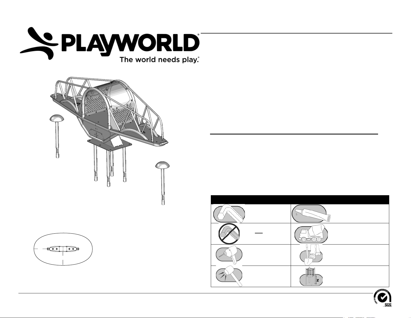
Assembly View (representative model)
Rocking/Springing Equipment
Intended for Standing Use Zones
A = ASTM: 84 in. (2134 mm)
A
CSA: 2100 mm
EN: 1500 mm
ICON KEY
Fully Tighten
Hardware
Do Not Fully Tighten
Hardware
Drill Dig Footing Holes
Hammer Critical Fall Height
Models XX0182 and XX0182S
Add 1 Drop of
Thread Locking Adhesive
Pour Concrete
ECN2664
Installation Instructions
KEY
Position
Top #
Bottom #
Unit of Measurement
Inches
[Millimeters]
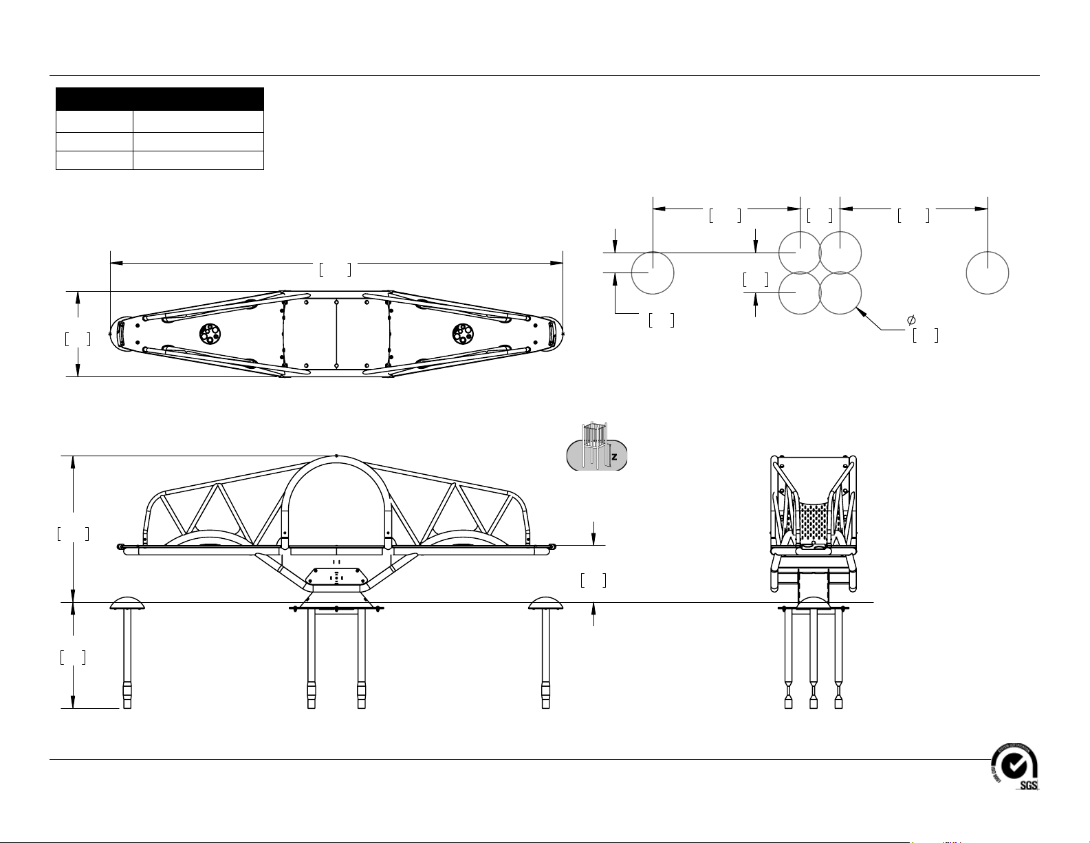
Top View
)227,1*'(7$,/
Footing Diagram
6&$/(
34" (864 mm)
Page 2 of 20
Elevation Views
XX0182
685)$&,1*/(9(/
Models XX0182 and XX0182S
ECN2664
Installation Instructions
KEY
Position
Top #
Bottom #
Unit of Measurement
Inches
[Millimeters]
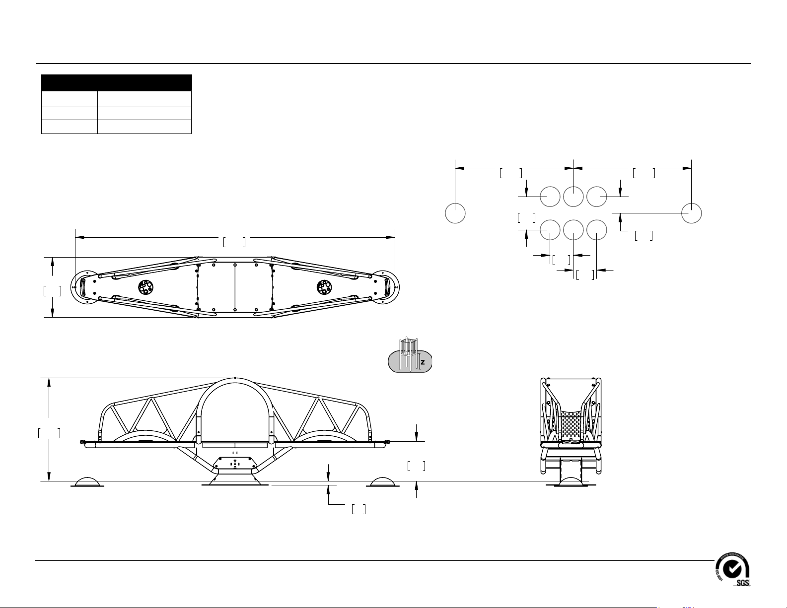
Top View
)227,1*'(7$,/
Footing Diagram
6&$/(
Page 3 of 20
Elevation Views
XX0182S
34" (864 mm)
685)$&,1*/(9(/
Models XX0182 and XX0182S
ECN2664
Installation Instructions
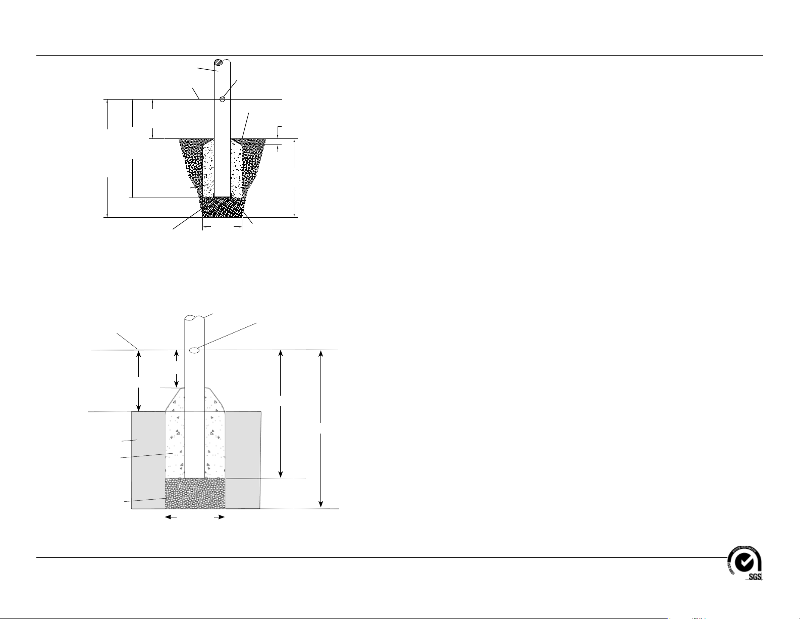
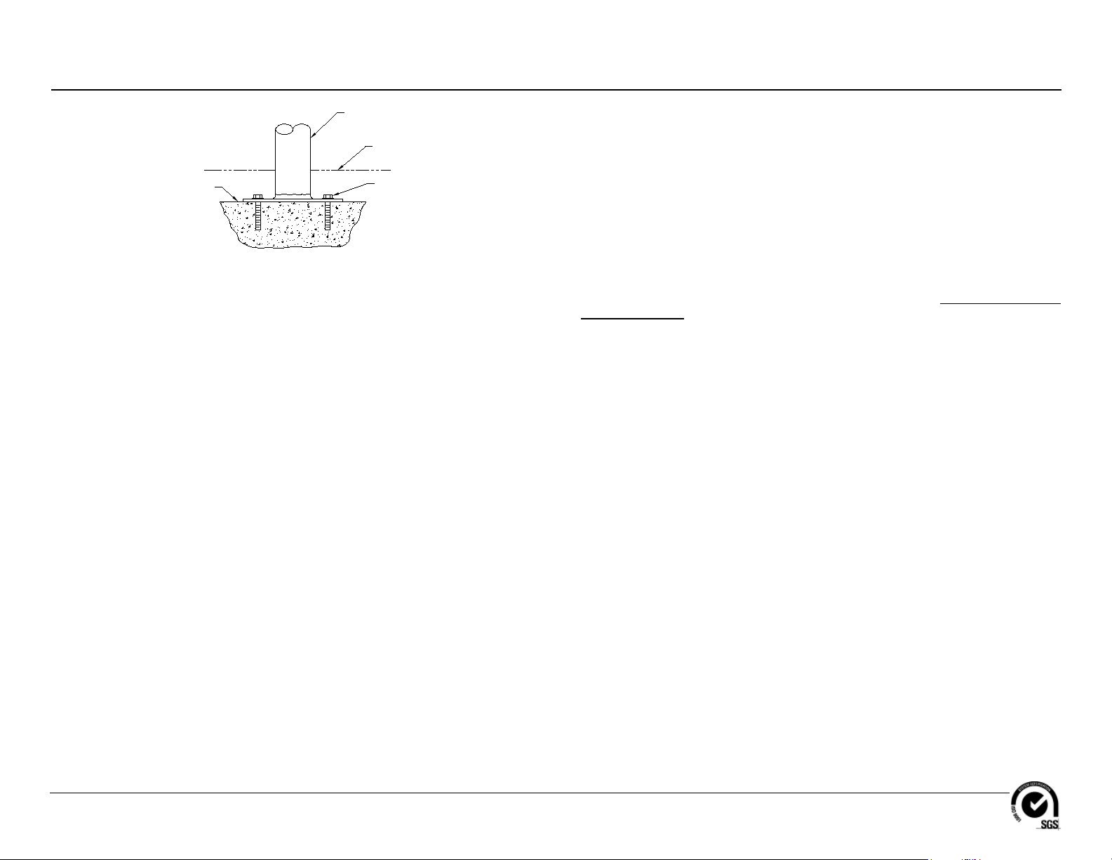
Support Post
Protective Surfacing Level
Varies
36"
(914 mm)
42"
(1067 mm)
Concrete
Factory-Applied Protective
Surfacing Level Sticker
Ground Level
2" (51 mm)
Varies
FOOTING NOTES
• Support post footing depth equals 42 in. (1067 mm) less the depth of the protective
surfacing material. The post is designed to have 24" (610 mm) in concrete.
Example: If 12 in. (305 mm) of wood mulch is used for surfacing, the footing depth would
be 30 in. (762 mm).
• Some support posts and component support legs may have either a factory-applied
sticker with line, or factory-applied mark designating protective surfacing level on a clear
and level installation site.
• If play structure is installed on uneven terrain, maintain support post mark at protective
surfacing level at lowest grade. Adjust other footings accordingly. Support posts and all
attaching decks and play components must be plumb and level.
Support Post Footing Detail (ASTM/CSA)
Protective Surfacing
Ground Level
Concrete
2b Stone
End Cap from
Post Shipping Tube
(Drill holes in cap to allow
for water drainage)
Factory Applied Surfacing Label
915 mm
Soil
2b Stone
400 mm
18"
(457 mm)
Diameter
Support Post
>200 mm
460 mm
Diameter
Footing Detail Support Post (EN)
• Do not encase bottom of support post in concrete. Place post directly on packed stone
or porous block.
• The footings shown on Playworld Systems’ documentation are recommendations based
on historical performance in average soil conditions. Footing dimensions may be modifi ed
by the owner based on actual soil conditions.
For example:
- If local soil is loose or unstable, a larger footing may be required.
- If local soil is considered stable, such as bedrock, clay or hard packed earth, a smaller
footing may be used. Before changing footing dimensions, we strongly recommend that
the footings be reviewed and approved by a registered engineer.
• Base of footing must be below frost line.
• Assemble the entire structure before pouring concrete unless specifi cally instructed to
do so in the individual component installation instructions.
1065 mm
Page 4 of 20
Models XX0182 and XX0182S
ECN2664
Installation Instructions
Concrete Base
Surface Mount Post
Protective
Surfacing Level
Anchor Bolts
Supplied By
Customer
FOOTING NOTES
• All support posts and component support legs may have either a factory-applied sticker
with line, or factory-applied mark designating protective surfacing level on a clear and
level installation site.
• If play structure is installed on uneven terrain, maintain support post mark at protective
surfacing level at lowest grade. Adjust other footings accordingly. Support posts and
all attaching decks and play components must be plumb and level.
• Footing size may vary due to local soil and weather conditions.
Surface Mount Footing Detail
• Base of footing must be below frost line.
• Comparison of protective surfacing materials is available in Handbook for Public
Playground Safety published by U. S. Consumer Product Safety Commission.
Surface mount hardware is not supplied. Customer is responsible for
concrete base and providing surface mount hardware as specifi ed by a
registered structural engineer for each specifi c project application.
Page 5 of 20
Models XX0182 and XX0182S
ECN2664
Installation Instructions
Follow the details in alphabetical order. For clarifi cation, each detail references the
step description. The step descriptions start on page 16.
1/2" x 1-1/2"
Button Head Bolt
BAE0687
(6 Total)
Pivot Base
AFR1606
(1 Total)
See-Saw Bumper
AAU6156
(2 Total)
Anchor Leg
AFR1538
(2 Total)
In-ground model
Page 6 of 20
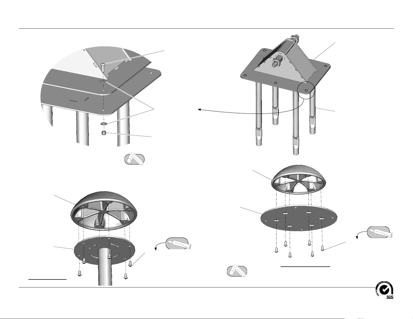
Detail A
Step 4
(In-ground model only)
Attach the anchor frame to the pivot base.
3/8" x 3/4"
Button Head Bolt
BAE0659
(12 Total)
Attach the see-saw bumpers to the anchor legs or brackets.
1/2" Flat Washer
BAE0690
(12 Total)
1/2" Hex Lock Nut
BAE0720
(6 Total)
Anchor Bracket
Detail B
Step 5
Anchor Frame
AFR1559
(1 Total)
See-Saw Bumper
AAU6156
(2 Total)
ABC0906
(2 Total)
3/8" x 3/4"
Button Head Bolt
BAE0659
(12 Total)
Surface mount model
Models XX0182 and XX0182S
ECN2664
Installation Instructions
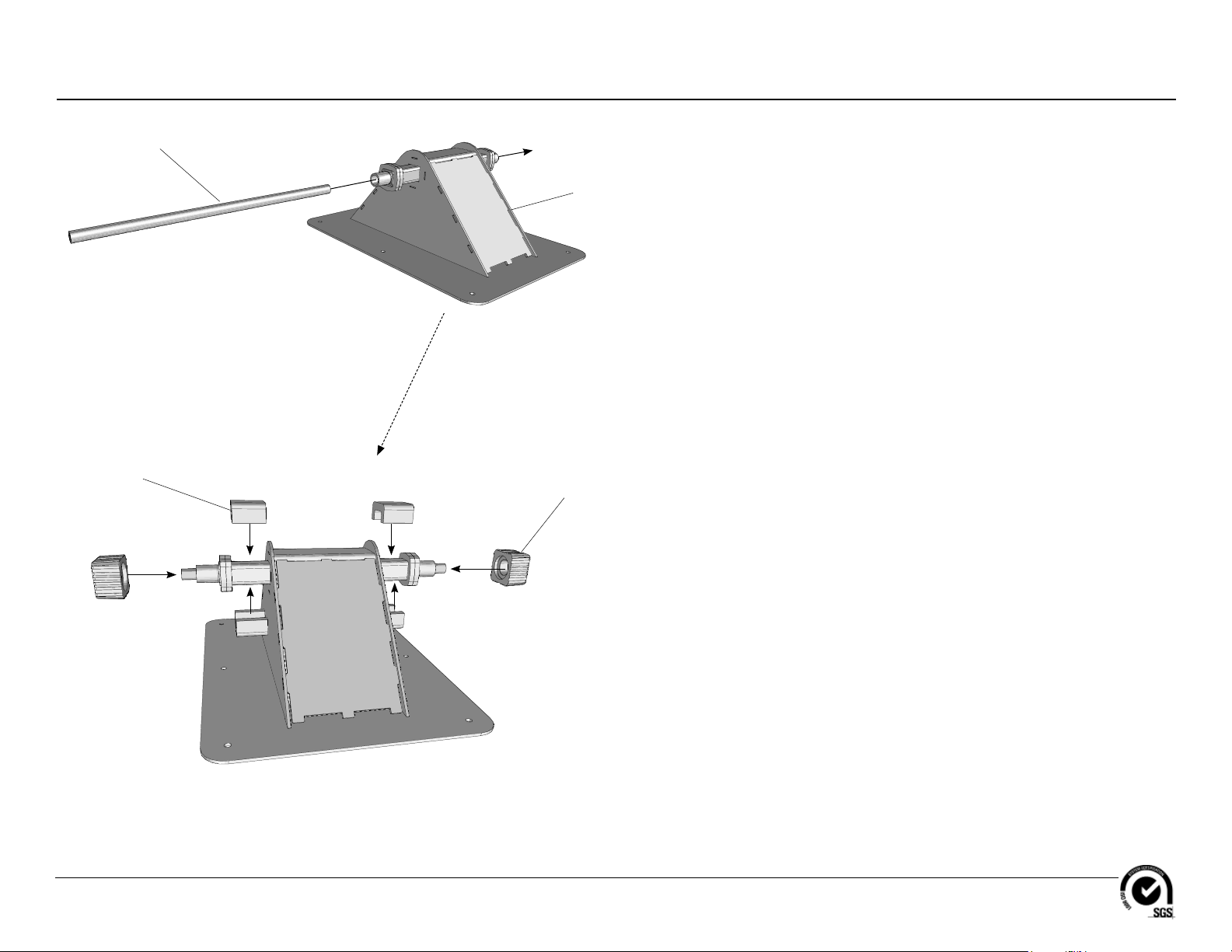
Tie Rod
AFM7999
(1 Total)
3" Bumper
14
AMC01
(4 Total)
Pivot Base
Bushing
AMC01
(2 Total)
15
Page 7 of 20
Detail C
Step 6
Assemble the pivot base.
Models XX0182 and XX0182S
ECN2664
 Loading...