

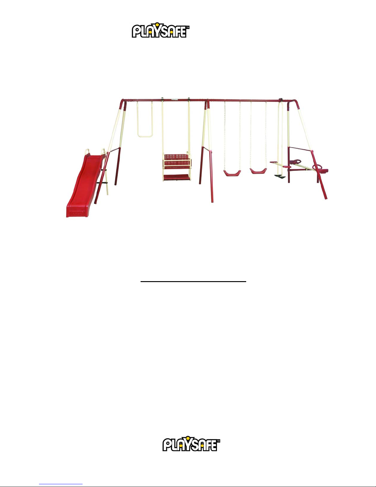
Middleton Swing Set
Owner’s Manual and Assembly Instruction
Model #: 22-PS300S Model Name: Middleton Swing Set
Manual revision: 4/2006
Important: Keep this owner’s manual; do not discard in case you need to contact Pacific Cycle, Inc.
in the future. Should there be a change of ownership, please transfer this manual to the new owner to
ensure proper assembly and safety.
90 DAY LIMITED WARRANTY
Pacific Cycle, Inc. warrants this product to be free of defective materials and workmanship for 90 days from
the date of original purchase.
THIS LIMITED WARRANTY IS THE ONLY WARRANTY APPLICABLE TO THIS PRODUCT,
AND IS EXPRESSLY IN LIEU OF ANY OTHER WARRANTY. ANY IMPLIED WARRANTIES,
INCLUDING ANY WARRANTY OF MERCHANTABILITY AND WARRANTY OF FITNESS
FOR A PARTICULAR PURPOSE, IS LIMITED IN DURATION TO THE DURATION OF THIS
EXPRESS WARRANTY. This limited warranty gives you specific legal rights and you may also have
other rights which may vary from state to state. This warranty is extended only to the original consumer
purchaser for non-commercial use.
PACIFIC CYCLE, INC. IS NOT RESPONSIBLE FOR INCIDENTAL OR CONSEQUENTIAL
DAMAGES. THIS LIMITED WARRANTY DOES NOT COVER ANY PERSONAL INJURIES,
DAMAGE TO, OR FAILURE OF THE PRODUCT OR ANY OTHER LOSSES DUE TO ACCIDENT,
ABUSE, MISUSE, ALTERATION, NEGLECT, NORMAL WEAR AND TEAR, RUST, IMPROPER
ASSEMBLY, IMPROPER FIT, IMPROPER MAINTENANCE OR USE OF UNAUTHORIZED
REPLACEMENT PARTS NOT DESIGNED FOR THE PRODUCT.
1
©
2006 Pacific Cycle, Inc.

To make claim under warranty, notification of such defect must be given to Pacific Cycle, Inc. By calling the phone number
below, you will be instructed on how the product or part needing replacement should be shipped postpaid to Pacific Cycle, Inc.
Customer Service and Assistance
1-800-242-6110
Monday – Friday 8am-5pm CST
Please contact the Playsafe™
need replacement parts for the swing set. You may also contact us by mail:
Playsafe™ Customer Service
Pacific Cycle, Inc
4730 East Radio Tower Lane
Olney, IL 62450
Or by email:
info@Playsafeoutdoors.com
customer service team if you have any questions about our product, need assembly assistance or
WARNINGS AND SAFETY INFORMATION
O
BSERVE ALL WARNINGS AND STATEMENTS IN ORDER TO REDUCE THE RISK OF INJURY OR D E ATH
• BEFORE
STRUCTURE OR OBSTRUCTION TO THE SWING SET
SIDES
O PREVENT SERIOUS INJURY, DO NOT ALLOW CHILDREN TO PLAY ON THE SWING SET UNTIL IT IS
• T
COMPLETELY INSTALLED
O NOT INSTALL THE SWING SET OVER CONCRETE, PACKED DIRT, OR ANY OTHER HARD SURFACE.
• D
A FALL ONTO A HARD SURFACE CAN RESULT IN SERIOUS INJURY OR DEATH TO THE USER
ONLY ADULTS SHOULD ASSEMBLE OR DISASSEMBLE THIS SWING SET
•
HIS PRODUCT MUST BE ANCHORED. ANCHORS ARE SOLD SEPARATELY. CALL
• T
EMAIL
DULT SUPERVISION OF CHILDREN IS REQUIRED AT ALL TIMES WHEN ON OR AROUND THIS SWING SET.
• A
N
EVER LEAVE CHILDREN UNATTENDED
O NOT SWING TOO HIGH OR AT AN ANGLE
• D
O NOT HANG ON OR CLIMB FROM STRUCTURAL MEMBERS OF THE SWING SET
• D
• D
O NOT EXCEED THE INTENDED WEIGHT LIMIT OR MAX IMUM NUM B ER OF USERS FOR THE SWING SET
HE INTENDED AGE FOR USE OF THIS PRODUCT IS 2 YEARS TO 10 YEARS OLD, UNDER ADULT
• T
SUPERVISION
E SURE TO OBSERVE YOUR CHILDREN AND INSURE THAT THEY HAVE THE STRENGTH AND SKILLS TO
• B
ENJOY ALL THE RIDES SAFELY BEFORE USE ON THEIR OWN
• D
O NOT ALLOW CHILDREN TO WALK CLOSE TO, BEHIND, OR IN FRONT OF MOVING ITEMS
O NOT ALLOW CHILDREN TO TWIST SWING CHAINS OR LOOP THEM OVER THE TOP BAR. THIS MAY
• D
REDUCE THE STRENGTH OF THE CHAIN
EACH AND INSTRUCT CHILDREN NOT TO SWING EMPTY SEATS
• T
NSTRUCT CHILDREN HOW TO SIT IN THE CENTER OF THE SEATS AND SWING WITH THEIR FULL WEIGHT
• I
ON THE
ARN CHILDREN NOT TO USE THE EQUIPMENT IN
• W
• W
ARN CHILDREN NOT TO GET OFF THE RIDES WHILE IN MOTION
YOU ASSEMBLE THE SWING SET, FIND LEVEL GROUND NOT LESS THAN 6 FEET FROM ANY
. Y
OUR SWING SET MUST HAVE CLEARANCE ON ALL
.
.
.
.
1-800-242-6110 O
INFO@PLAYSAFEOUTDOORS.COM
.
.
.
. C
HILDREN UNDER 2 YEARS HAVE A HIGHER RISK OF ENTRAPMENT AND INJURY
.
.
.
SEAT.
ANY
MANNER OTHER THAN INTENDED
.
.
.
.
R
.
.
2
©
2006 Pacific Cycle, Inc.

ARN CHILDREN TO DRESS APPROPRIATELY. LOOSE FITTING CLOTHING IS POTENTIALLY HAZARDOUS
• W
WHEN USING THE SWING SET
QUIPMENT MAY BE SLIPPERY WHEN WET. DO NOT ALLOW CHILDREN TO USE THE EQUIPMENT WHEN
• E
.
WET
ARENTS SHOULD REGULARLY CHECK OPENINGS AND SURFACES, SUCH AS SLIDES, FOR ITEMS THAT
• P
MAY BE HAZARDOUS
ARENTS SHOULD CHECK SWING
• P
T
BACK ON
• D
O NOT PLACE ANY PART OF THE BODY NEAR MOVING PARTS ON GLIDE RIDES OR TOP BRACKETS
EVER SLIDE HEAD FIRST DOWN THE SLIDE
• N
• V
ERIFY THAT ALL SWINGS AND CHAINS ARE SECURED AT BOTH ENDS
• NEVER
SET
,
SUCH AS JUMP ROPES, PET LEASHES, ROPE OR CORDS AND OTHER CHAINS AS THESE POSE A
POTENTIAL STRANGULATION HAZARD
HEMSELVES
ATTACH ANY MATERIALS THAT ARE NOT SPECIFICAL LY DESIGNED FOR USE WITH THIS SWING
.
.
CHAINS
TO INSURE THEY ARE SECURE AND CAN NOT BE LOOPED
.
.
.
.
.
PROPER USE
This swing set is designed for use by children ages 2 to 10 under adult supervision. The maximum number of users this
unit is intended for is 9 children with a maximum weight of 105 lbs each. The maximum fall height for this swing set is 7’
or 84”.
Single Ride (i.e. Swing) 105 lbs
Double Ride (i.e. Glider) 210 lbs
This product is designed for normal residential use only. This product is not designed for use in day care, nurseries, or
other public places. This product is to be assembled by adults only in the manner described within this owner’s manual.
The swing set must be anchored.
the section below.
Anchors are not included in this carton. For more information on anchoring, please see
ANCHORING
ANCHORING is necessary to prevent tipping, lifting, and overturning. Playsafe™ recommends anchoring the swing set
in concrete, especially in soft or sandy soil. When this is not possible, anchors can be purchased by calling 1-800-242-6110.
To anchor the swing set in concrete, dig a hole at least 5” deep and 10” to 12” in di a meter. Place the swing set leg in the
hole, preferably on a brick or stone to keep if from sinking. Be sure the swing leg is set 3” below the ground. Also make
sure the swing set is level. The support of the see saw should be anchored in the same manner. Pour concrete around the
legs and fill the hole. Cover concrete adequately using the recommended surfacing instruction in this manual. Allow the
concrete to cure according to the concrete manufacturer’s instruc tion before use.
CONSUMER INFORMATION FOR PLAYGROUND SURFACING MATERIALS
The U.S. Consumer Product Safety Commission estimates that 100,000 playground related injuries are treated annually in U.S.
hospital emergency rooms. Injuries involving this hazard pattern tend to be among the most serious of all playground injuries,
and have the potential to be fatal, particularly when the injury is to the head. The surface under and around the playground
equipment can be a major factor in determining the injury-causing potential of a fall. It is self-evident that a fall on a shockabsorbing surface is less likely to cause a serious injury than a fall onto a hard surface. Playground equipment should never be
placed on a hard surface such as concrete or asphalt and while grass may appear to be acceptable it may quickly turn to hard,
packed earth in areas of high traffic. Shredded bark mulch, wood chips, fine sand or fine gravel are considered to be acceptable
shock absorbing surfaces when installed and maintained at a sufficient depth under and around playground equipment.
3
©
2006 Pacific Cycle, Inc.

The following table lists the maximum height from which a child would not be expected to sustain a life-threatening injury in a
fall onto four different loose-fill surfacing materials if they are installed and maintained at depths of 6, 9, and 12 in. However, all
injuries due to a fall can not be prevented no matter what surfacing materials are used.
FALL HEIGHT IN FEET FROM WHICH A LIFE
THREATENING INJULY WOULD NOT BE EXPECTED
Material Type 6 in. depth 9 in. 12 in.
Double Shredded
Bark Mulch 6’ 10’ 11’
Wood Chips 6’ 7’ 12’
Fine Sand 5’ 5’ 9’
Fine Gravel 6’ 7’ 10’
It is recommended that a shock absorbing material should extend a minimum of 6’ in all directions from the perimeter of the
stationary equipment such as climbers and slides. However, because children may deliberately jump from a moving swing, the
shock absorbing material should extend in front and rear of the swing a minimum distance of 2 times the height of the pivot point
measured from a point directly beneath the pivot on the supporting structure.
The information is intended to assist in comparing the relative shock-absorbing properties of var ious materials. No particular
method is recommended over another. However, every material is only effective when properly maintained. Materials should be
checked periodically and replenished to maintain correct depth as determined necessary for your equipment. The choice of a
material depends on the type and height of the playground equipment, the availability of material in yo ur area and its cost.
(The information above has been extracted from CPSC documents ‘Playground Surfacing – technical Information guide” and
“Handbook for public Playground Safety.” Copies of these documents can be obtained by sending a postcard to the: Office of
Public Affairs, USCPSC, Washington D.C. , 20 2 07 or by ca l l i ng 1- 80 0-638-2772.
CARE AND MAINTENANCE
• Check all nuts and bolts twice monthly during the usage season for tightness and tighten as required. It is particularly
important that all nuts and bolts are checked prior to the first use each season.
• For extended use, remove plastic swing seats and take indoors when the temperature drops below 32º F.
• Oil all metallic moving parts monthly during the usage season.
• Check all coverings for bolts and sharp edges weekly during usage season to be certain they are in place. Replace as
needed. It is particularly important that all coverings are checked prior to the first use each season.
• Sand any rusted areas of the tubing and repaint with a non-lead based paint meeting the requirements of Title 16 CFR
Part 1303.
LOCATION AND PLACEMENT OF YOUR SWING SET
• Place your swing set a MINIMUM of six (6) feet from any other hard or fixed object.
• Do not place your swing set underneath electrical lines. If you must, ensure that there is a minimum overhead
clearance of six (6) feet.
• Please note the CPSC surfacing materials recommendations above.
TOOLS REQUIRED FOR ASSEMBLY
Your swing set comes with two 5mm Allen wrenches for the assembly of most of this product. You may also need to have the
following tools available:
• Adjustable wrench
• Phillips screwdriver
4
©
2006 Pacific Cycle, Inc.

• Needle-nose pl iers
Although we take pride in the quality of our swing sets, on occasion there may be a burr or rough part which will require a metal
file to remove before use.
PARTS LIST FOR SWING SET
Remove all parts from the package and lay them out before you begin assembly. If any parts are missing, please call 1800-242-6110.
Main Frame
Name Each
Top Bar with Hooks 2
Corner Fitting 2
Center Fitting 1
Leg 6
Support Bar 3
See-Saw
Name Each
Seats 2
See Saw Bar 1
Support Bar 1
Ground Fitting 1
Lawn Swing
Name Each
Vertical Tubes 4
Seat/Backrest 4
Foot Plate 2
Arm Rest 2
Seat Support Bar 8
Foot Plate Support Bar 2
Glider
Name Each
Glider Pole (vertical) with Foot Rests 2
Glider Pole (horizontal) with Seats 2
Glider Frame Attachment 1
Swings and Trapeze
Name Each
Swing Seat with Chains 2
Trapeze 1
Slide
Name Each
Rail/Ladder Leg 2
Front Leg 1
Slide 1
Ladder Step 2
PRE-ASSEMBLED HARDWARE
For easier assembly, Playsafe™ has pre-assembled some of the parts for you. Most of the screws and bolts should already be
in place. If removal of this hardware is required for certain assembly steps, it should be replaced in its original position.
Hardware shown in the assembly steps is actual size.
5
©
2006 Pacific Cycle, Inc.

Required Parts:
MAIN FRAME ASSEMBLY
Top Bar x2
Leg x6
Pre-Assembled Parts:
• Swing and trapeze hooks should be in place on the top tube.
• Hardware for legs should be in place in the corner fittings.
• Hardware for support bars should be in place on the legs.
Support Bar x3
Corner Fitting x2 Center Fitting x1
Step Illustration Instructions Hardware Reference
1
Join the two sections of the top bar together
by connecting the center frame fitting with
the hardware that is already placed in the
top bar.
Part Ref. #: PSHW10
2
3
6
Remove the hardware from the center
prong of the corner fitting and insert the top
bar. Once the holes are aligned, re-insert
the hardware.
Repeat the process for the opposite corner
fitting. Then turn the top bar with the
attached corner fittings upside down to
prepare for the legs to be inserted.
©
Part Ref. #: PSHW10
Part Ref. #: PSHW10
2006 Pacific Cycle, Inc.

4
5
Remove the hardware from the corner
fitting prongs. Align the two sets of holes
for each leg and replace the hardware
through the corner fitting prongs to secure
the legs. Do not over tighten the screws.
After all parts are assembled you will need
to tighten again.
Repeat the process for the center legs.
Then stand the swing set onto its legs.
Part Ref. #: PSHW10
Part Ref. #: PSHW10
6
Remove the hardware from the middle
section of a leg. Match up the holes of the
mid-leg and support bar and re-insert the
hardware through both. Repeat the process
for the opposite side and center legs. It
may be necessary to pull both legs towards
each other in order for the holes to align
properly.
NOTE: One support bar has holes for the
slide attachment. The holes should be
positioned toward the front of the swing set.
Part Ref. #: PSHW12
GLIDER ASSEMBLY
Required Parts: Vertical Poles x2 (Footrests attached)
Horizontal Poles x2 (Seats attached)
Glider attachment x1
Pre-Assembled Parts:
• The seats should be attached to the horizontal poles. These must be disassembled to complete the steps below.
• The foot rests should be attached to the vertical poles.
7
©
2006 Pacific Cycle, Inc.

Step Illustration Instructions Hardware Reference
1
Secure the glider attachment with the V-
Part Ref. #: PSHW35, PSHW22
screw and the bolts at the squared portion
of the top bar.
NOTE: The glider must be positioned
adjacent to the outside legs.
2
Attach the two vertical poles to the glider
attachment. Start by removing the
hardware from the lower section of the
glider attachment. Align the vertical bar
with the glider attachment and re-insert the
hardware. Repeat the process for the other
side.
NOTE: The curved portion of the pole is
the top and it should face the inside of the
swing frame.
3
Connect the two horizontal poles (must
first be disassembled from the seats) to the
two vertical poles using the hardware
provided. Be sure that the plastic bushings
are between the vertical poles and
horizontal poles.
4
Reattach the seats onto the horizontal poles
using the flat headed screw, washer, and
lock nut.
Part Ref. #: PSHW21, PSHW36
Part Ref. #: PSHW15, PSHW11
Part Ref. #: PSHW1
8
©
2006 Pacific Cycle, Inc.

5
Once fully assembled, check that the glider
Part Ref. #: PSHW21, PSHW36
swings freely. If it does not, make sure
that the bolts holding the vertical poles to
the top bar attachment are not overly
tightened.
Required Parts:
SEE-SAW ASSEMBLY
See-Saw Bar and Extension Frame Attachment Support Attachment Seat x2
Step Illustration Instructions Hardware Reference
1
9
Remove the hardware from the frame
attachment and connect the extension. Reinsert the hardware and tighten.
NOTE: Be sure that the lower part of the
see-saw extension is buried and anchored
per the anchoring instructions on page 3.
©
Part Ref. #: PSHW10
2006 Pacific Cycle, Inc.

2
3
Secure the frame attachment to the leg of
the frame with the hardware provided on
the leg.
NOTE: Be sure that the see-saw frame
attaches to the leg on the opposite side of
the slide. If the leg with the holes is near
the support bar with the slide attachments,
it should be moved to the other end.
Install the seats on the see-saw bar. Check
the nuts and bolts on the seat so that they
are secure.
Part Ref. #: PSHW10
Part Ref. #: PSHW16
4
5
6
Mount the pivot onto the frame
attachment. The pivot should be between
the two screw heads, starting with the
plastic bushing and then the metal bracket.
Attach the see-saw bar to the pivot using
the hardware found on the see-saw bar.
Once fully assembled, check that the seesaw hinges freely. If it does not, make
sure that the bolts on the see-saw bar are
not overly tightened.
Part Ref. #: PSHW10
Part Ref. #: PSHW10
SWING AND TRAPEZE ASSEMBLY
Pre-Assembled Parts
• Swing seats should be attached to the chain.
Step Illustration Instructions Hardware Reference
1
Hang the swings and trapeze in place from the
swing hooks.
10
©
2006 Pacific Cycle, Inc.

2
Check the nut and bolt on the swing seat to make
sure that they are secure.
Part Ref. #: PSSH11, PSHW13
LAWN SWING ASSEMBLY
Required Parts:
Lawn Swing Attachment x2, Vertical Pole x4, Foot Plate x2, U-Shaped Hand Rail x4, Seat Support Bar x8, Seat/Backrest x4
Step Illustration Instructions Hardware Reference
1
Assembly drawing Completed Swing
Secure the lawn swing attachments with the
V-screws and the bolts at the squared
portions of the top bar.
NOTE: This is the same as Step 1 in the
Glider Assembly section.
Part Ref. #: PSHW35, PSHW22
11
©
2006 Pacific Cycle, Inc.

2
Attach the vertical poles to each attachment
Part Ref. #: PSHW21, PSHW36
with the hardware that is inserted on the
attachments. The curved portion of the
pole is the top and it should face the inside
of the swing set frame.
NOTE: The inside holes at the bottom of
the vertical poles should be larger diameter
than the outside holes. If not, the poles
need to be placed on the opposite sides.
3
Join the two footrest sections by twisting
them together until the Playsafe™ logo
aligns.
4
Insert the foot plate support bar through the
footrest.
5
Using an adjustable wrench, attach the
Part Ref. #: PSHW4
vertical poles to the foot plate support bar.
Repeat steps 5 and 6 for the other side of
the footrest.
6
Attach the four U-shaped hand rails to the
Part Ref. # PSHW17
vertical poles.
NOTE: The U-shaped hand rails should be
positioned on the outside of the vertical
poles.
7
12
Rest the seat support bars on the U-shaped
hand rails.
©
2006 Pacific Cycle, Inc.

8
Lay the seat over the seat support bars.
Using the hardware provided on the Ushaped hand rails, attach the seats and seat
support bars to the U-shaped hand rail.
Part Ref. # PSHW17
9
10
Using the hardware provided on the Ushaped hand rails, attach the seat support
bars and backrests.
NOTE: This step is identical to Step 8 for
installing the seats.
After fully assembled, ensure the lawn
swing swings freely. If it does not, make
sure that the bolts holding the vertical poles
to the top bar attachment are not overly
tightened.
Part Ref. # PSHW17
Part Ref. #: PSHW21, PSHW36
SLIDE ASSEMBLY
Required Parts:
Slide x1 Rail/Ladder Leg x2 Front Leg x1 Ladder Step x2 Link Bar x2
13
©
2006 Pacific Cycle, Inc.

Proper Placement:
Slide Assembly
Correct Location Incorrect Location
Pre-Assembled Parts:
• The screws and bolts for the slide rail/ladder legs are inserted on the slide. They will need to be removed prior to
inserting the legs into the slide.
• The ladder steps should have screws and nuts installed. These will need to be removed prior to inserting the legs and
then reassembled with the head of the screw facing out.
Step Illustration Instructions Hardware Reference
1
Remove the screws, washers, and lock nuts from
the holes in the slide.
2
Insert the rail/ladder legs through the holes in the
top of the slide. Align the ladder holes with the
slide holes.
Part Ref. #: PSHW24
3
4
5
14
Insert the screws through the holes in the back of
the slide and secure them to the hand rails with the
screws and locking nuts provided.
Locate the slide front leg and insert it into the front
outside hand rail tube, on the underside of the
slide. Place a screw in that hole and secure it with
the lock nut.
NOTE: For stability, this leg should be placed on
the outside of the slide, opposite the swing set
frame.
Insert the screw into the remaining hole on the
slide and secure the hand rail to the slide with the
lock nut.
©
Part Ref. #: PSHW24
Part Ref. #: PSHW24
Part Ref. #: PSHW24
2006 Pacific Cycle, Inc.

6
Slide the two ladder steps onto the legs of the slide.
Part Ref. #: PSHW5
Align the holes and secure the steps with the
screws and locking nuts. The screw head should
be facing the outside.
NOTE: Once assembled and the slide is standing
upright, the steps should be flat and parallel with
the ground. If they are at an angle, they will need
to be removed, turned around, and reassembled.
7
To attach the slide to the frame, locate the two link
Part Ref. # PSHW17
bars, remove the hardware, and re-attach to the side
support bar with the holes.
TIP: In order to keep the slide legs from sinking into the ground, place a flat rock or a brick under the legs. You should dig
out a place for the brick so the slide remains even.
IMPORTANT LAST STEPS!
TIGHTEN ALL HARDWARE. Do not allow children to play on the swing set until it is fully assembled, all items are
tightened, and the unit is properly anchored.
• Do not over tighten nuts and bolts. Once they are tight, turn them ½ rotation more to be sure they are secure.
• Check all parts on all rides before allowing a child on the swing set.
• Be sure to check and tighten the hardware on a regular basis to ensure the safety of the users.
Your Playsafe™ Middleton Swing Set should now be fully assembled!
15
©
2006 Pacific Cycle, Inc.
 Loading...