

Page 1
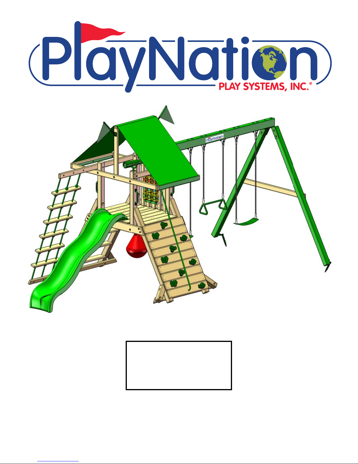
Latitude
Model: 1100
(BOXES: 1100-1, 1100-2, 1100
Swing Beam/Swing Leg Box, &
Slide Box)
Copyright © 2016 PlayNation Play Systems, Inc.
All Rights Reserved
*52-2024-T*
52-2024-T
190 Etowah Industrial Court
Canton, GA 30114
www.playnation.com
Page 2

Please inspect and inventory all parts immediately upon accepting delivery. Use the
inventory pages in the manual to make sure you have received all necessary parts.
The quickest method to get any parts that are missing or damaged is use our “Quick
Response Center” located at:
www.playnation.com/support
DO NOT RETURN THIS PRODUCT TO THE RETAILER OR CONTACT THE RETAILER DIRECTLY.
THE RETAILER DOES NOT STOCK COMPONENTS.
PLEASE RETAIN ALL INSTRUCTIONS FOR FUTURE REFERENCE. KEEP THEM IN A SAFE
PLACE WHERE YOU CAN REFER TO THEM AS NEEDED. CHECK FOR REVISED INSTRUCTIONS AT:
http://www.playnation.com/manuals.html
Page 3

PLAYNATION WARRANTY 2016
MANUFACTURER'S LIMITED LIFETIME WARRANTY
PlayNation Play Systems, Inc. warrants its Lifetime™ series of swing sets to be free from defects in
workmanship and materials, under normal use and conditions, for the lifetime of the product for above
ground structural wood components and for two years for all other components (e.g., swings, hardware,
plastics, tarps, rope ladder, etc.) except PlayNation's Super Scoop Slides™ and Super Tube Spiral Slides™.
PlayNation warrants its Super Scoop Slides™ and Super Tube Spiral Slides™ to be free from defects in
workmanship and materials, under normal use and conditions, for the lifetime of the product.
PlayNation warrants its Regal™, Imperial™, and Empire™ series swing sets to be free from defects in
workmanship and materials, under normal use and conditions, for a period of 15 years for above ground
structural wood components and for two years for all other components (e.g., swings, hardware,
plastics, tarps, rope ladder, etc.).
PlayNation warrants all remaining products, including but not limited to its Free Standing Swing Set, Free
Standing Tire Swing, See-Saw, Children's Picnic Table with Umbrella, Play-Zee-Bo™ and spring riders to
be free from defects in workmanship and materials, under normal use and conditions, for a period of 1
year. All accessories purchased separate from those included with one of our swing set packages have a
one year limited warranty.
Cosmetic imperfections and natural tendencies of wood such as peeling, splintering, warping,
seasonal checking or cracking, knots or knot holes, etc. are normal characteristics of all outdoor
wooden play equipment and are not covered by this warranty. Checks or cracks in wood components
that do not affect the intended function of the part, piece or overall swing set are not covered under
this warranty.
Wood rot or decay that develops because the product was installed in an area with poor drainage is not
covered under this warranty. Lumber that has been damaged by wood boring bees, or conditions that
develop as a result of faulty or improper installation of the product, are not covered by this warranty.
Fading of stain, discoloration or mold on any wood part or accessory is not covered by this warranty.
Cracks in plastic components, surface rust on hardware and chips on powder coated materials are not
considered defects in material as long as they do not affect the functionality or structural integrity of the
part or component.
It is the owner's responsibility to maintain the swing set. This includes but is not limited to staining and
sealing the lumber as needed and regular inspection to be sure all hardware is tight. Instructions for
proper maintenance can be found on PlayNation's website. Imperfections or conditions that develop
because of a failure to properly maintain the swing set are not covered by this warranty.
Page 4

PLAYNATION WARRANTY 2016
PlayNation will, at its discretion, replace any above ground part within the stated warranty period that is
defective in workmanship or materials. This decision is subject to verification of the defect, which, at
PlayNation's discretion, may be accomplished by submitting photographs or by delivery of the defective
part to PlayNation. PlayNation Play Systems, Inc. • 190 Etowah Industrial Ct. • Canton, GA 30114 •
770-704-9300 Monday to Friday 9AM-5PM EST. Any warranty claim must include proof of purchase,
including the date of purchase. In addition, within the first 30 days from the date of purchase,
PlayNation will replace any parts discovered to be missing from or damaged in the original packaging.
This warranty is valid only if the product is used for the purpose for which it was designed and installed
at a residential, single-family dwelling. This warranty is void if the product is used in a commercial,
institutional or multi-family setting. This warranty does not cover normal wear and tear or (a) products
that have been damaged by acts of God and/or nature, negligence, misuse or accident; (b) products
that have been modified or repaired by unauthorized persons; (c) the cost of labor; or (d) the cost of
shipping any replacement product or part.
PLAYNATION DISCLAIMS ALL OTHER REPRESENTATIONS AND WARRANTIES OF ANY KIND, EXPRESSED,
IMPLIED, STATUTORY OR OTHERWISE, INCLUDING THE IMPLIED WARRANTIES OF MERCHANTABILITY
AND FITNESS FOR A PARTICULAR PURPOSE. PLAYNATION WILL NOT BE LIABLE FOR ANY INCIDENTAL OR
CONSEQUENTIAL DAMAGES. This warranty is non-transferable and does not extend to the owners of the
product subsequent to the original purchaser. Some states do not allow limitations on implied
warranties or exclusion of incidental or consequential damages, so these restrictions may not be
applicable to you. This warranty gives you specific legal rights. You may also have other rights which vary
from state to state.
Page 5

IMPORTANT SAFETY GUIDELINES
This product is recommended for use by children ages 3-11. This product is intended for residential
use only and not intended for use in any public setting. A safety surface such as mulch or recycled
tire should be used under the play set to prevent injury from falls. Also a 6 foot safety zone should be
used around the entire play set.
As with any home project, good judgment and respect for power tools will greatly reduce the risk
of injury. PlayNation recommends you follow all tool manufacturers’ safety guidelines. Always wear
eye protection and safety gloves to prevent injury. In several phases of construction two people may
be required for lifting and securing of lumber. While the play set is being constructed, please keep
children off the equipment until the project is complete. Bolts and screw heads should be checked
regularly for tightness. The ground ladder, rope ladder, slide, swings and other areas where children
spend a majority of their playtime should be checked more frequently.
PlayNation shall not be liable for incidental, indirect or consequential damages or injuries that result
from the building and/or playing on our play sets. Adult supervision is recommended anytime a play
set is being used.
WEIGHT LIMITS FOR PLAYNATION PLAYSETS
• FORT PLATFORMS: 800 LBS. TOTAL WEIGHT
• SWING BELT: 225 LBS.
• TANDEM SWINGS: 70 LBS. PER CHILD. UP TO 140 LBS TOTAL WEIGHT.
• TRAPEZE: 125 LBS.
• FULL BUCKET SWING/ HALF BUCKET SWING: 50 LBS.
• HEAVY DUTY TODDLER BUCKET SWING: 85 LBS.
• INFANT SWING: 35 LBS.
• TIRE SWING: 125 LBS. TOTAL WEIGHT
• ROPE LADDER: 75 LBS.
• ROCK WALL: 150 LBS.
• CLIMBING RAMP: 150 LBS.
• MONKEY BARS: 175 LBS.
• ALL SLIDES: 150 LBS.
PlayNation recommends that the weight limits for all components must not be exceeded. Failure to
adhere to these and other safety guidelines could result in damage to the play set and injury to the
users.
Page 6

THIS PAGE INTENTIONALLY LEFT BLANK
Page 7
WARRANTY REGISTRATION
- LATITUDE -
PlayNaon manufactures the
nest quality products that
are designed for outstanding
strength and durability. We
back our products with an
unparalleled warranty. In the
unlikely event that you will need
to contact us about covered
repairs, we must have a valid
Warranty Registraon on le.
Where did you buy this product?:
Store Store City Store StateDate of
Purchase
OPTION 1
OPTION 2
OPTION 3
3 EASY WAYS TO REGISTER
Fax this completed form to:
(800) 880-3300
Complete the online registraon form at:
hp://www.playnaon.com/register
Scan this QR Code
with your smart
phone to complete
the form using your
OR
phone
Mail this completed form to:
PlayNaon Playsets
190 Etowah Industrial Court
Canton, GA 30114
Your registraon informaon:
Name: Email:
Address:
Street City State Zip
Please select
your age?
18-30
31-40
41-50
51+
How would
you rate the
quality of
this product?
How old are
your children?
2-3
4-5
6-7
8+
Would you recommend this product to friends & family?
Comments:
Excellent
Above Average
Average
Below Average
Poor
Yes No
Page 8

THIS PAGE INTENTIONALLY LEFT BLANK
Page 9

IMPORTANT – PLEASE READ
Congratulations! You have just purchase one of the finest residential wooden swing sets available today. As
with any wooden product that spends its entire life outside, in varying elements, it is important to know what to
expect with your new swing set so that your family can enjoy it for many years.
As your swing set acclimates to its new environment, natural characteristics of the wood can show in the form
of checks, or “cracks” in the lumber. In almost all cases this is normal and it will not affect the structural
integrity of your play set and is not covered under warranty.
KEEPING YOUR PLAYSET LIKE NEW
MUST DO’s
The following owner responsibilities are crucial to the safety, integrity and aesthetic appeal of your
swing set and may affect the warranty if not adhered to.
WITHIN 60 DAYS
Check and tighten Hex Bolts/T-nuts, Carriage Bolts/Lock-nuts, and Lag Screws within the first 60 days and
•
then twice annually – once before each season and then once during the season.
WITHIN 90 DAYS
• Apply a sealant or semi-transparent stain with sealant within the first 90 days of owning the swing set. If
applicable state laws allow, an oil based product will penetrate and protect the lumber better than a water
based product. Because climate conditions can vary drastically from region to region, we suggest asking the
product covering specialists at any number of specialty paint stores or home improvement centers for a
product that would work best for your local environment. ** TIP – while the set is new, take a small board from
your swing set to the store with you so they can color match the tint of the stain or sealant. Be sure to replace
the board when you get home.
SEASONAL REMINDERS
If your area experiences regular snowfall, remove your fabric tarp/canopy to avoid stretching, sagging or
•
tearing of the material. Store it inside, folded up, and it will be as good as new when winter is over.
If your area experiences extremely cold temperatures, remove swing belts and other pliable features to
•
prolong the lifespan of these play activities.
OTHER TIPS
Spray swing hangers with Pam, Mazola or olive oil to stop squeaking; do not use petroleum based products
•
such as WD-40 or motor oil.
To repel yellow jackets and wasps, use a cotton ball and dab interior wooden corners underneath the play set
•
deck with a liquid dish soap. Avoid using insecticides.
To speed up the slide wipe the center of slide with wax paper every 2 - 3 weeks.
•
For additional safety and maintenance guidelines, please visit our website.
Page 10

IMPORTANT DOCUMENTS
CUSTOMER MUST READ AND RETAIN
Please go to the following links and read important SAFETY information prior
to using your new play structure.
http://www.playnation.com/safety-and-maintenance.html
http://www.playnation.com/manuals.html (Click on your specific model)
http://www.playnation.com/warranty.html
NOTE: Your children’s safety is our #1 concern. Observing the following statements
and warnings reduces the likelihood of serious injury. Please review these safety rules
regularly with your children.
WARNING:
Children must NOT use this play set until it has been
completely assembled and inspected by an adult to
ensure it has been properly installed.
PlayNation Play Systems, Inc.
190 Etowah Industrial Court
Canton, GA. 30114
Page 11
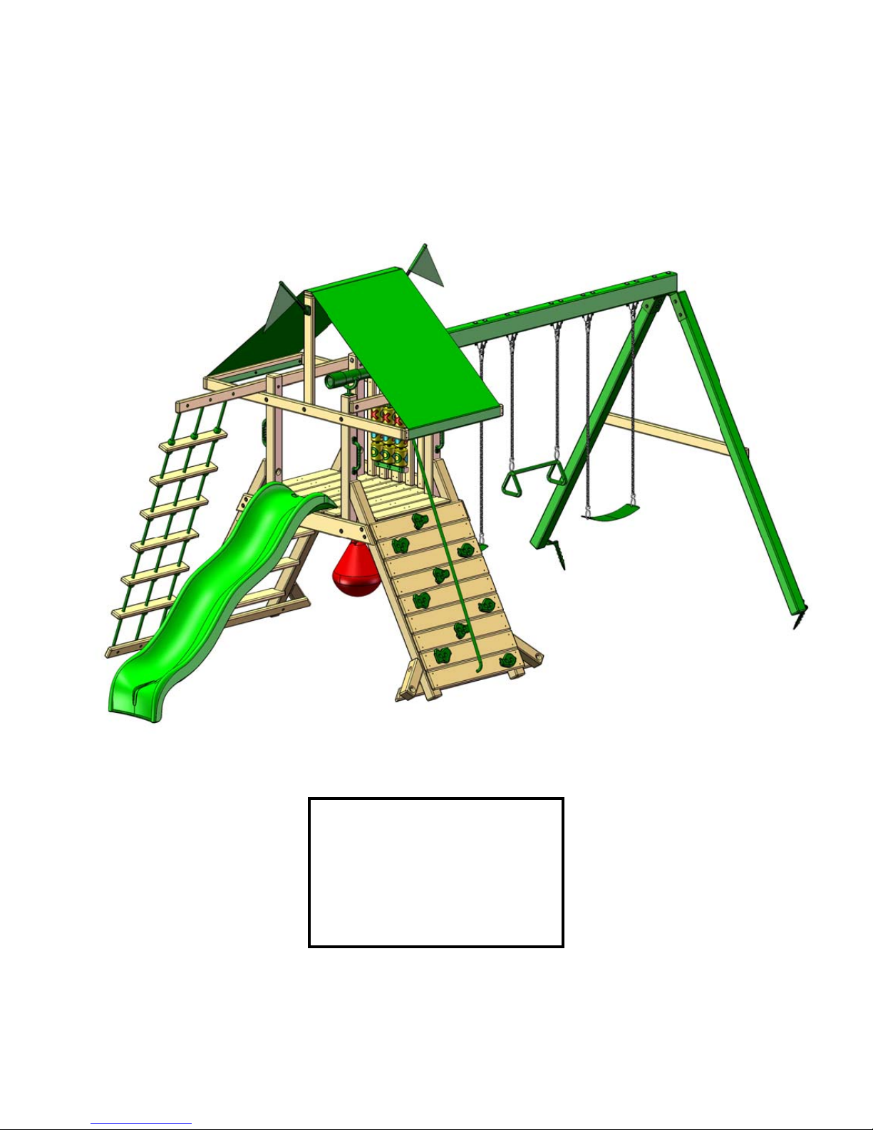
Model: 1100
(BOXES: 1100-1, 1100-2, 1100
Swing Beam/Swing Leg Box &
Slide Box)
REV: 2.29.2016
Page 12

TABLE OF CONTENTS
2
Safety Guidelines……………………………………….......…........................…...Pages 3-6
Leveling Fort, General Information and Denitions……….......…………............Pages 6-8
How to Install T-nuts, Board Identication, Predrill Lag Screw Directions and
Swing Beam Loading……....….........................................................................Pages 9-13
Site Plan, Required Tool List and Kit Contents…...…..………...…................ Pages 14-15
Hardware, Lumber and Accessory Checklists............................................... Pages 16-24
Ladder……………………………..………………………….......................……..... Steps 1-4
Rock Wall……………....……………….…………...….......................................... Steps 5-7
Outer and Inner Fort Supports………………………...…..……..……...…...…..... Steps 8-9
Corner Posts......................................................……………………...……...... Steps 10-11
Swing Beam Side Rail and Side Rails….……………………..……..............… Steps 12-14
Rope ladder Support and Rock Wall Rope Support…………….………................ Step 15
Leveling Play Set and Installing Lag Screws……………………………….............. Step 16
Rock Wall Boards, Tarp Boards and Deck Boards………………….…........... Steps 17-19
Rear Bottom Panel Board, Center Posts and Center Tarp Board....……....... Steps 20-22
Panel Slats and Center Deck Support……………………….…….……........... Steps 23-25
Swing Beam Assembly…………………………………......………..…….......... Steps 26-32
Rock Wall Rocks, Climbing Rope and Rope Ladder..........................…......... Steps 33-35
Mounting Slide…………………………………………………………........................ Step 36
Attaching Tarp…………....……………………........................................................ Step 37
Telescope, Safety Handles and Hanging Swings…………..….……….....…... Steps 38-40
Punching Ball and Tic Tac Toe........................................................................ Steps 41-42
Flag Kit and Name Plate........................................................................................ Step 43
Ground Stakes....................................................................................................... Step 44
PLEASE READ OWNER’S MANUAL CAREFULLY
BEFORE STARTING ASSEMBLY!
Page 13

Safety and Maintenance Tips for Your New Play Set:
3
NOTE: Your children’s safety is our #1 concern. Observing the
following statements and warnings reduces the likelihood of serious
or fatal injury. Please review these safety rules regularly with your
children.
• This play set is designed for the use of 4 occupants who have a combined weight not
exceeding 800 pounds on the elevated oor, 3 occupants who have a combined weight
of 425 pounds on the swing area, for a total Unit capacity of 7 occupants who have a
combined weight of 1225. (This weight does not include any picnic table area(s).)
• On-site adult supervision is required.
• Teach children not to walk close to, in front of, behind, or between moving swings or
other moving playground equipment.
• Teach children to sit in and never stand on swings
• Teach children not to twist the chains and ropes and not to loop them over the swing
beam, since this may reduce the strength of the chain or rope.
• Teach children not to jump from swings or other playground equipment in motion.
• Teach children not to push empty seats. The seat may hit them and cause serious
injury.
• Teach children to sit in the center of the swings with their full weight on the seats.
• Teach children not to use the equipment in a manner other than intended.
• Teach children to always go down slides feet rst. Never slide headrst.
• Teach children to look before they slide to make sure no one is at the bottom.
• Teach children to never run up a slide, as this increases their chances of falling.
• The parents should have the children dress appropriately with well-tting shoes. Loose
clothing such as scarves and ponchos should not be worn. Always take off, tie up or
tuck in cords and drawstrings on children’s clothing. These things can get caught on
playground equipment and strangle a child.
• Teach children not to climb when the equipment is wet.
• Teach children to never jump from a fort deck. They should always use the ladder,
ramp or slide.
• Teach children to never crawl or walk across the top of monkey bars or swing beam.
• Teach children to never crawl on top of a fort roof or on the outside of a tube slide.
• Verify that any suspended climbing ropes, chains, or cables are secured at both ends
and that they cannot be looped around an adult hand.
• Teach children not to attach items to the playground equipment that are not specically
designed for use with the equipment, such as, but not limited to, jump ropes, clothesline,
pet leashes, cables and chain as they may cause a strangulation hazard.
• Teach children to never wrap their legs around swing chain.
• Teach children to never slide down the swing chain.
• Teach children to remove their bike or other sports helmet before playing on the
playgound equipment.
• Teach children to NEVER look at the sun or other bright light through any accessory
such as but not limited to a telescope, periscope or binoculars.
WARNING: Children must NOT use this play set until it has been
completely assembled and inspected by an adult to insure it has been
properly installed and the swing beam legs are anchored.
Page 14

Safety and Maintenance Tips for Your New Play Set:
4
(continued)
Playgrounds should be inspected on a regular basis. If any of the following conditions are noted,
they should be removed, corrected, or repaired immediately to prevent injuries.
• Hardware that is loose, worn or that has protrusions or projections.
• Exposed equipment footings.
• Scattered debris, litter, rocks, or tree roots.
• Splinters, large cracks, and decayed wood components.
• Deterioration and corrosion on structural components, which connect to the ground.
• Missing or damaged equipment components, such as handholds, guardrails, swing seats.
• Check all nuts and bolts twice monthly during the usage season and tighten as required.
(But not so tight that you crack the wood) We recommend you check the swing beam and
hardware often due to wood expansion and contraction. It is particularly important that this
procedure be followed at the beginning of each season.
• Remove plastic swing seats and take indoors or do not use when the temperature drops below
32°F. Reinstall swings and other swing equipment at the beginning of the usage season.
• Oil all metallic moving parts monthly during the usage period.
• Check all coverings for bolts and sharp edges twice monthly during usage season to be certain
they are in place. Replace when necessary. It is especially important to do this at the beginning
of each new season.
• Check swing seats, ropes, cables and chains monthly during usage season for evidence of
deterioration. Replacement should be made of any swing seat that has developed cracks in the
plastic seats. Ropes, cables and chains should be removed and replaced if excessive wear is
found. Contact us for warranted replacement parts.
• Swing chains, rings, ropes, etcetera should always be fastened to a rotating swing hanger.
NEVER attach a chain, ring, rope, etcetera to a stationary hanger such as but not limited to an
eye bolt. Severe wear could occur leading to an injury.
• For rusted areas on metallic members such as monkey bars, hand supports brackets, etc.;
sand and repaint, using a non lead-based paint meeting the requirements of Title 16 C.F.R. Part
1303. These requirements are available at: http://www.cpsc.gov/
• Inspect wood parts monthly. The grain of the wood sometimes will lift in the dry season
causing splinters to appear. Light sanding may be necessary to maintain a safe playing
environment. If you are treating your play set with stain regularly, it will help prevent severe
checking/splitting and other weather damage.
• Once or twice a year, depending on your climate conditions, you must apply some type of
protection (sealant) to the wood of your unit. Prior to the application of sealant, lightly sand any
“rough” spots on your set. Please note this is a requirement of your warranty.
• Creating and maintaining the play set on a level location is very important. As your children
play, your play set will slowly dig its way into the soil, and it is very important that it settles
evenly. Make sure the play set is level and true once each year or at the beginning of each play
season.
• Twice a month during the usage season rake the playground protective surfacing materials to
prevent compaction and maintain appropriate depths. Replace the protective surfacing materials
as required.
• Disposal Instructions: When the play set is no longer desired, it should be disassembled and
disposed of in such away that no unreasonable hazards will exist at the time the play set is
discarded.
Page 15

Play Set Surfacing Recommendations:
5
Below are some of the recommendations that the U.S. Consumer Product Safety
Commission (CPSC) offers from its Handbook for Public Playground Safety. The guide
can be downloaded in full at www.cpsc.gov/cpscpub/pubs/325.pdf
1. Protective Surfacing - Since almost 60% of all injuries are caused by falls to the
ground, protective surfacing under and around all playground equipment is the most
critical safety factor on playgrounds.
Certain manufactured synthetic surfaces also are acceptable; however, test data on
shock absorbing performance should be requested from the manufacturer.
Asphalt and concrete are unacceptable. They do not have any shock absorbing
properties. Similarly, grass and turf should not be used. Their ability to absorb shock
during a fall can be reduced considerably through wear and environmental conditions.
Certain loose-ll surfacing materials are acceptable. Surfacing materials are acceptable,
such as the types and depths shown in the table.
Fall Heights and Materials
Type Of Material 6 in. depth 9 in. depth 12 in. depth
Double-Shredded bark mulch 6’ Fall Height 10’ Fall Height 11’ Fall Height
Wood Chips 6’ Fall Height 7’ Fall Height 12’ Fall Height
Fine Sand 5’ Fall Height 5’ Fall Height 9’ Fall Height
Shredded Tires* 10-12’ Fall Height N/A N/A
Fine Gravel 6’ Fall Height 7’ Fall Height 10’ Fall Height
*This data is from tests conducted by independent testing laboratories on a 6-inch depth of uncompressed shredded tire samples
produced by four manufacturers. The tests reported critical heights, which varied from 10 feet to greater than 12 feet. It is
recommended that persons seeking to install shredded tires as a protective surface request test data from the supplier showing the
critical height of the material when it was tested in accordance with ASTM F1292.
It should be recognized that all injuries due to falls cannot be prevented no matter what
surfacing material is used.
Page 16
2. Fall Zones - A fall zone, covered with a protective surfacing material, is essential
6
under and around equipment where a child might fall. This area should be free of other
equipment and obstacles onto which a child might fall. Stationary climbing equipment
and slides should have a fall zone extending a Minimum of 6’ in all directions from the
perimeter of the equipment.
Swings should have a fall zone extending a minimum of 6’ from the outer edge of the
support structure on each side. The fall zone in front and back of the swing should
extend out a minimum distance of twice the height of the swing as measured from the
ground to the top of the swing support structure.
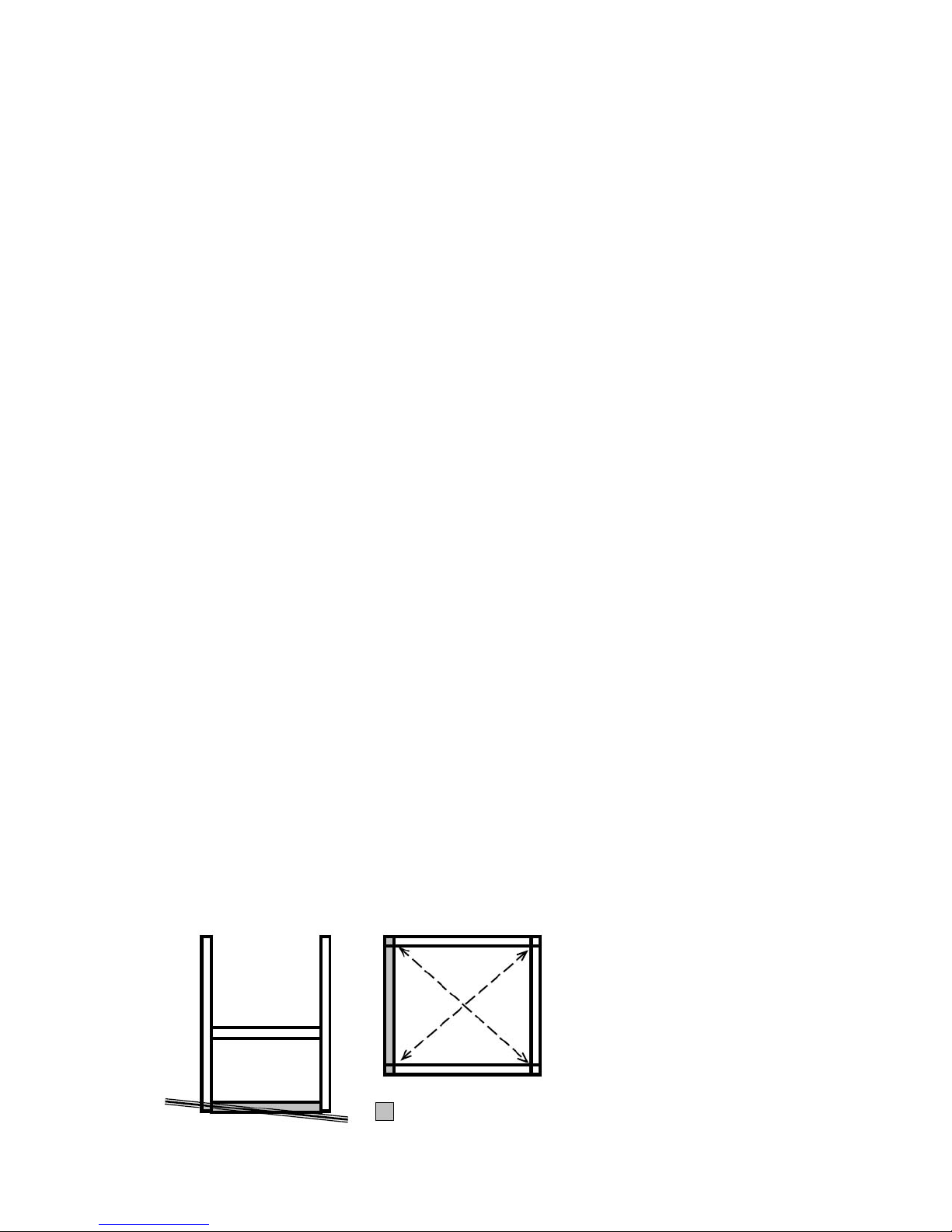
LEVELING YOUR FORT DURING ASSEMBLY
• Complete the steps which will be the basic frame of the fort. {i.e. four corner posts with
base (sand box boards) and deck supports}
• Position in the most level area chosen for the play set, keeping in mind the location
and size of the swing beam, ladder, slides, etc. that extend off the fort.
• Once the frame is in the nal position, check for vertical and horizontal levelness to
determine which side(s) will need to be dug into the ground to level the play set.
• With a shovel, score the ground around the outside edges of the sandbox boards on
the ‘high’ side of the fort. This is the area that will be dug in. Make sure to score deep
enough; the scored lines will be your digging template.
• Push the frame off and away from the scored area, far enough to dig and remove dirt
to reach the appropriate depth.
• Dig a channel along the scored line(s) for the base of the fort (corner post and
sandbox boards) to rest into. Dig the channel(s) to the same level depth. The bottom
of the channel(s) should be level to each other so your frame doesn’t teeter or rock
because the channel(s) are uneven.
• Once you have removed enough grass and dirt, slide/push the frame into the
channel(s). Place a level on the vertical and horizontal boards of the frame to determine
if enough soil, or too much, was removed.
• Repeat this process until the basic frame is plumb and level and in its nal position
before completing the rest of the assembly.
• Measure to make sure fort is square.
Important: if you require a channel depth of more than 6”, then we
recommend you have your play set area professionally graded before
completing assembly.
Example Play area:
Side View of
Playset Frame
(Grade is the
Slanted Line)
The diagonal measurements should be the
same from corner post to
corner post. If not, adjust
corner posts so that the
distance is equal.
= Area to be scored and
channeled for levelness
Page 17

General Info to Review Before Installation
7
• Depending on your experience, assembly of the playset can take as little as 6 hours
up to 24 hours, depending on size, after inventory of parts; therefore, we recommend
you set aside a full two days for assembly.
• Identify all of the parts for your play set. Empty each box and lay out boards so you
can see each part. Your instruction book will have detailed drawings that will make it
easy for you to recognize individual parts. Keep all hardware and metal parts separate
from wooden pieces.
• After everything is laid out, check carefully to ensure all parts are present. Make sure
there are no broken boards.
• Find an area to sort your hardware. It is best to open the hardware on a solid surface
so that you do not lose any pieces in the grass. This will save time and familiarize you
with all the different pieces in the hardware bag.
• Important note: Wood has some natural defects such as knots, surface cracks, etc…
We reject parts that are structurally defective. We use a high quality lumber in our
structures; however, you should inspect each part for splinters or rough spots and sand
them smooth to prevent injury.
• After familiarizing yourself with all of the components, read all instructions thoroughly.
Reading instructions after you have studied the parts will help you understand the
installation process, and help to eliminate unnecessary mistakes.
• Pay close attention to the diameter and length of each bolt and screw.
• Never tighten hardware completely at rst. It helps to have some adjustment for bolt
alignment while you are attaching parts together. After everything is square, tighten
each joint.
• After the main unit is assembled it is critical that the oor is level and square. If the
main frame is not level, the walls and oor will be out of square.
• After you complete installation, make sure every bolt, screw, and nut is tight, and every
board is secure. Wood will expand and contract with the seasons.
• Place the set on level ground, not less than 6 feet from any structure or obstruction
such as a fence, garage, house, overhanging branches, laundry lines, or electrical
wires.
Page 18
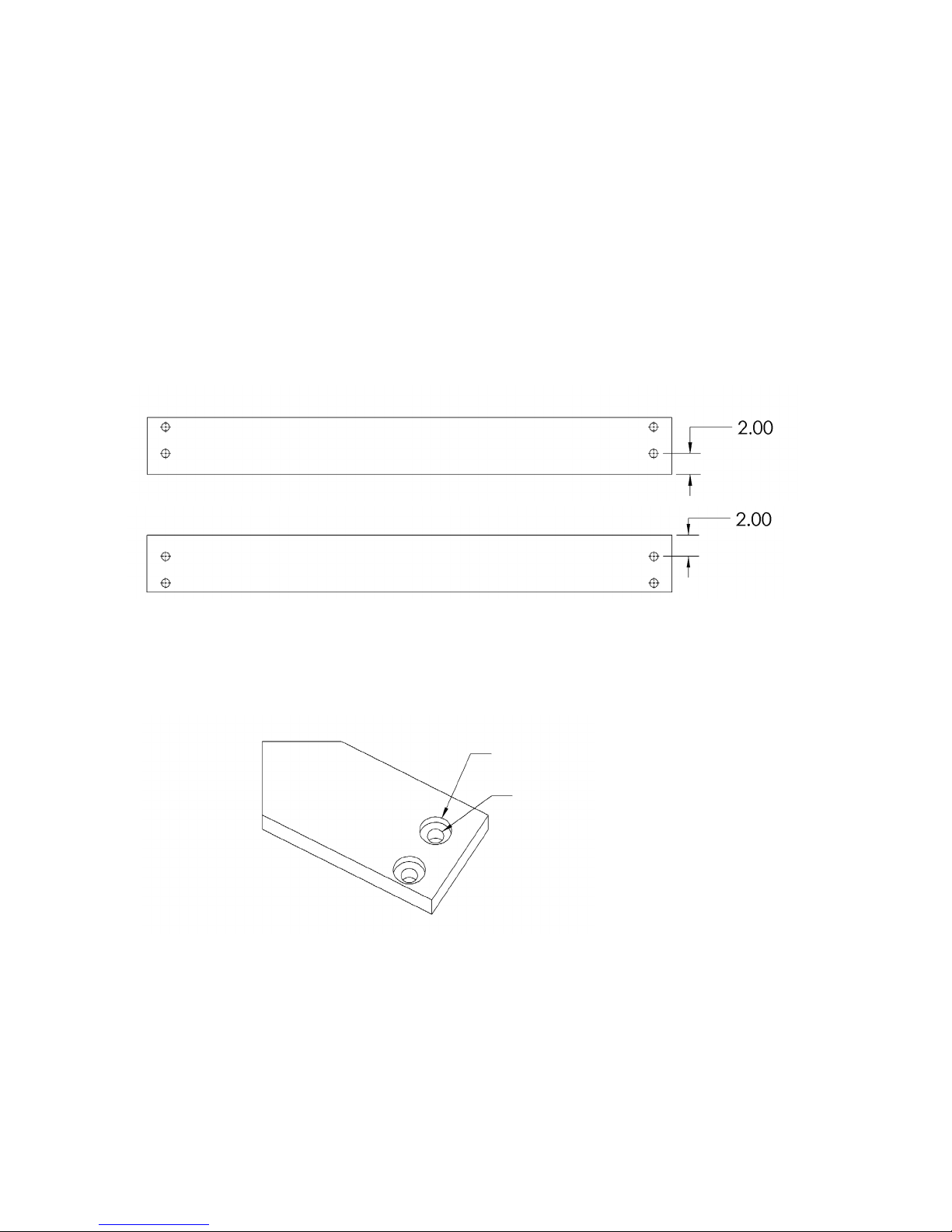
This page is a list of denitions and explanations used throughout our
8
instructions to aid you in the assembly of your play set.
Offset Holes- Throughout the installation procedures we will refer to parts with offset
holes. This refers to the orientation of the holes on the board. An offset hole is one that
is closer to one side than it is the other or in other words, it is not centered on the board.
In the procedures you will be instructed to attach the boards with the holes offset up or
with the holes offset down. This refers to which side of the board the hole/holes should
be closer to. Offset holes up= hole/holes will be closer to the top of the board. Offset
holes down= hole/holes will be closer to the bottom of the board. Note: some parts do
not have offset holes, but instead the holes are on center. Therefore there will not be
any reference on how to offset these parts.
EXAMPLE OF OFFSET HOLES UP
EXAMPLE OF OFFSET HOLES DOWN
Counter-sunk holes - Many of the parts that will be used have counter-sunk holes. A
counter-sunk hole is one that surrounds one side of a through hole, but does not extend
through the wood it’s self. When using a counter-sunk hole the bolt will be inserted
through the through hole and either the head of the bolt and washer or nut and washer
will occupy the counter sunk hole.
Counter-Sunk Hole
Through Hole
Lag Screws- Lag screws are used in the construction of our play sets to enhance
the structural integrity of the unit. There will not be predrilled holes in the post for lag
screw installation. Lag screws are self-tapping, though if you are using a manual socket
wrench it may be advantageous to pre-drill a hole rst. Instructions for this are provided
on a separate page in the front of the manual. Be sure to tighten the lags completely
when driving them in by hand. Power tools such as a heavy duty impact driver or large
power drill should have enough torque to drive in the lag screws, but make sure not to
over tighten as this can cause the threads to “strip out” in the post.
Page 19
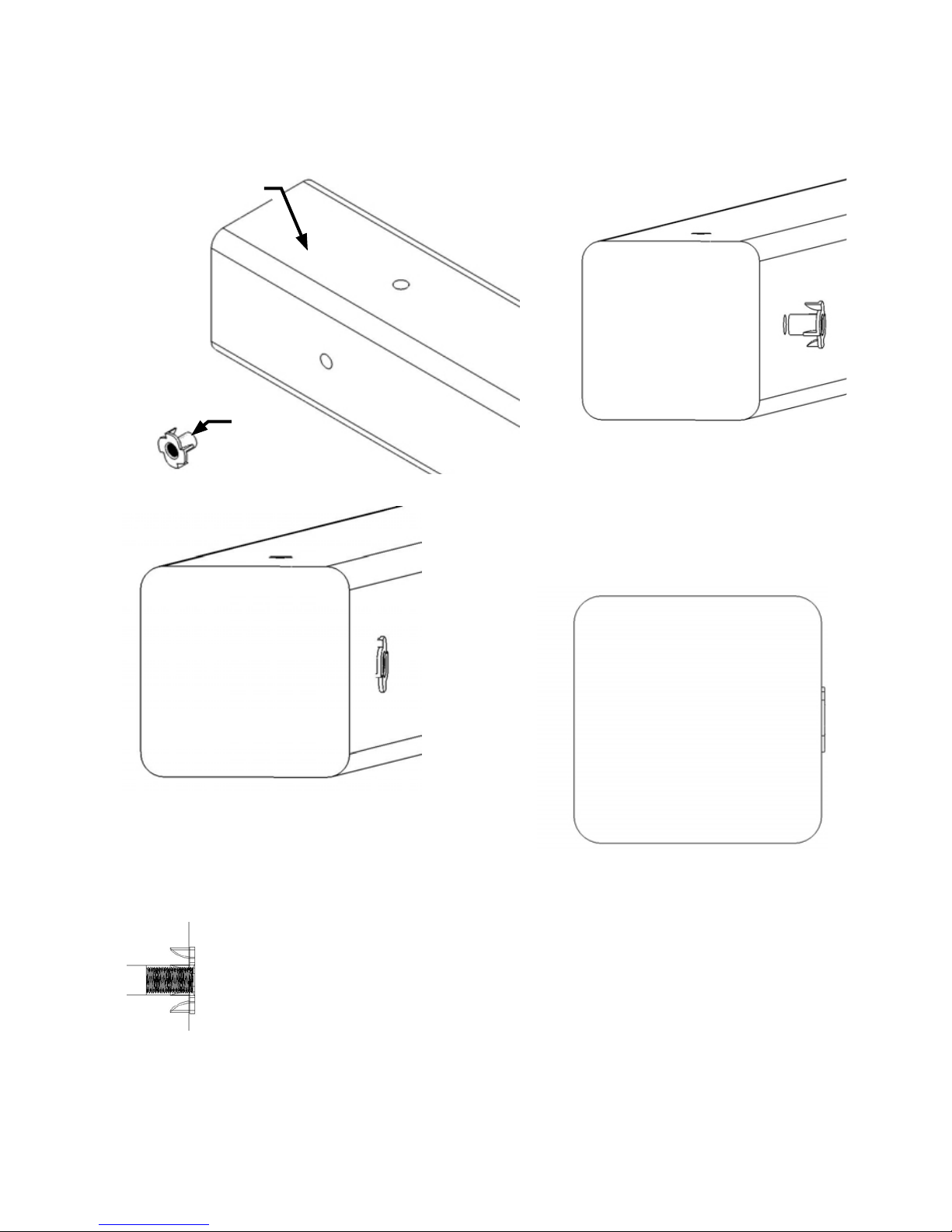
Common Installation Practice Installing T-nuts
9
When installing T-nuts into the wood, use a smooth faced hammer to set the face of the
T-nut ush into the wood.
Corner Post
T-nut
Insert the barrel of the T-nut into the
predrilled hole. Using a smooth faced
hammer, drive the T-nut until the face
of the T-nut is ush to the wood.
This picture shows the T-nut inserted
and installed ush to the wood.
Flush (Correct)
Cross Section end view, you are looking at an X-ray view
of the post and T-nut. The barrel of the T-nut is in the
corner post the line is the face of the wood.
This picture shows an end view of the T-nut
installed ush to the wood.
WARNING: DO NOT EMBED THE TOP
OF THE T-NUT INTO THE
FACE OF THE WOOD
Page 20
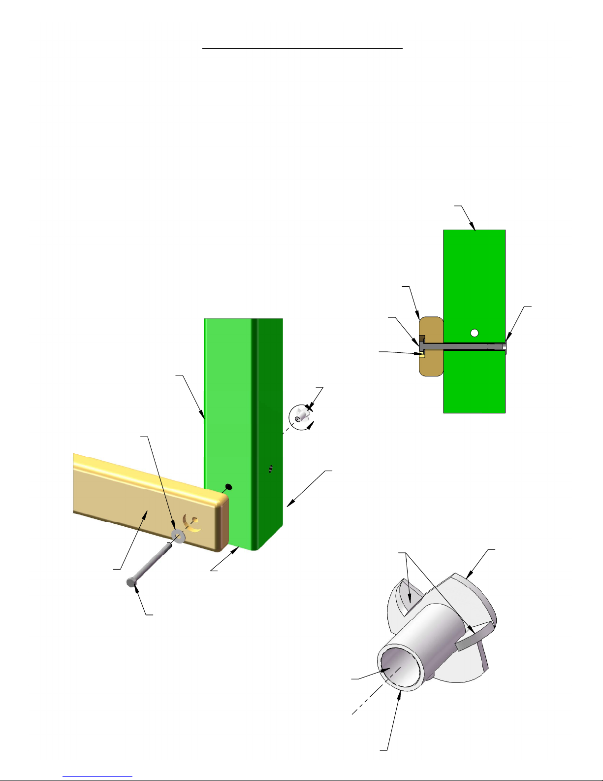
HOW A T-NUT WORKS
10
THE FIRST STEP IN OUR ASSEMBLY INSTRUCTIONS IS TO INSERT T-NUTS INTO THE CORNER
POSTS. A T-NUT IS A FASTENER WHICH IS THREADED ON THE INSIDE AND IT FUNCTIONS
JUST LIKE A STANDARD HEX NUT. YOU INSERT THE T-NUTS INTO THE PREDRILLED HOLES IN
THE CORNER POSTS.
THE T-NUT HAS A BARREL SHAPED END WHICH GOES INTO THE HOLE IN THE CORNER POST.
THE T-NUT ALSO HAS AN FLANGE SHAPED END WITH TEETH. THE TEETH PENETRATE INTO THE
CORNER POST WOOD TO PREVENT THE T-NUT FROM SPINNING WHEN YOU TIGHTEN THE
HEX HEAD BOLT.
SHOWN BELOW YOU WILL SEE THE T-NUT IS HAMMERED INTO THE CORNER POST ON THE
BACK SIDE. THE BOARD IS BEING ATTACHED ON THE FRONT SIDE OF THE CORNER POST.
CORNER POST
BOARD YOU
ARE ATTACHING
TO CORNER POST.
HEX HEAD BOLT
T-NUT
FLANGE
IS HERE.
WASHER
BOARD YOU ARE
ATTACHING TO
CORNER POST.
CORNER POST
HEX HEAD BOLT
FRONT SIDE OF
CORNER POST
T-NUT
WASHER
A
BACK SIDE OF
CORNER POST
TEETH
CROSS SECTION VIEW
OF BOARD, CORNER
POST AND FASTENERS.
T-NUT DETAILS
FLANGE
SHAPED END
WITH TEETH
THREADS ON
INSIDE OF
BARREL .
BARREL
SHAPED
END GOES
INTO HOLE IN
CORNER POST.
DETAIL A
SCALE 2 : 1
Page 21
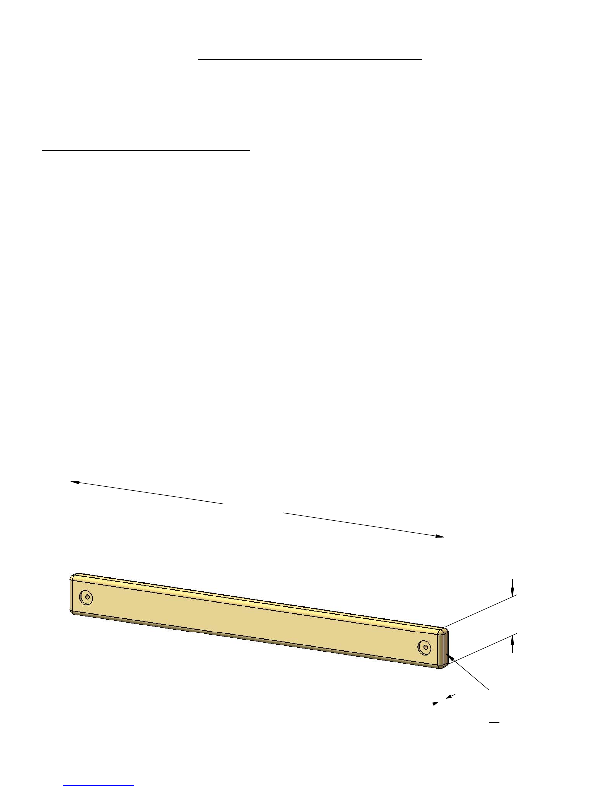
BOARD IDENTIFICATION
11
1. On the end of each board there should be a small white tag that is stapled or stuck into
place. Remove the staples and/or tag after the board is installed.
2. This white identifcation tag displays the thickness, width, length and an abbreviated
description of the part.
Example: a tag reads "2-4-3600-BPB"
The 2 is the thickness of the board. "Nominal Lumber" at a home center will measure 1-•
1/2" for the thickness. We "remill" that lumber to 1-3/8" thick.
The 4 is the width of the board. "Nominal Lumber" at a home center will measure 3-•
1/2" for the width. We "remill" that lumber to 3-3/8" wide.
Note: sometimes the width will be smaller than 3-3/8" because:
A) We need the width of the part to fit into a certain area of the play set.
B) We need the designation to be simple.
The 3600 is the length of the board. It means the board is 36 inches long. If the code •
were 3625 then the board is 36-1/4" in length.
The "BPB" abbreviation stands for "Bottom Panel Board". The wood part bill of materials •
in the instructions has a description which will match the abbreviation closely.
In the event that there is no tag on a wood part measure the part then:•
A)Use the measurements and compare them to the wood list at the front of the
instructions to identify it.
B)Look at the holes on the wood part and compare them to the pictures in the wood
list.
C)Look to see if the holes are centered or if they are offset up or offset down.
This should help you identify any parts that have missing tags. In the event that you
cannot identify a board please email us for assistance.
36" LENGTH
3
" WIDTH
3
8
3
"
1
8
THICKNESS
TAG
2-4-3600-BPB
Page 22
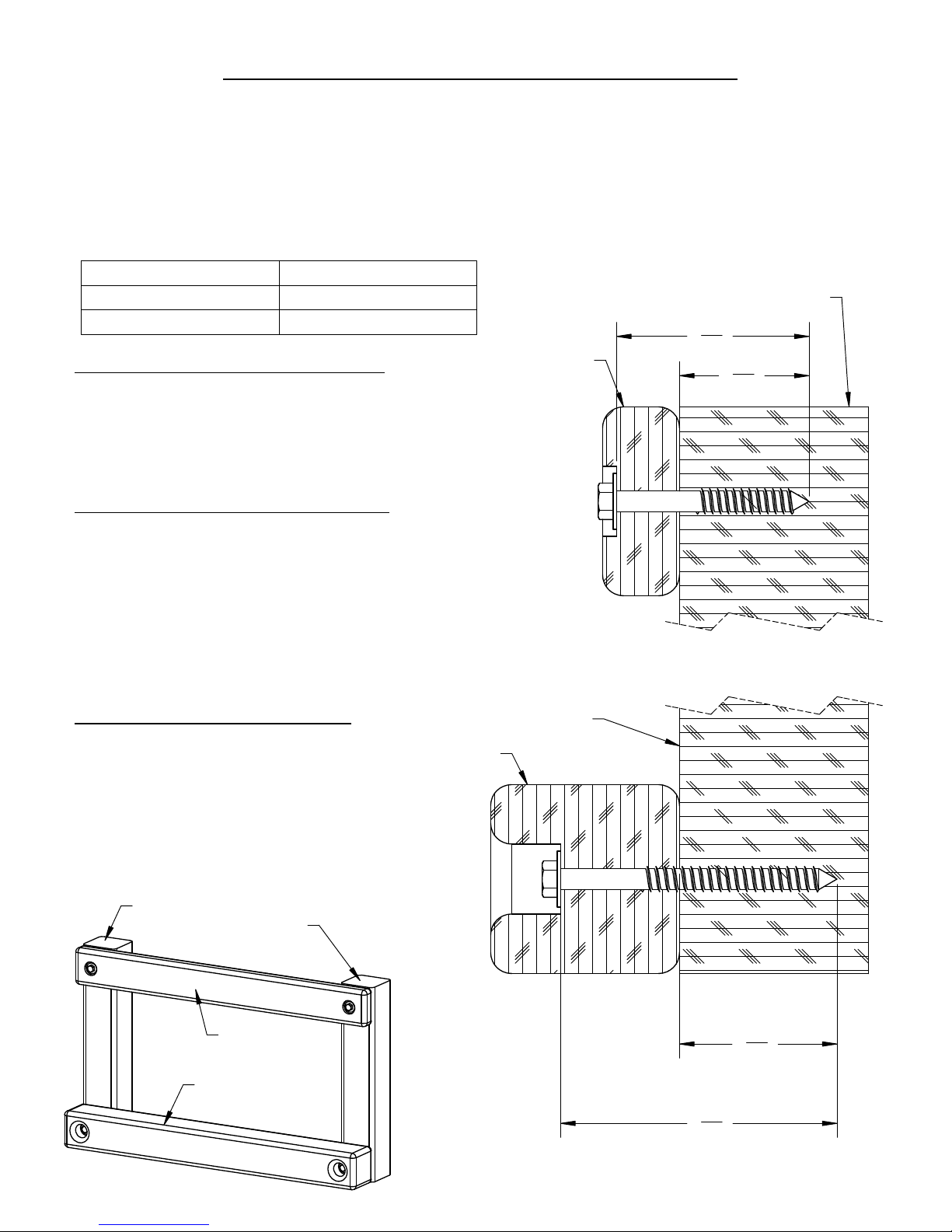
PRE-DRILL LAG SCREW DIRECTIONS
Pre-drilling holes for lag screws will make it easier to drive the screws in by hand.
12
"Jobber" length drill bits are available in sizes that are longer than standard drill bits and
those are ideal for the job. When using the drill bit you will have to "spot" drill the post
and then remove the board you are attaching to finish drilling the hole.
Pay attention to the DIAMETER of the lag screw you are installing. Your playset may
come with two different diameter lag screws. Each diameter will require a different size
drill bit. When installing lag screws DO NOT OVERTIGHTEN.
LAG SCREW DIAMETER DRILL BIT SIZE
7
16
2
" 3
16
Corner Post
5
"
5/16" DIAMETER 9/64"
3/8" DIAMETER 11/64"
Example: 3/8" diameter x 3-1/2" lag screw
This would be like the 2 x 4 board installation shown
below. Place the board into position. Spot Drill through
the holes in the 2 x 4 board into the corner posts with
an 11/64" drill bit. Remove the 2 x 4 board. Continue
to drill the holes to a total depth of 2-5/16" as shown at
the right. Install the 2 x 4 board.
Example 5/16" diameter x 3-1/2" lag screw
This would be like the 2 x 4 board installation shown
below. Place the board into position. Spot Drill through
the holes in the 2 x 4 board into the corner posts with
an 9/64" drill bit. Remove the 2 x 4 board. Continue to
drill the holes to a total depth of 2-5/16" as shown at
the right. Install the 2 x 4 board.
2 x 4 board
Example 3/8" diameter x 5" lag screw
This would be like the 4 x 4 board
installation shown below. Place the
board into position. Spot drill through the
holes in the 4 x 4 board into the corner
posts with an 11/64" drill bit. Remove the
4 x 4 board. Continue to drill the holes to
a total depth of 2-13/16" as shown at the
right. Install the 4 x 4 board.
Corner Post
Corner post
2 x 4 board
4 x 4 board
4 x 4 board
Corner Post
15
4 "
16
2
13
16
"
Page 23
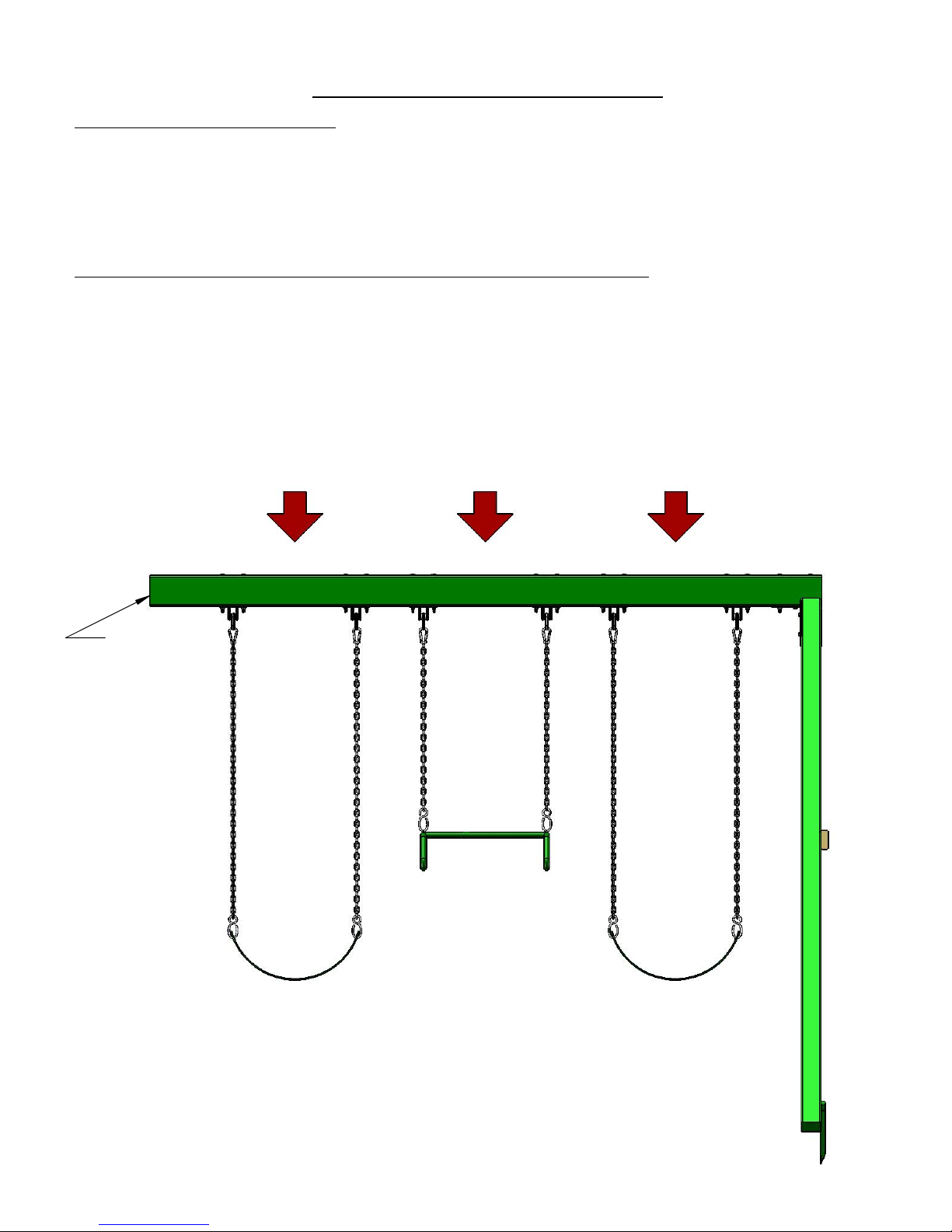
SWING BEAM LOADING
Weight Limits for Accessories:
13
The weight limit for a Swing Belt is 225 lbs. (Although 150lbs is the maximum recommended
swinging weight capacity for the swing position.)
The weight limit for a Trapeze Bar is 125 lbs.
Maximum Allowable swinging weight for a three position swing:
1) The maximum allowable swinging weight at each Swing Belt position is 150 lbs.
2) The maximum allowable swinging weight at the Trapeze position is 125 lbs.
3) The MAXIMUM SWING BEAM LOAD IS 425 lbs.
MAXIMUM SWING BEAM LOAD IS 425 LBS.
THIS END
OF SWING
BEAM IS
ATTACHED
TO PLAY SET.
SWINGING WEIGHT
125 LBS MAX150 LBS MAX
SWINGING WEIGHT
TRAPEZE BAR
150 LBS MAX
SWINGING WEIGHT
SWING BELT SWING BELT
Page 24
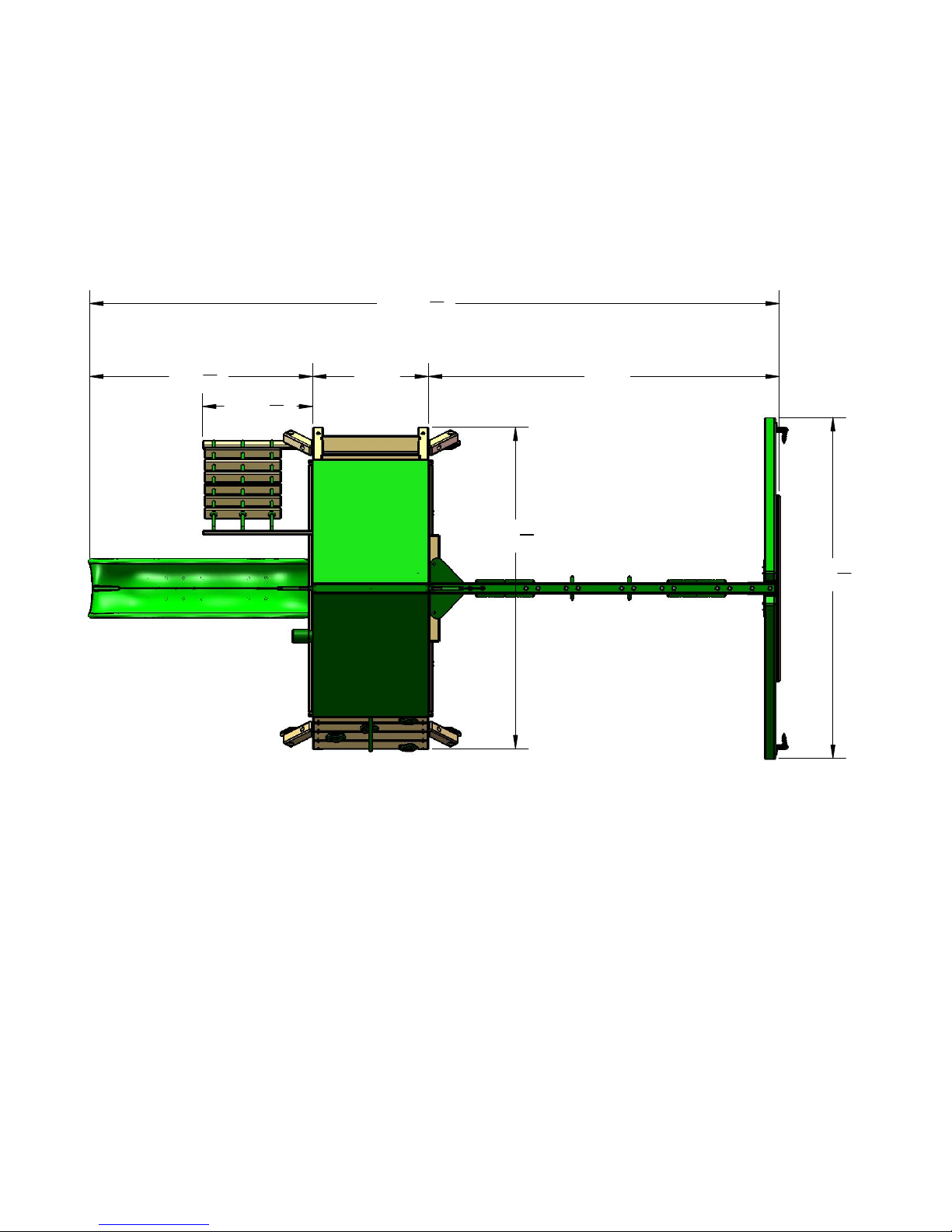
Please familiarize yourself with the manual, parts/components and general
14
construction process of your new playset before getting started.
SITE PLAN:
1
5'-9
4
"
2'-10
Rope
Ladder
Wiki Wave Slide
17'-10
3'-0"
1
"
4
Ladder
1
"
4
9'-1"
8'-37"
8
Trapeze Arm (1)
8'-9
7
"
8
Swing
Belts (2)
Rock Wall
Playset height: 9 feet
Swing Beam Height: 7 feet - 2 inches
Approximate assembly time: 6 to 10 hours
(6) foot unobstructed safety perimeter around playset recommended
Page 25

REQUIRED TOOL LIST:
15
___ Standard or Cordless Drill w/ Phillips Bit (#2 square bit provided)
___ 1/16”, 1/8”, 9/64”, 11/64” and 3/8” Drill Bits
___ ½” Wrench and Socket
___ ½” Deep Well Socket
___ 9/16” Deep Well Socket
___ 9/16” Wrench and Socket
___ Level
___ Tape Measure
___ Extension Cord (if using standard drill)
___ Hammer
___ Pencil
___ Locking Pliers (Vise Grips)
___ Shovel
___ Tape or Pen
KIT CONTENTS
Swings, Slides, Accessories:
___ (Qty ) Description
___ (2) Swingbelt w/ Chains
___ (1) 8ft. Wiki Wave Slide
___ (10) Rock Wall Grips (assorted colors and sizes)
___ (1) Trapeze Swing w/Chains
___ (1) Telescope
___ (1) Punching Ball
___ (4) Plastic Safety Handles
___ (1) Tic Tac Toe Panel
___ (1) 36” x 117” Tarp (Canopy)
___ (2) Flags
___ (2) Ground Stakes
Fort Hardware:
see following pages
Swing Beam Hardware:
see following pages
Wood Components:
see following pages
Page 26
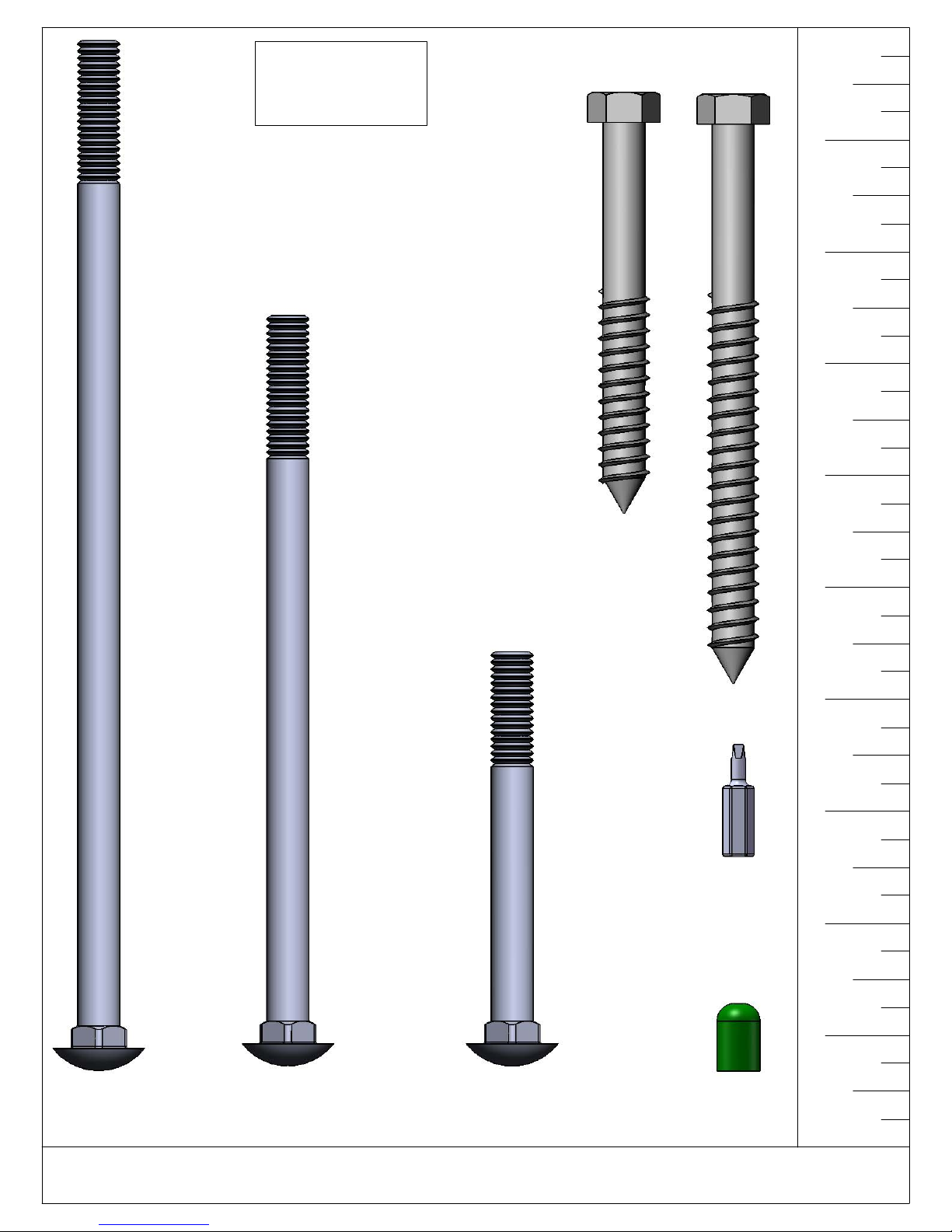
1100 HARDWARE
16
SHEET 1 OF 2
REVISION: C
9/16/2015 J.H.
3/8 X 3-1/2"
HEX LAG SCREW
QTY: 30
3/8" x 5"
HEX LAG
SCREW
QTY: 4
9
8
7
6
#2 SQUARE
DRIVE BIT
QTY: 1
5
4
3
2
1
3/8 x 9"
CARRIAGE BOLT
QTY: 1
3/8 x 6-1/2"
CARRIAGE BOLT
QTY: 16
USE THE RULER TO THE RIGHT TO MEASURE YOUR BOLTS AND SCREWS. PICTURE VIEWS SHOWN
ABOVE ARE 1:1 SCALE AND CAN BE USED TO MATCH BOLT AND SCREW SIZES.
3/8 x 3-1/2"
CARRIAGE BOLT
QTY: 4
PLASTIC
BOLT CAP
QTY: 21
Page 27

1100 HARDWARE
17
SHEET 2 OF 2
REVISION: C
9/16/2015 J.H.
9
#14 X 1-1/4"
PAN HEAD SCREW
QTY: 9
#8 X 1-1/4"
WOOD SCREW
QTY: 2
#8 X 2"
WOOD SCREW
QTY: 92
#8 X 2-1/2"
WOOD SCREW
QTY: 32
#10 X 3-1/2"
WOOD SCREW
QTY: 16
8
7
6
5
5/16" TEE NUT
QTY: 32
5/16 X 4-1/2"
HEX BOLT
QTY: 24
5/16 X 3-1/2"
HEX BOLT
QTY: 4
5/16 X 2-1/2"
HEX BOLT
QTY: 2
TORQUE WASHER
QTY: 19
1/4"
WASHER
QTY: 6
3/8" LOCK NUT
QTY: 21
3/8" WASHER
QTY: 57
5/16" WASHER
QTY: 38
4
3
2
1
USE THE RULER TO THE RIGHT TO MEASURE YOUR BOLTS AND SCREWS. PICTURE VIEWS SHOWN
ABOVE ARE 1:1 SCALE AND CAN BE USED TO MATCH BOLT AND SCREW SIZES.
Page 28
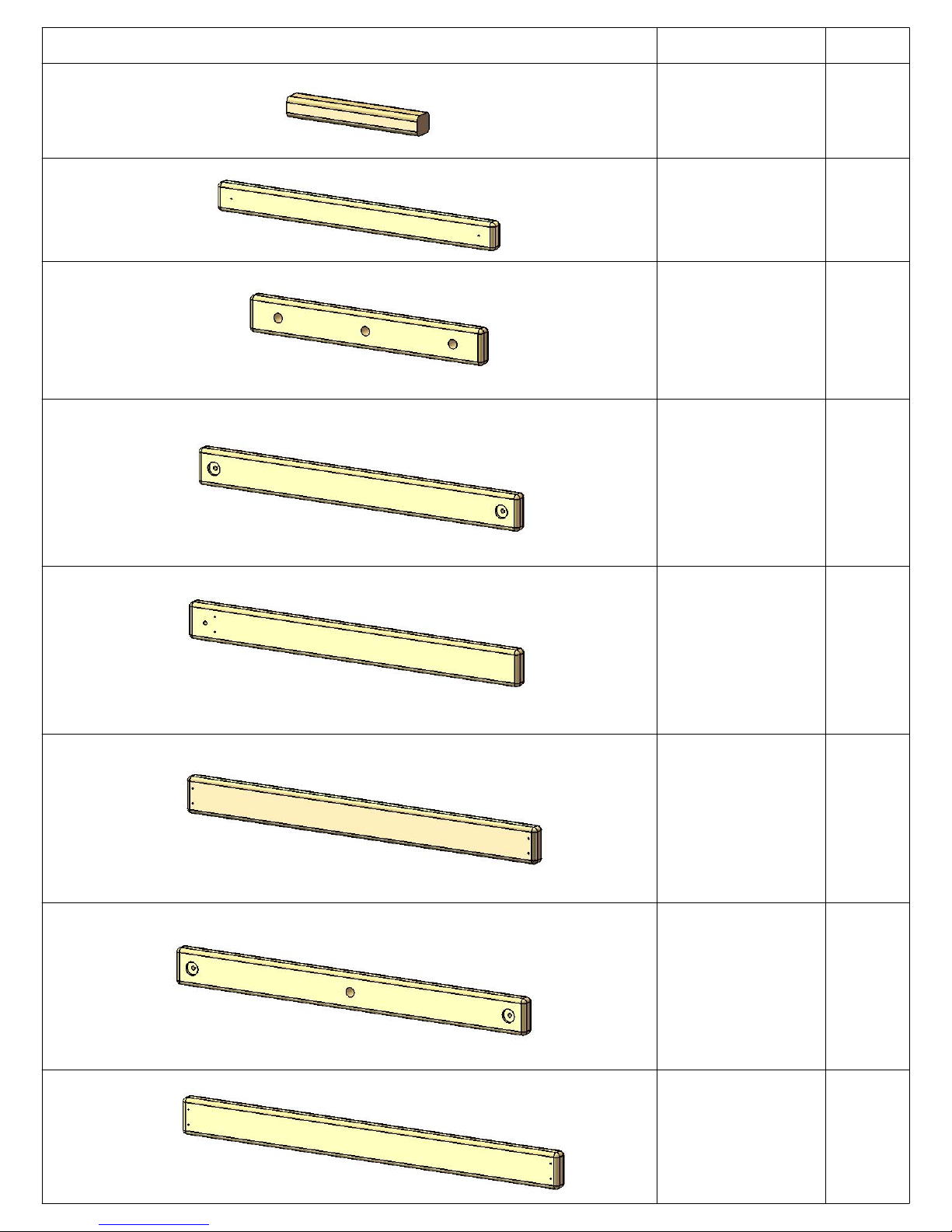
DESCRIPTIONPICTURE QTY.
18
TIC TAC TOE
BOARDS
1-3/8" X 1-5/8"
X 10-5/8"
2-2-1063-TTTB
2 X 3 X 28-1/2"
PANEL SLAT
2-3-2850-PS
2 X 4 X 24"
ROPE LADDER
RUNG
2-3-2400-RLST
2 X 4 X 33"
REAR BOTTOM
PANEL BOARD
2
4
6
1
2-4-3300-RBPB
2 X 4 X 34"
FRONT CENTER
POST
2-4-3400-FCP
2 X 4 X 36"
CENTER TARP
BOARD
2-4-3600-CTB
2 X 4 X 36"
ROCK WALL
ROPE SUPPORT
1
1
1
2-4-3600-RWRS
2 X 4 X 38-3/4"
TARP BOARD
2-4-3875-TB
2
Page 29

DESCRIPTIONPICTURE QTY.
19
2 X 4 X 47"
CENTER DECK
SUPPORT
2-4-4700-CDS
2 X 4 X 56"
ROCK WALL
BOTTOM
SUPPORT
2-4-5600-RWBS
2 X 4 X 58"
CROSS MEMBER
1
1
1
2-4-5800-CM
2 X 4 X 60" REAR
CENTER POST
2-4-6000-RCP
2 X 4 X 70-3/16"
ROPE LADDER
SUPPORT
2-4-7019-RLS
2 X 4 X 77"
SIDE RAIL
2-4-7700-SR
1
1
2
2 X 4 X 80"
ROPE LADDER
RUNNER
2-4-8000-RLR
1
Page 30
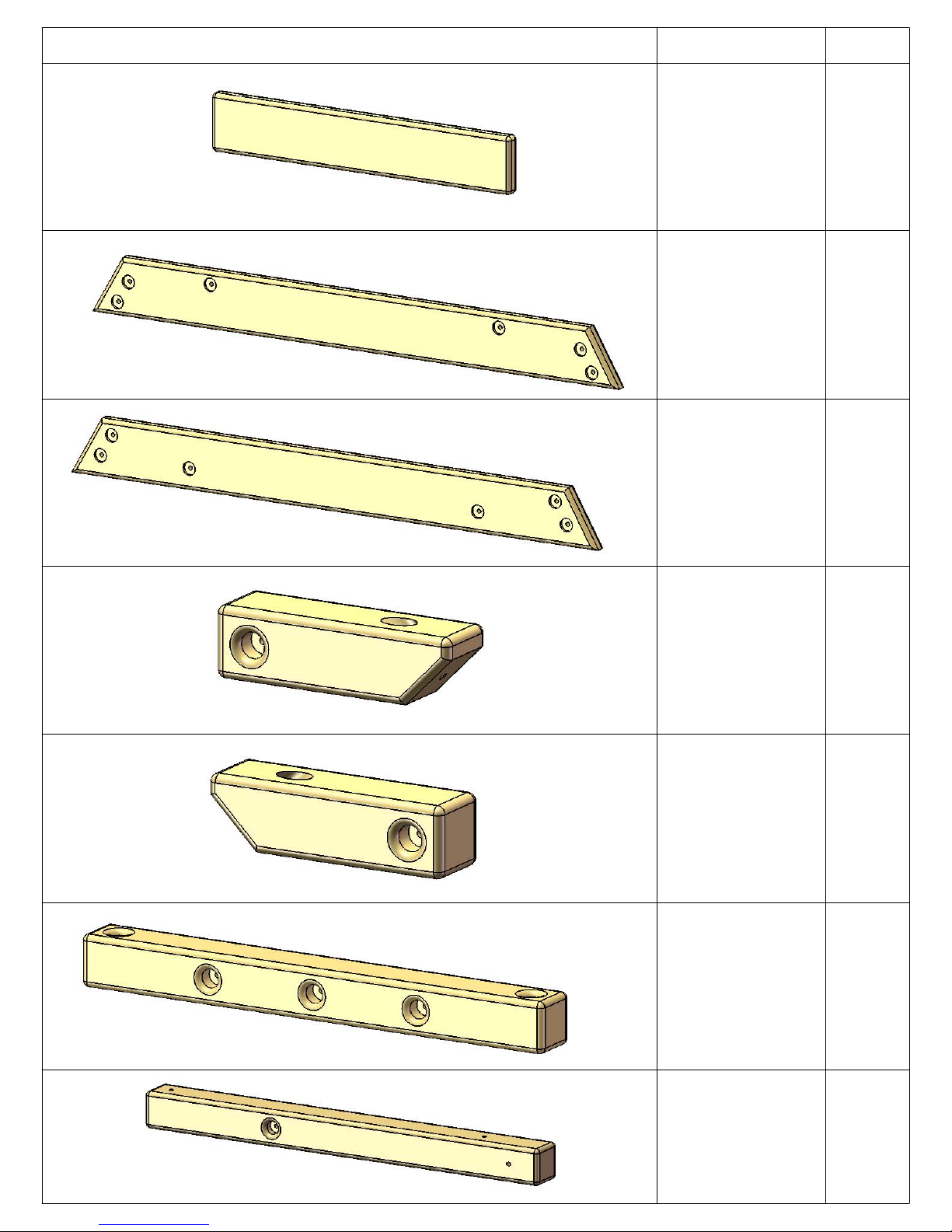
DESCRIPTIONPICTURE QTY.
20
2 X 6 X 30-3/4"
STEP
2-6-3075-SL
2 X 6 X 54-1/4"
INNER FORT
SUPPORT
2-6-5425-IFS
2 X 6 X 54-1/4"
OUTER FORT
SUPPORT
4
2
2
2-6-5425-OFS
4 X 4 X 12"
ANGLE
SUPPORT LEFT
SIDE
4-4-1200-ASLS
4 X 4 X 12"
ANGLE
SUPPORT
RIGHT SIDE
4-4-1200-ASRS
4 X 4 X 33-1/4"
SWING BEAM
SIDE RAIL
2
2
1
4-4-3325-SBSR
4 X 4 X 40-1/2"
CORNER POST
(LEFT)
4-4-4050-CPL
2
Page 31
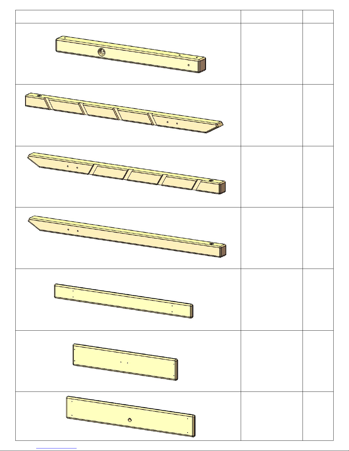
DESCRIPTIONPICTURE QTY.
21
4 X 4 X 40-1/2"
CORNER POST
(RIGHT)
4-4-4050-CPR
4 X 4 X 65-1/4"
LADDER LEFT
SIDE
4-4-6525-LLS
4 X 4 X 65-1/4"
LADDER RIGHT
SIDE
2
1
1
4-4-6525-LRS
4 X 4 X 65-1/4"
ROCK WALL
SIDE
4-4-6525-RWS
5/4 X 4 X 38-3/4"
CENTER DECK
BOARD
125-4-3875-CDB
5/4 X 6 X 29-1/4"
DECK SPACER
125-6-2925-DS
2
1
4
5/4 X 6 X 36"
BOTTOM ROCK
WALL BOARD
125-6-3600-BRWB
1
Page 32

DESCRIPTIONPICTURE QTY.
22
5/4 X 6 X 36"
ROCK WALL
BOARD
125-6-3600-RWB
5/4 X 6 X 38-3/4"
DECK BOARD
125-6-3875-DB
4 X 4 X 96"
SWING LEG
POLY COATED
8
4
2
99-0501
4 X 6 X 108"
SWING BEAM
POLY COATED
99-0601
8' WIKI
WAVE SLIDE
03-0015-G
36" X 117"
TARP
1
1
1
05-0008
SWING BELT
WITH CHAINS
04-0002
2
Page 33
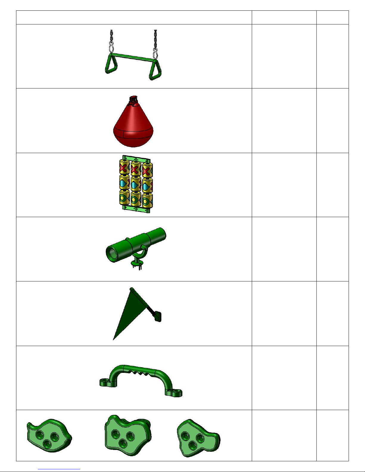
PICTURE DESCRIPTION QTY.
23
TRAPEZE SWING
WITH CHAINS
04-0006
PUNCHING BALL
1
04-0027
TIC TAC TOE
(UNASSEMBLED)
01-0010
TELESCOPE
07-0001
1
1
1
FLAG KIT
(PAIR)
09-1014
PLASTIC SAFETY
HANDLES (PAIR)
07-0005
ROCK WALL
ROCKS (PKG OF 5)
(COLOR & SIZE
MAY VARY)
07-0008
1
pr
2pr
10
rocks
Page 34

(CHAIN NOT SHOWN)
24
DESCRIPTIONPICTURE QTY.
CHAIN
1
08-1002
SPRING
CLIP
11-4003
IRON
DUCTILE
SWING
HANGER
ft
7
7
(3/4" DIAMETER ROPE NOT SHOWN)
11-4012
10 FT. ROPE -
ROCK WALL
13 FT. ROPE -
ROPE
LADDER
10-1004
SWING LEG
BRACKET
11-5010
SWING BEAM
PLATE
11-5002
PLASTIC
GROUND
STAKES
(PAIR)
1 PC.
3 PCS.
1
1
pr
1
(NOT SHOWN)
07-0016-P
LOGO
PLATE
1
Page 35
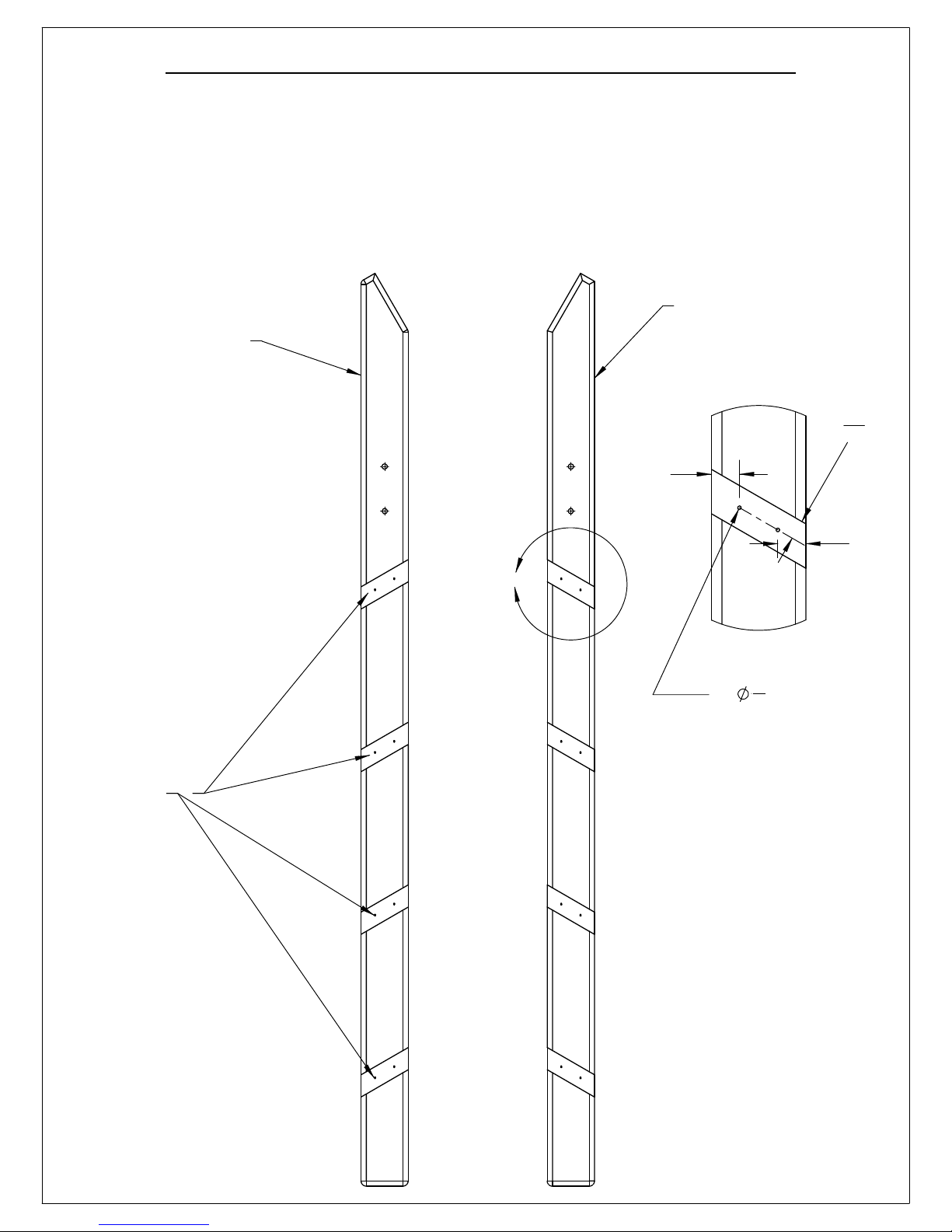
STEP 1: DRILLING HOLES FOR LADDER STEPS
25
1: LOCATE THE 4 X 4 X 65-1/4" LADDER SIDE-LEFT AND THE 4 X 4 X 65-1/4" LADDER SIDE RIGHT.
2: PLACE A SCRAP PIECE OF WOOD UNDERNEATH THE LADDER SIDE YOU ARE ABOUT TO
DRILL. DRILL TWO 1/8" DIAMETER HOLES ALONG THE CENTER OF EACH NOTCH THROUGH
THE LADDER SIDE PIECES. LOCATE EACH HOLE ABOUT 1" IN FROM THE SIDES AS SHOWN
BELOW. (SEE DETAIL A BELOW)
3: THESE HOLES WILL MAKE IT EASIER TO "HIT" THE LADDER STEPS WITH SCREWS DURING
ASSEMBLY IN THE NEXT STEP.
LADDER SIDE
LADDER SIDE
(LEFT)
(RIGHT)
DETAIL A
SCALE 1 : 4
11
16
1"
"
NOTCHED
AREAS
A
2X
1"
1
"
8
Page 36
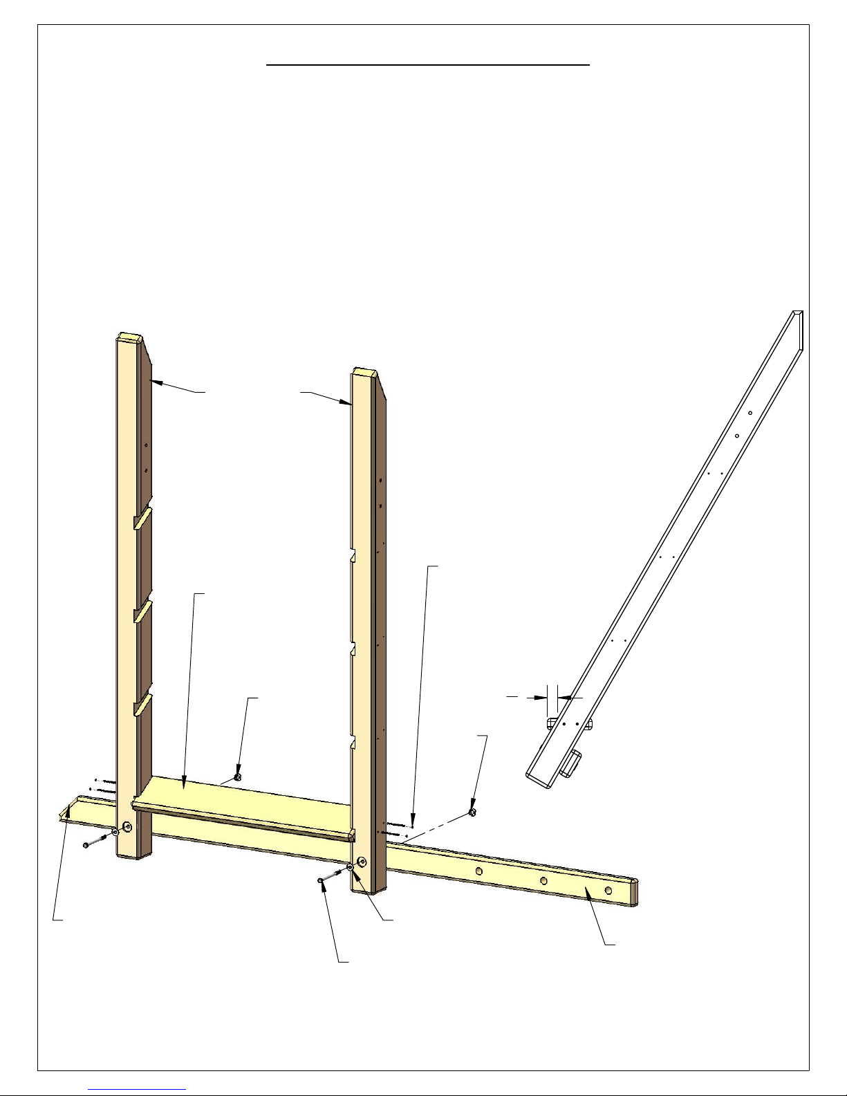
**STEP 1A: ADDENDUM**
26
1: BEFORE PROCEEDING TO STEP 2 INSTALL THE 2 X 4 X 80" ROPE LADDER RUNNER. LINE UP THE
HOLES IN THE ROPE LADDER RUNNER WITH THE HOLES IN THE LADDER SIDES.
2: INSTALL T-NUTS INTO THE HOLES IN THE BACK SIDE OF THE ROPE LADDER RUNNER.
3: FASTEN THE ROPE LADDER RUNNER TO THE LADDER SIDES WITH 5/16" X 4-1/2" HEX BOLTS
AND 5/16" WASHERS.
4: NOW PLACE A 2 X 6 X 30-3/4" LADDER STEP INSIDE THE NOTCHED AREA OF THE LADDER
SIDES AT THE BOTTOM NOTCH. LET THE FRONT EDGE OF THE STEP PROTRUDE PAST THE FRONT
SURFACE OF THE LADDER BY 1-1/4" AS SHOWN IN THE PICTURE AT THE RIGHT BELOW.
5: USE THE HOLES DRILLED IN STEP 1 TO FASTEN THE LADDER SIDES TO THE LADDER STEP WITH
#10 X 3-1/2" WOOD SCREWS.
LADDER SIDES
NOTE ANGLED END
2 X 6 X 30-3/4"
LADDER STEP
T-NUT
#10 X 3-1/2"
WOOD SCREW
(4 PER STEP)
T-NUT
5/16" WASHER
5/16" X 4-1/2" HEX BOLT
1
1
"
4
2 X 4 X 80"
ROPE LADDER RUNNER
Page 37

STEP 2: ASSEMBLING THE LADDER
27
1: INSTALL A T-NUT INTO THE HOLES ABOVE THE LADDER STEPS AS SHOWN BELOW. THE
TOPMOST HOLES GET A T-NUT ON THE INSIDE WHILE THE LOWER HOLES GET A T-NUT ON
THE OUTSIDE.
2: PLACE A 2 X 6 X 30-3/4" LADDER STEP INSIDE THE NOTCHED AREA OF EACH LADDER
SIDE. LET THE FRONT EDGE OF THE STEP PROTRUDE PAST THE FRONT SURFACE OF THE
LADDER BY 1-1/4" AS SHOWN IN THE PICTURE AT THE LOWER RIGHT BELOW.
3: USE THE HOLES DRILLED IN STEP 1 TO FASTEN THE LADDER SIDES TO THE LADDER STEPS
WITH #10 X 3-1/2" WOOD SCREWS.
T-NUT
4 X 4 X 65-1/4"
LADDER SIDE LADDER SIDE
(LEFT) (RIGHT)
T-NUT
T-NUT
2 X 6 X 30-3/4"
LADDER STEP
4 X 4 X 65-1/4"
T-NUT
#10 X 3-1/2"
WOOD SCREW
(4 PER STEP)
1
"
1
4
Page 38

STEP 3: ATTACHING ROPE LADDER RUNNER
28
1: LINE UP THE HOLES IN THE 2 X 4 X 80" ROPE LADDER RUNNER WITH THE HOLES IN THE
LADDER SIDES.
2: INSTALL T-NUTS INTO THE HOLES IN THE BACK SIDE OF THE ROPE LADDER RUNNER.
3: FASTEN THE ROPE LADDER RUNNER TO THE LADDER SIDES WITH 5/16" X 4-1/2" HEX BOLTS
AND 5/16" WASHERS.
NOTE: ONE STEP
HAS BEEN OMITTED
FOR CLARITY.
NOTE ANGLED END
T-NUT
T-NUT
5/16" WASHER
5/16" X 4-1/2" HEX BOLT
2 X 4 X 80"
ROPE LADDER
RUNNER
Page 39
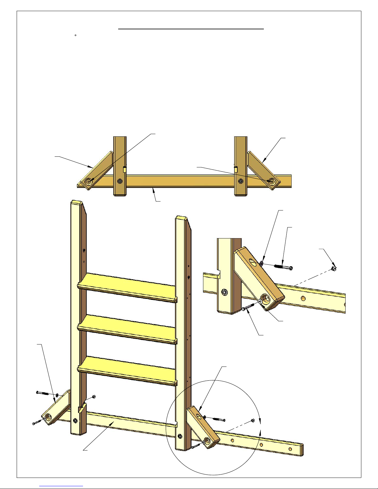
STEP 4: ANGLE SUPPORTS
29
1: PLACE THE 45 END OF A 4 X 4 X 12" ANGLE SUPPORT AGAINST THE SIDE OF EACH LADDER SIDE.
2: CENTER THE BOTTOM HOLE IN EACH ANGLE SUPPORT WITH THE MIDDLE OF THE ROPE LADDER RUNNER.
3: ATTACH EACH ANGLE SUPPORT THROUGH THE TOP HOLE TO THE LADDER SIDES WITH A 3/8" X 3-1/2" LAG
SCREW AND A 3/8" WASHER.
4: USE THE BOTTOM HOLE IN EACH ANGLE SUPPORT AS A GUIDE TO DRILL A 3/8" HOLE THROUGH THE ROPE
LADDER RUNNER. PLACE A SCRAP PIECE OF WOOD BEHIND THE ROPE LADDER RUNNER TO PREVENT THE
WOOD FROM SPLITTING OUT.
5: INSTALL T-NUTS IN THE BACK SIDE OF THE ROPE LADDER RUNNER.
6: ATTACH EACH ANGLE SUPPORT TO THE ROPE LADDER RUNNER WITH 5/16" X 3-1/2" HEX BOLTS AND 5/16"
WASHERS.
4 X 4 X 12"
ANGLE SUPPORT
(LEFT)
DRILL 3/8" HOLE THROUGH
ROPE LADDER RUNNER
AFTER ATTACHING EACH
ANGLE SUPPORT TO
LADDER SIDES AT TOP
HOLE WITH LAG SCREW
AND WASHER.
ROPE LADDER RUNNER
4 X 4 X 12"
ANGLE SUPPORT
(RIGHT)
3/8" WASHER
4 X 4 X 12"
ANGLE SUPPORT
(LEFT)
DETAIL A
SCALE 1 : 8
4 X 4 X 12"
ANGLE SUPPORT
(RIGHT)
3/8" X 3-1/2"
LAG SCREW
T-NUT
5/16" WASHER
5/16" X 3-1/2"
HEX BOLT
ROPE LADDER RUNNER
A
Page 40
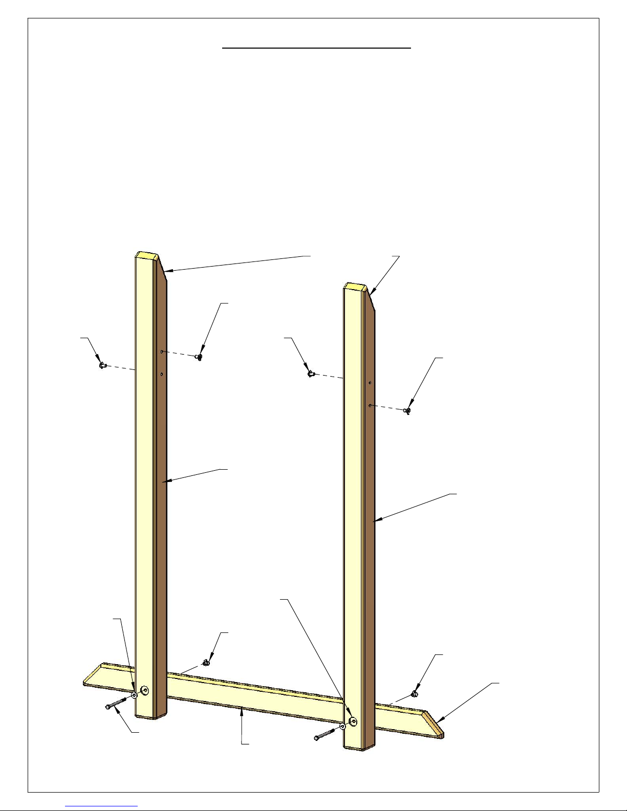
STEP 5: ROCK WALL
30
1: PLACE TWO 4 X 4 X 65-1/4" ROCK WALL SIDES AGAINST THE 2 X 4 X 56" ROCK WALL
BOTTOM SUPPORT. NOTE THE ANGLES ON THE ENDS OF THE ROCK WALL SIDES SHOULD
MATCH ONE ANOTHER AND THAT THE COUNTERBORED HOLES FACE OUT. ALSO NOTE
THE ANGLE ON THE ENDS OF THE ROCK WALL BOTTOM SUPPORT.
2: INSTALL T-NUTS INTO THE HOLES IN THE ROCK WALL SIDES. THE TOPMOST HOLES GET A
T-NUT ON THE INSIDE WHILE THE LOWER HOLES GET A T-NUT ON THE OUTSIDE.
3: INSTALL T-NUTS INTO THE HOLES ON THE BACK SIDE OF THE ROCK WALL BOTTOM
SUPPORT.
4: ATTACH THE ROCK WALL SIDES TO THE ROCK WALL BOTTOM SUPPORT WITH 5/16" X 41/2" HEX BOLTS AND 5/16" WASHERS.
ANGLES MATCH
T-NUT
T-NUT
5/16" WASHER
T-NUT
T-NUT
4 X 4 X 65-1/4"
ROCK WALL SIDE
4 X 4 X 65-1/4"
ROCK WALL SIDE
COUNTERBORED
HOLES
FACE OUT
T-NUT
5/16" X 4-1/2"
HEX BOLT
T-NUT
NOTE ANGLED
ENDS.
2 X 4 X 56"
ROCK WALL
BOTTOM SUPPORT
Page 41
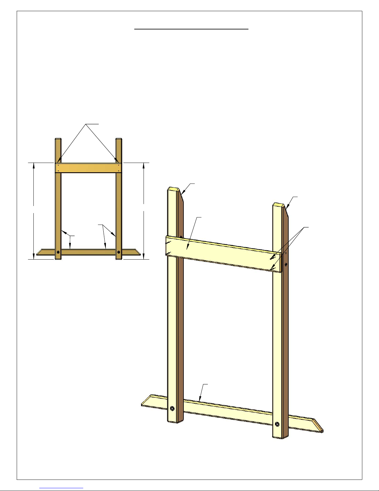
STEP 6: ROCK WALL
31
1: MEASURE 52" FROM THE BOTTOM OF EACH OF THE ROCK WALL SIDES AND MAKE A
MARK ONTO THE ROCK WALL SIDES.
2: BEFORE INSTALLING THE ROCK WALL BOARD MAKE SURE THAT THE ROCK WALL SIDES
ARE SQUARE TO THE ROCK WALL BOTTOM SUPPORT.
3: ALIGN THE TOP SURFACE OF A 5/4 X 6 X 36" ROCK WALL BOARD WITH THE MARKS.
4: FASTEN THE ROCK WALL BOARD TO THE ROCK WALL SIDES WITH #8 X 2" WOOD
SCREWS.
MAKE A MARK HERE
ONTO ROCK WALL SIDES.
ROCK WALL SIDE
ROCK WALL SIDE
52"
SQUARE
SQUARE
52"
5/4 X 6 X 36"
ROCK WALL BOARD
ROCK WALL
BOTTOM SUPPORT
#8 X 2"
WOOD
SCREW
Page 42
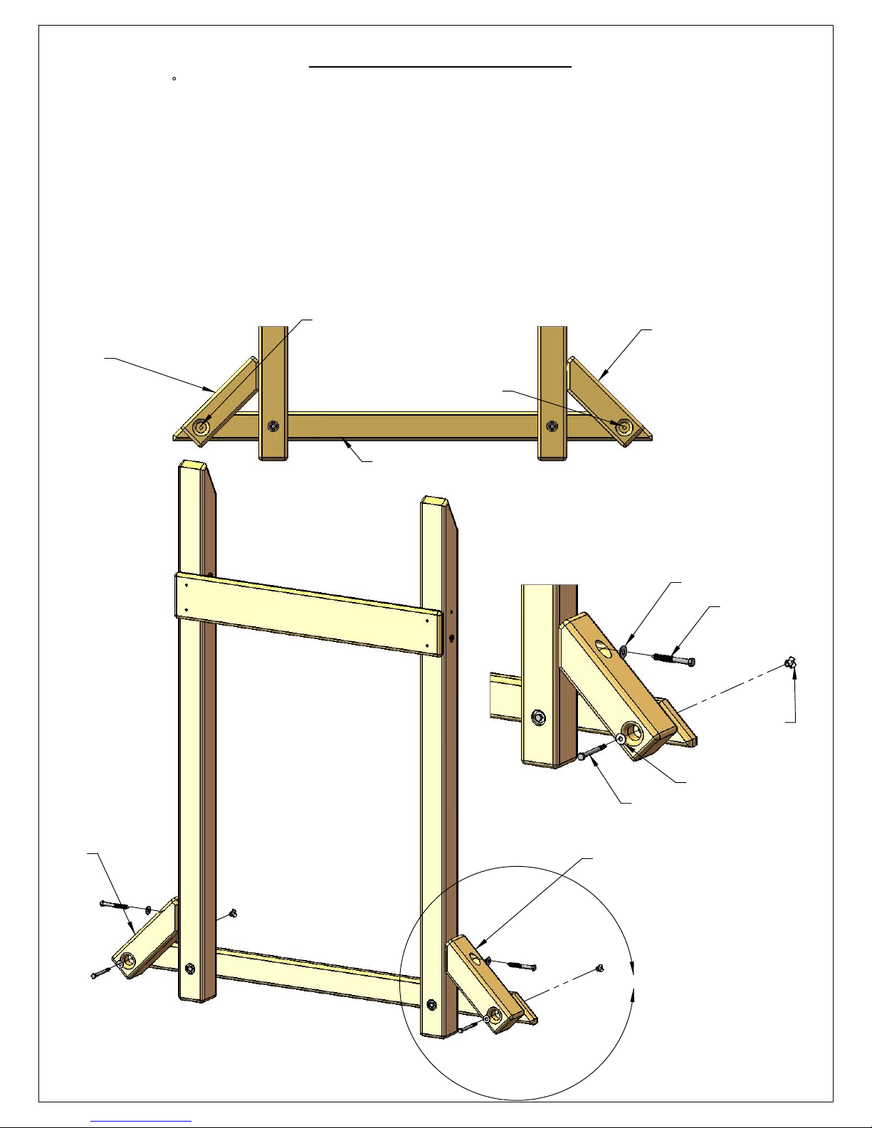
STEP 7: ROCK WALL
32
1: PLACE THE 45 END OF A 4 X 4 X 12" ANGLE SUPPORT AGAINST THE SIDE OF EACH ROCK WALL SIDE.
2: CENTER THE BOTTOM HOLE IN EACH ANGLE SUPPORT WITH THE MIDDLE OF THE ROCK WALL BOTTOM
SUPPORT.
3: ATTACH EACH ANGLE SUPPORT THROUGH THE TOP HOLE TO THE LADDER SIDES WITH A 3/8" X 3-1/2" LAG
SCREW AND A 3/8" WASHER.
4: USE THE BOTTOM HOLE IN EACH ANGLE SUPPORT AS A GUIDE TO DRILL A 3/8" HOLE THROUGH THE ROCK
WALL BOTTOM SUPPORT. PLACE A SCRAP PIECE OF WOOD BEHIND THE ROCK WALL BOTTOM SUPPORT TO
PREVENT THE WOOD FROM SPLITTING OUT.
5: INSTALL T-NUTS IN THE BACK SIDE OF THE ROCK WALL BOTTOM SUPPORT.
6: ATTACH EACH ANGLE SUPPORT TO THE ROCK WALL BOTTOM SUPPORT WITH 5/16" X 3-1/2" HEX BOLTS
AND 5/16" WASHERS.
4 X 4 X 12"
ANGLE SUPPORT
(LEFT)
DRILL 3/8" HOLE THROUGH
ROCK WALL BOTTOM SUPPORT
AFTER ATTTACHING EACH
ANGLE SUPPORT TO ROCK
WALL SIDES AT TOP HOLE WITH
LAG SCREW AND WASHER.
ROCK WALL
BOTTOM SUPPORT
4 X 4 X 12"
ANGLE SUPPORT
(RIGHT)
4 X 4 X 12"
ANGLE SUPPORT
(LEFT)
DETAIL A
SCALE 1 : 8
3/8" WASHER
3/8" X 3-1/2"
LAG SCREW
T-NUT
5/16" WASHER
5/16" X 3-1/2"
HEX BOLT
4 X 4 X 12"
ANGLE SUPPORT
(RIGHT)
A
Page 43
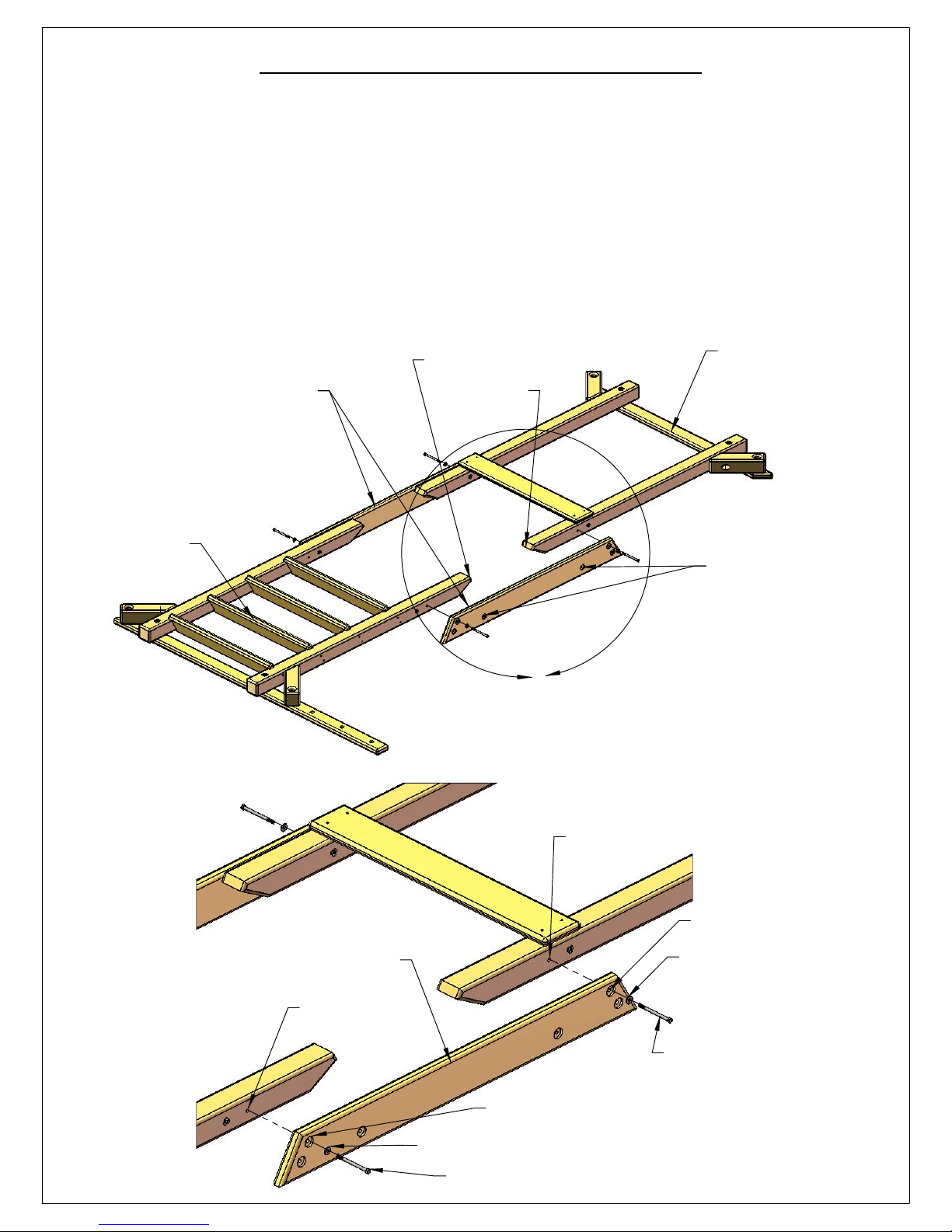
STEP 8: OUTER FORT SUPPORTS
33
1: LAY THE ROCK WALL ASSEMBLY AND THE LADDER ASSEMBLY DOWN ON A FLAT
SURFACE WITH THE ANGLED ENDS FACING EACH OTHER.
2: PLACE A 2 X 6 X 54-1/4" OUTER FORT SUPPORT ON THE OUTSIDE OF THE ROCK
WALL/LADDER SIDES. NOTE THE OUTER FORT SUPPORT HAS TWO HOLES IN THE MIDDLE OF
THE BOARD CLOSEST TO THE BOTTOM. THE COUNTERBORED HOLES IN THE OUTER FORT
SUPPORT FACE OUT.
3: LINE UP THE TOP HOLE IN EACH END OF THE OUTER FORT SUPPORT WITH THE TOP HOLE
IN THE ROCK WALL/LADDER SIDES.
4: ATTACH THE OUTER FORT SUPPORT TO THE ROCK WALL/LADDER SIDES WITH 5/16" X 41/2" HEX BOLTS AND 5/16" WASHERS.
2 X 6 X 54-1/4"
OUTER FORT SUPPORT
LADDER
ASSEMBLY
ANGLED
ENDS FACE
EACH OTHER.
ROCK WALL
ASSEMBLY
IN OUTER FORT SUPPORT
THE MIDDLE COUNTER
BORED HOLES ARE
CLOSEST TO THE BOTTOM
OF THE BOARD.
ALL COUNTERBORES
FACE OUT.
A
DETAIL A
SCALE 1 : 12
2 X 6 X 54-1/4"
OUTER FORT SUPPORT
TOP HOLE IN
LADDER.
TOP HOLE
IN ROCK
WALL SIDE.
TOP HOLE IN OUTER
FORT SUPPORT
5/16" WASHER
5/16" X 4-1/2"
HEX BOLT
TOP HOLE IN
OUTER FORT SUPPORT.
5/16" WASHER
5/16" X 4-1/2" HEX BOLT
Page 44
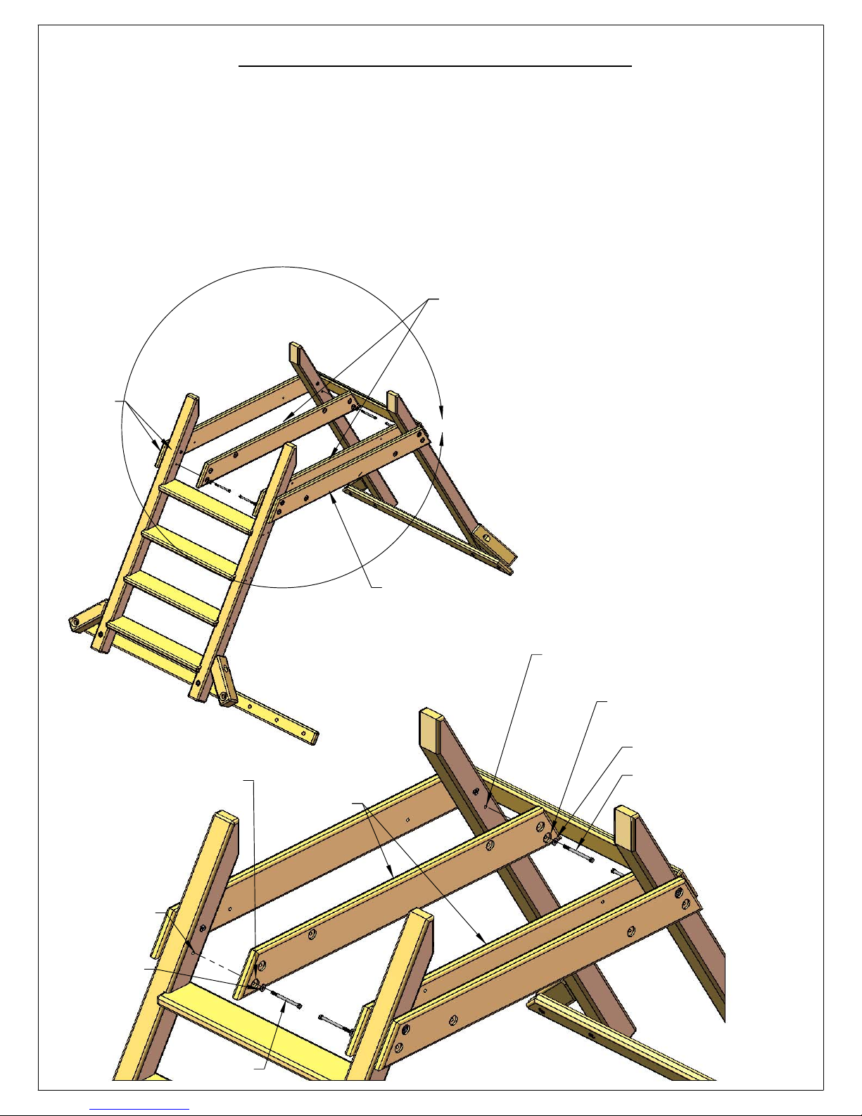
STEP 9: INNER FORT SUPPORTS
34
1: HAVE AN ASSISTANT HELP YOU LIFT THE OUTER FORT SUPPORTS UP AS THE ROCK WALL
ASSEMBLY AND LADDER ENDS TILT UP. THE OUTER SURFACE OF THE LADDER AND ROCK
WALL SIDES SHOULD BE FLUSH TO THE ENDS OF THE OUTER FORT SUPPORTS. HAVE YOUR
ASSISTANT HOLD THE ASSEMBLY UP WHILE YOU INSTALL THE INNER FORT SUPPORTS.
2: PLACE A 2 X 6 X 54-1/4" INNER FORT SUPPORT ON THE INSIDE OF THE ROCK
WALL/LADDER SIDES AS SHOWN. LINE UP THE BOTTOM HOLE IN EACH END OF THE INNER
FORT SUPPORT WITH THE BOTTOM HOLE IN THE ROCK WALL/LADDER SIDE.
3: ATTACH THE INNER FORT SUPPORT TO THE ROCK WALL/LADDER SIDE WITH 5/16" X 4-1/2'
HEX BOLTS AND 5/16" WASHERS.
2 X 6 X 54-1/4"
INNER FORT
SUPPORT
FLUSH
A
BOTTOM HOLE IN
INNER FORT SUPPORT
BOTTOM
HOLE IN
LADDER
ASSEMBLY
5/16" WASHER
2 X 6 X 54-1/4"
INNER FORT
SUPPORT
OUTER FORT SUPPORT
(LIFT UP ON EACH SIDE)
BOTTOM HOLE IN
ROCK WALL.
BOTTOM HOLE IN
INNER FORT SUPPORT
5/16" WASHER
5/16" X 4-1/2"
HEX BOLT
5/16" X 4-1/2"
HEX BOLT
DETAIL A
SCALE 1 : 12
Page 45
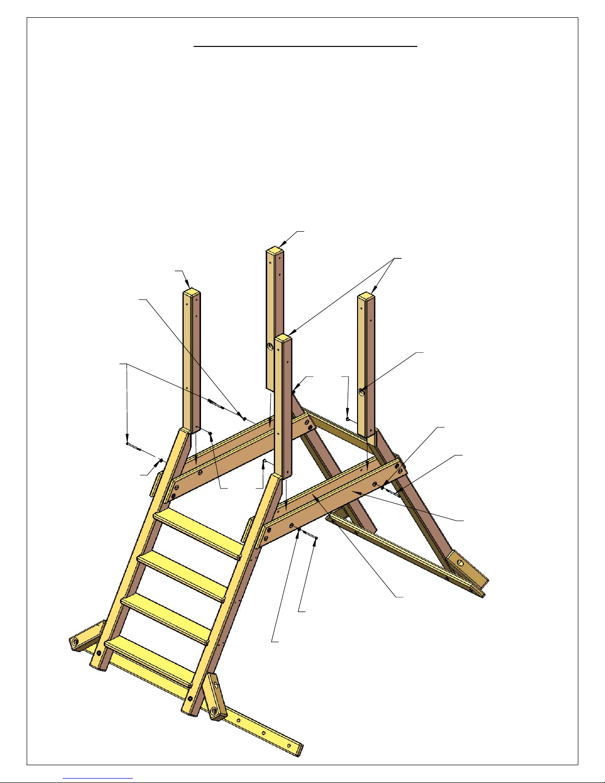
STEP 10: CORNER POSTS
35
1: LOCATE TWO 4 X 4 X 40-1/2" CORNER POST - LEFT AND TWO 4 X 4 X 40-1/2" CORNER
POST - RIGHT. THE CORNER POST - RIGHT HAS THREE HOLES IN THE TOP AND THE CORNER
POST - LEFT HAS TWO HOLES IN THE TOP. THE COUNTERBORED HOLES IN THE CORNER
POSTS FACE EACH OTHER ON THE INSIDE OF THE ASSEMBLY.
2: INSTALL A T-NUT INTO THE BOTTOM HOLE OF EACH CORNER POST ON THE INSIDE AS
SHOWN.
3: PLACE THE BOTTOM END OF EACH CORNER POST BETWEEN THE INNER AND OUTER
FORT SUPPORTS AND LINE UP THE BOTTOM HOLE IN THE CORNER POST WITH THE HOLE IN
THE OUTER FORT SUPPORT.
4: ATTACH EACH CORNER POST TO THE OUTER FORT SUPPORTS WITH 5/16" X 4-1/2" HEX
BOLTS AND 5/16" WASHERS.
CORNER POST - RIGHT
CORNER POST - LEFT
CORNER POST - RIGHT
5/16" WASHER
5/16" X 4-1/2"
HEX BOLT
5/16" WASHER
COUNTERBORED HOLES
FACE EACH OTHER ON
T-NUT
T-NUT
5/16" X 4-1/2"
HEX BOLT
THE INSIDE.
5/16" WASHER
5/16" X 4-1/2"
HEX BOLT
OUTER FORT
SUPPORT
INNER
FORT
SUPPORT
5/16" WASHER
Page 46
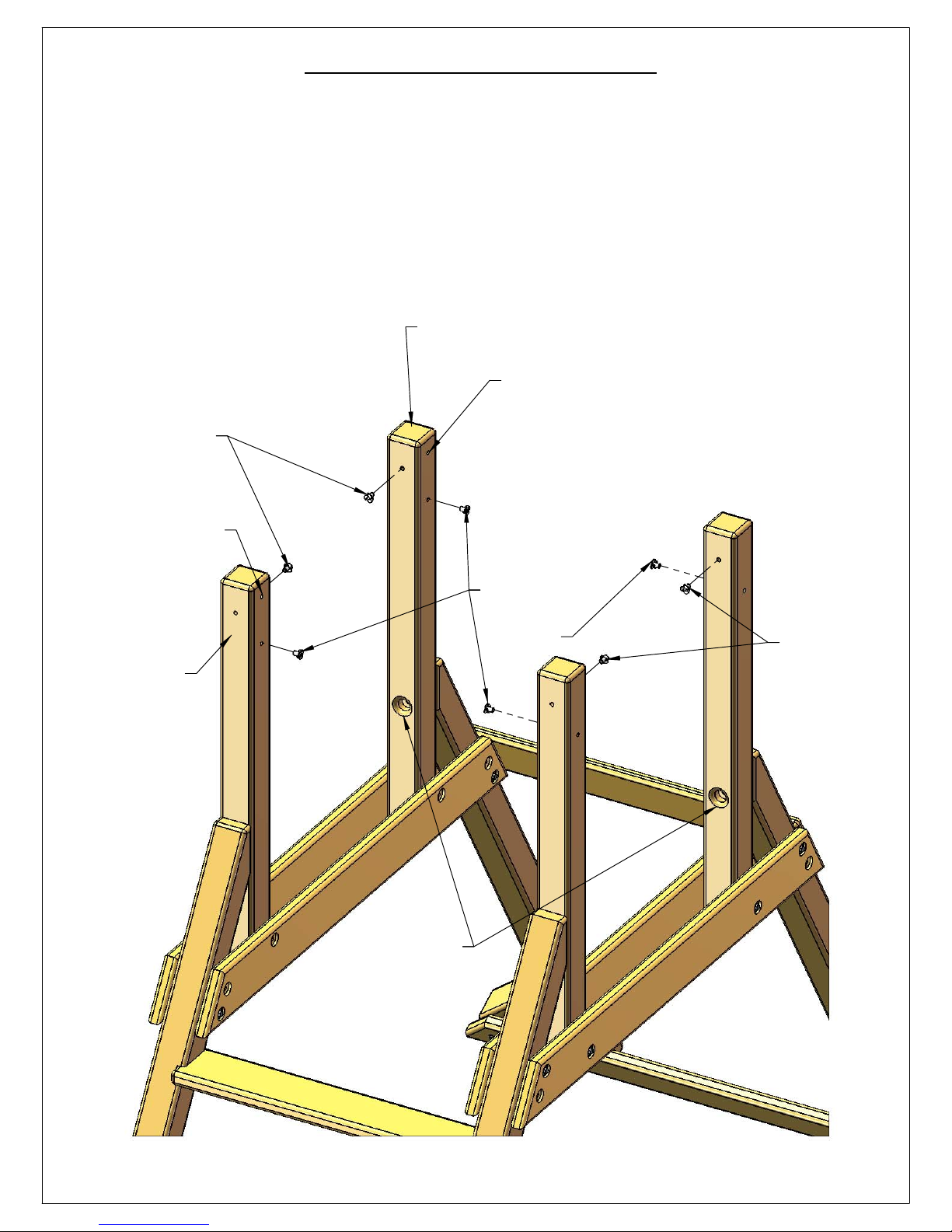
STEP 11: CORNER POSTS
36
1: INSTALL T-NUTS IN THE BOTTOM HOLES ON THE INSIDE OF THE CORNER POSTS.
2: INSTALL T-NUTS IN THE TOP HOLES ON THE INSIDE OF THE CORNER POSTS ABOVE THE
COUNTERBORED HOLES.
3: DO NOT INSTALL T-NUTS IN THE TOP HOLES ON THE INSIDE TOP MOST HOLES OF THE
CORNER POST - RIGHT BOARDS.
CORNER POST - RIGHT
T-NUTS IN
TOP HOLES ON
INSIDE ABOVE
COUNTERBORED
HOLES.
NO T-NUT IN THIS HOLE
CORNER POST
- RIGHT
NO T-NUT IN THIS HOLE
T-NUTS IN
BOTTOM
HOLES ON
INSIDE.
T-NUTS IN
TOP HOLES ON
INSIDE ABOVE
COUNTERBORED
HOLES.
COUNTERBORED
HOLES
Page 47
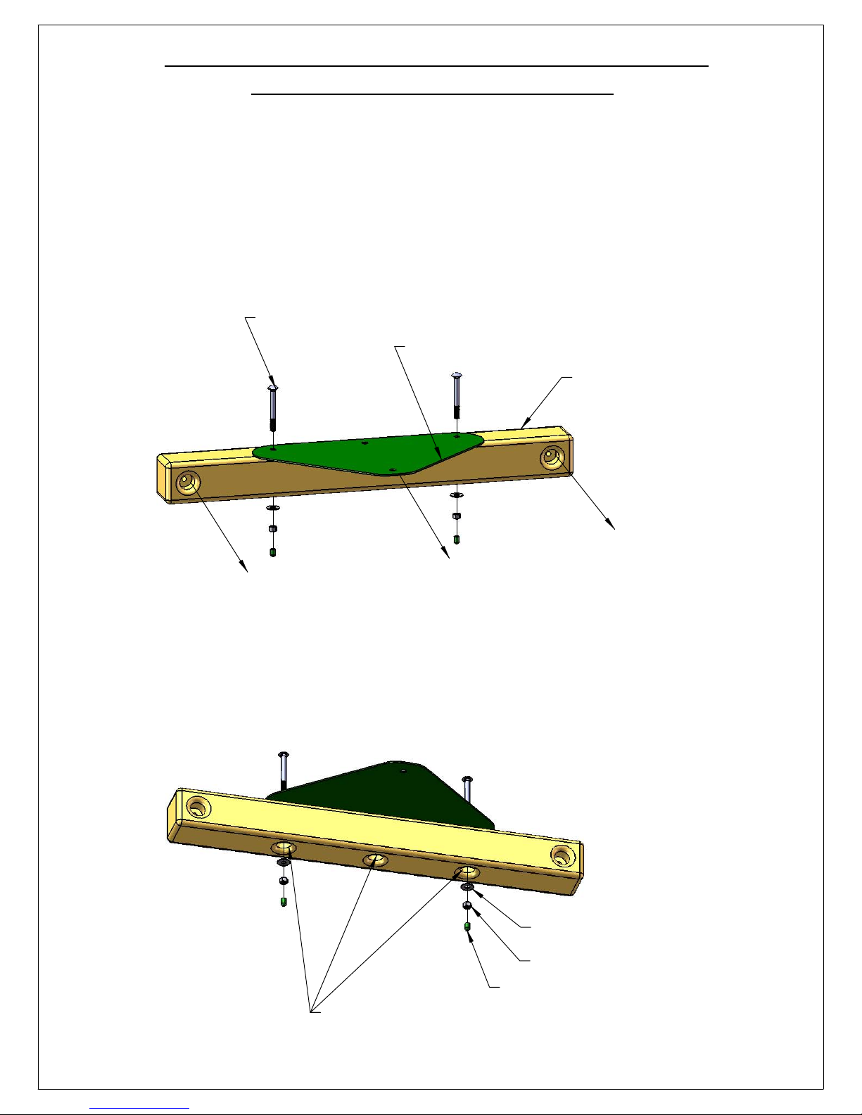
STEP 12: ATTACH SWING BEAM PLATE TO
37
THE SWING BEAM SIDE RAIL
1: LOCATE THE 4 X 4 X 33-1/4" SWING BEAM SIDE RAIL AND THE SWING BEAM PLATE.
2: PLACE THE SWING BEAM PLATE OVER THE THREE SMALL HOLES IN THE SWING BEAM
SIDE RAIL. THE TWO COUNTERBORED HOLES IN THE ENDS OF THE BEAM SHOULD FACE THE
SAME DIRECTION AS THE POINTED END OF THE SWING BEAM PLATE. THE THREE
COUNTERBORED HOLES IN THE MIDDLE OF THE BEAM SHOULD FACE DOWN.
3: FASTEN THE SWING BEAM PLATE TO THE SWING BEAM SIDE RAIL WITH 3/8" X 3-1/2"
CARRIAGE BOLTS IN TOP AND 3/8" WASHERS, 3/8" LOCK NUTS ON THE BOTTOM. PLACE
BOLT CAPS OVER ANY EXPOSED THREADS.
3/8" X 3-1/2" CARRIAGE BOLT
SWING BEAM PLATE
4 X 4 X 33-1/4"
SWING BEAM SIDE RAIL
POINTED END OF SWING BEAM PLATE
FACES SAME DIRECTION AS TWO COUNTERBORES
IN ENDS OF SWING BEAM SIDE RAIIL.
3/8" WASHER
3/8" LOCK NUT
BOLT CAP
THREE COUNTERBORED HOLES FACE DOWN.
Page 48
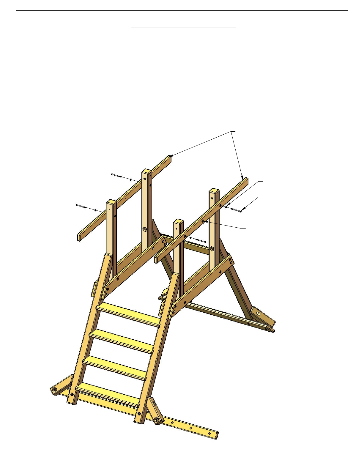
STEP 13: SIDE RAILS
38
1: LOCATE TWO 2 X 4 X 77" SIDE RAILS.
2: PLACE EACH SIDE RAIL AGAINST THE CORNER POSTS ON THE OUTSIDE WITH THE
COUNTERBORED HOLES FACING OUT.
3: ALIGN THE HOLES IN EACH SIDE RAIL TO THE HOLES IN THE CORNER POSTS.
4: LOOSELY ATTACH EACH SIDE RAIL TO THE CORNER POSTS WITH 5/16" X 4-1/2" HEX
BOLTS AND 5/16" WASHERS.
2 X 4 X 77" SIDE RAIL
5/16" WASHER
5/16" X 4-1/2"
HEX BOLT
COUNTERBORED HOLES
FACE OUT.
Page 49
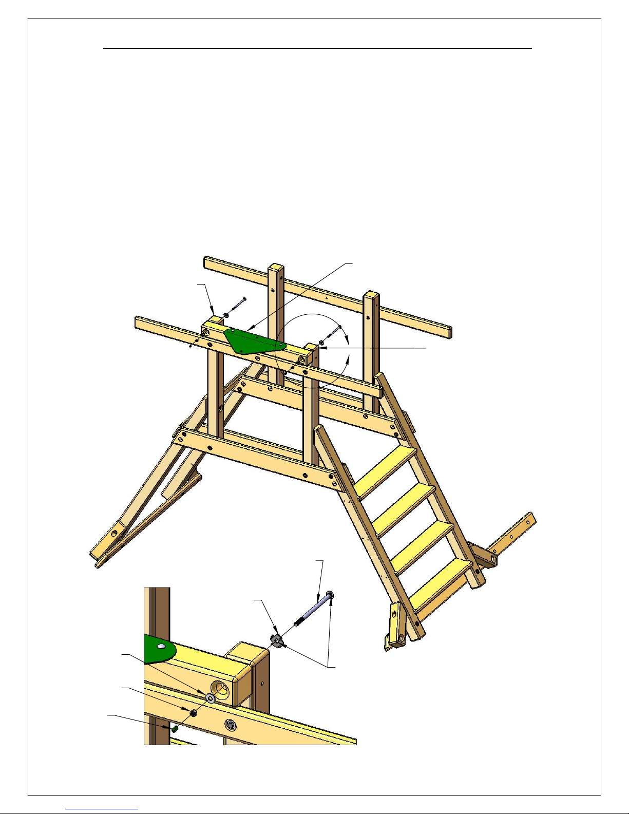
STEP 14: ATTACHING SWING BEAM SIDE RAIL
39
1: PLACE THE 4 X 4 X 33-1/4" SWING BEAM SIDE RAIL/SWING BEAM PLATE ASSEMBLY
AGAINST THE RIGHT CORNER POSTS. THE SWING BEAM PLATE SHOULD FACE UP.
2: LINE UP THE HOLES IN THE SWING BEAM SIDE RAIL WITH THE HOLES IN THE RIGHT
CORNER POSTS.
3: PLACE A 3/8" X 6-1/2" CARRIAGE BOLT AND TORQUE WASHER INTO THE HOLES AT THE
TOP OF THE RIGHT CORNER POSTS ON THE INSIDE. LINE UP THE SQUARE SHANK OF THE
CARRIAGE BOLT WITH THE SQUARE HOLE IN THE TORQUE WASHER. USE A HAMMER TO HIT
THE TOP OF THE CARRIAGE BOLT TO SET THE TORQUE WASHER TEETH INTO THE WOOD.
HOLD THE CORNER POST STEADY WHILE YOU HAMMER THE CARRIAGE BOLT.
4: FASTEN THE SWING BEAM SIDE RAIL TO THE RIGHT CORNER POSTS WITH 3/8" WASHERS
AND 3/8" LOCK NUTS ON THE INSIDE OF THE COUNTERBORED HOLES. PLACE BOLT CAPS
OVER ANY EXPOSED THREADS ON THE ENDS OF THE CARRIAGE BOLTS.
SWING BEAM SIDE RAIL/SWING BEAM PLATE
RIGHT CORNER POST
TOP HOLE IS EMPTY
ASSEMBLY
3/8" X 6-1/2"
CARRIAGE BOLT
TORQUE WASHER
(TEETH GET HAMMERED
INTO WOOD)
A
RIGHT CORNER POST
TOP HOLE IS EMPTY
3/8" WASHER
3/8" LOCK NUT
BOLT CAP
LINE UP SQUARE
HOLE WITH SQUARE
SHANK OF CARRIAGE
BOLT.
DETAIL A
SCALE 1 : 7
Page 50
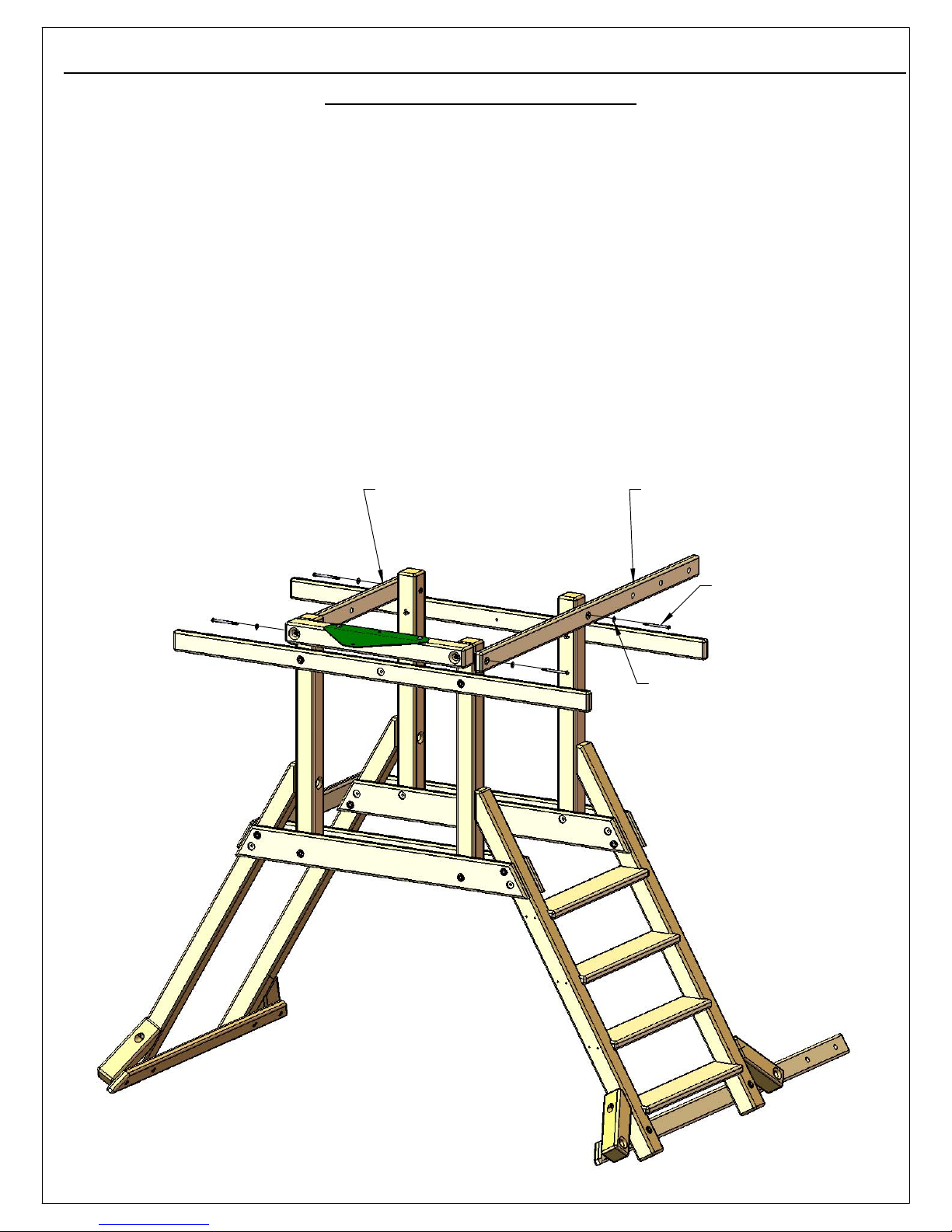
STEP 15: ATTACHING ROPE LADDER SUPPORT AND ROCK
40
WALL ROPE SUPPORT
1: FIND THE 2 X 4 X 70-3/16" ROPE LADDER SUPPORT AND LAY IT ON TOP OF THE SIDE
RAILS. THE COUNTERBORED HOLES IN THE ROPE LADDER SUPPORT FACE OUT.
2: LINE UP THE HOLES IN THE ROPE LADDER SUPPORT WITH THE HOLES IN THE CORNER
POSTS.
3: ATTACH THE ROPE LADDER SUPPORT TO THE CORNER POSTS WITH 5/16" X 4-1/2" HEX
BOLTS AND 5/16" WASHERS.
4: FIND THE 2 X4 X 36" ROCK WALL ROPE SUPPORT AND LAY IT ON TOP OF THE SIDE RAILS.
5: LINE UP THE HOLES IN THE ROCK WALL ROPE SUPPORT WITH THE HOLES IN THE CORNER
POSTS.
6: ATTACH THE ROCK WALL ROPE SUPPORT TO THE CORNER POSTS WITH 5/16" X 4-1/2"
HEX BOLTS AND 5/16" WASHERS. THE COUNTERBORED HOLES IN THE ROCK WALL ROPE
SUPPORT FACE OUT.
2 X 4 X 36"
ROCK WALL ROPE SUPPORT
2 X 4 X 70-3/16"
ROPE LADDER SUPPORT
5/16" X 4-1/2"
HEX BOLT
5/16" WASHER
Page 51
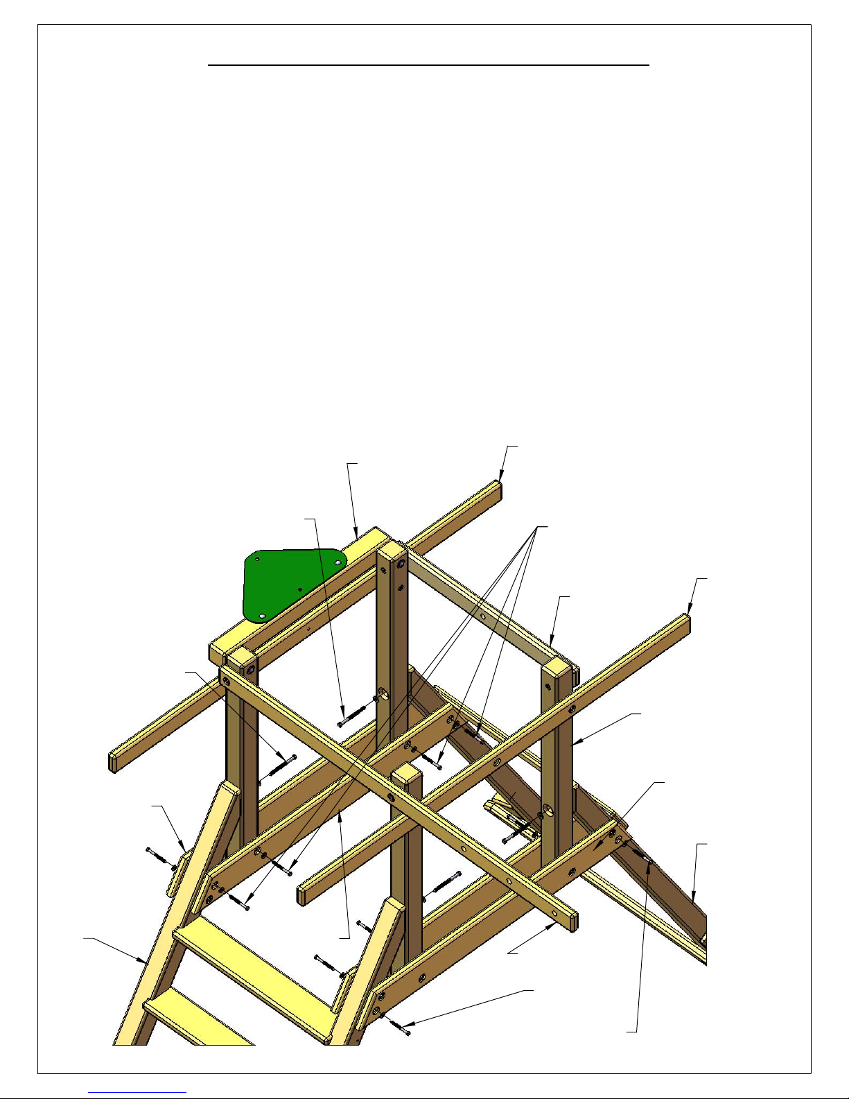
STEP 16: INSTALLING LAG SCREWS
41
1: MAKE SURE THE UNIT IS LEVEL AND SQUARE.
2: MAKE SURE THE LADDER LEG SIDES AND CORNER POST SIDES ARE FLUSH. INSTALL 3/8" X
5" LAG SCREWS WITH 3/8" WASHERS INTO THE COUNTERBORED HOLES IN THE CORNER
POSTS TO CONNECT THE CORNER POSTS TO THE LADDER SIDES.
3: MAKE SURE THE ROCK WALL SIDES AND THE CORNER POST SIDES ARE FLUSH. INSTALL
3/8" X 5" LAG SCREWS WITH 3/8" WASHERS INTO THE COUNTERBORED HOLES IN THE
CORNER POSTS TO CONNECT THE CORNER POSTS TO THE ROCK WALL SIDES.
4: FASTEN THE OUTER FORT SUPPORTS TO THE LADDER AND ROCK WALL SIDES WITH 3/8" X
3-1/2" LAG SCREWS AND 3/8" WASHERS.
5: NOW GO BACK AND TIGHTEN ALL THE BOLTS THAT FASTEN THE SIDE RAILS, ROPE
LADDER SUPPORT, ROCK WALL ROPE SUPPORT AND SWING BEAM SIDE RAIL TO THE
CORNER POSTS.
6: FINALLY INSTALL 3/8" X 3-1/2" LAG SCREWS WITH 3/8" WASHERS INTO THE FOUR HOLES
IN EACH INNER FORT SUPPORT. THIS WILL CONNECT THE INNER FORT SUPPORTS TO THE
LADDER SIDE, CORNER POSTS AND ROCK WALL SIDE.
SIDE RAIL
SWING BEAM
3/8" X 5"
LAG SCREW
WITH
3/8" WASHER
3/8" X 5"
LAG SCREW
WITH
3/8" WASHER
SIDE RAIL
3/8" X 3-1/2"
LAG SCREW
WITH
3/8" WASHER
ROCK WALL
ROPE SUPPORT
SIDE RAIL
OUTER FORT
SUPPORT
LADDER
SIDE
INNER FORT
SUPPORT
CORNER POST
OUTER FORT
SUPPORT
ROCK WALL
SIDE
ROPE LADDER
SUPPORT
3/8" X 3-1/2"
LAG SCREW
WITH
3/8" WASHER
Page 52
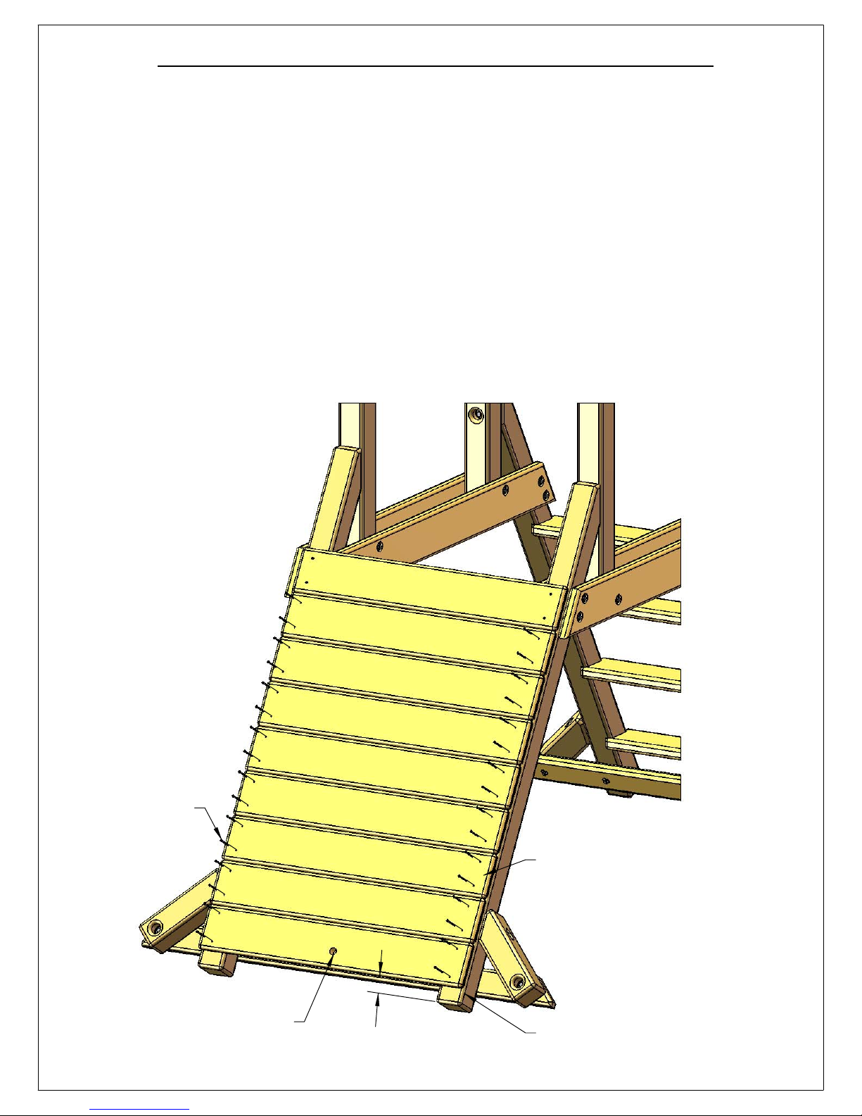
STEP 17: INSTALLING ROCK WALL BOARDS
42
1: INSTALL THE LOWER SURFACE OF THE BOTTOM ROCK WALL BOARD 2" FROM THE
BOTTOM OF THE ROCK WALL SIDES. FASTEN THE BOTTOM ROCK WALL BOARD TO THE
ROCK WALL SIDES WITH FOUR #8 X 2" WOOD SCREWS.
2: PLACE SEVEN ROCK WALL BOARDS BETWEEN THE BOTTOM ROCK WALL BOARD AND
THE TOP ROCK WALL BOARD THAT IS ALREADY INSTALLED. EQUALLY SPACE THE ROCK
WALL BOARDS. THERE WILL BE A 1/16" TO 3/16" GAP BETWEEN BOARDS DEPENDING
UPON MILLING VARIATIONS.
3: ATTACH EACH ROCK WALL BOARD TO THE ROCK WALL SIDES WITH FOUR #8 X 2"
WOOD SCREWS.
#8 X 2"
WOOD
SCREWS
BOTTOM ROCK WALL BOARD
(HOLE IS OFFSET DOWN)
2"
ROCK WALL BOARD
ROCK WALL SIDE
Page 53
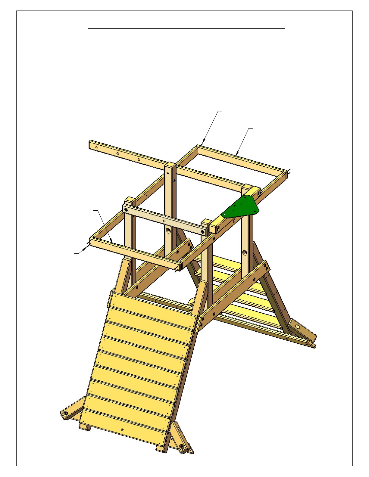
STEP 18: INSTALLING TARP BOARDS
43
1: LOCATE TWO 2 X 4 X 38-3/4" TARP BOARDS.
2: PLACE A TARP BOARD AT THE END OF THE SIDE RAILS. THE TARP BOARD TOP SHOULD
BE FLUSH TO THE TOP OF THE SIDE RAILS. THE TARP BOARD ENDS SHOULD BE FLUSH TO THE
OUTSIDE OF THE SIDE RAILS.
3: FASTEN EACH TARP BOARD TO THE SIDE RAILS WITH FOUR #8 X 2-1/2" WOOD SCREWS.
#8 X 2-1/2"
WOOD SCREW
2 X 4 X 38-3/4"
TARP BOARD
2 X 4 X 38-3/4"
TARP BOARD
#8 X 2-1/2"
WOOD SCREW
Page 54
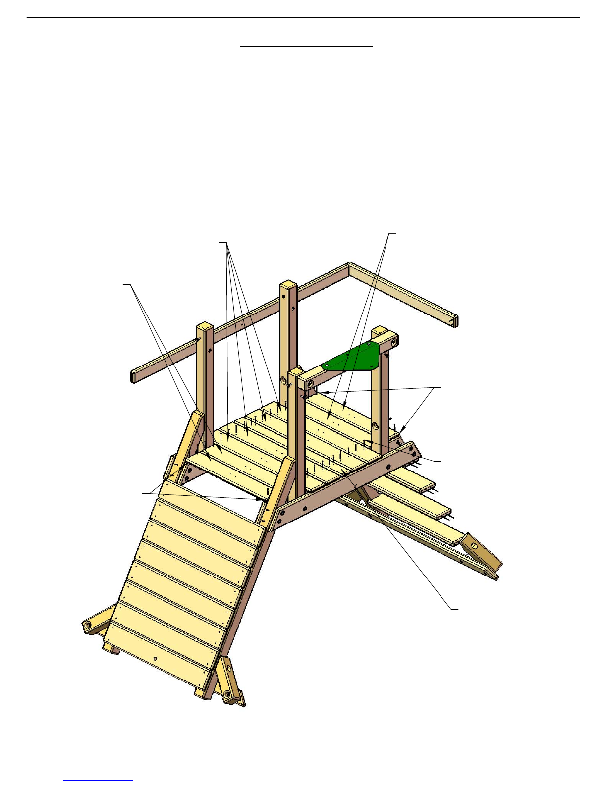
STEP 19: DECK
44
1: LOCATE FOUR 5/4 X 6 X 38-3/4" DECK BOARDS, FOUR 5/4 X 6 X 29-1/4" DECK SPACERS
AND ONE 5/4 X 4 X 38-3/4" CENTER DECK BOARD.
2: LAY OUT THE DECK BOARDS ACROSS THE INNER AND OUTER FORT SUPPORTS AS
SHOWN BELOW. THE DECK SPACERS ON THE OUTSIDE SHOULD BE EVEN WITH THE TOP OF
THE ANGLE CUT ON THE INNER FORT SUPPORTS.
3: SPACE THE DECK BOARDS AND DECK SPACERS EVENLY ACROSS THE INNER/OUTER
FORT SUPPORTS. THERE SHOULD BE APPROXIMATELY A 1/8" GAP BETWEEN BOARDS. THIS
GAP MAY VARY DUE TO MILLING VARIATIONS.
4: ATTACH EACH DECK BOARD AND EACH DECK SPACER TO THE INNER FORT SUPPORTS
WITH FOUR #8 X 2" WOOD SCREWS.
5/4 X 6 X 29-1/4"
DECK SPACERS
DECK SPACER IS
FLUSH TO END OF
ANGLE CUT ON
INNER FORT SUPPORT.
5/4 X 6 X 38-3/4"
DECK BOARDS
5/4 X 6 X 29-1/4"
DECK SPACERS
DECK SPACER IS
FLUSH TO END OF
ANGLE CUT ON
INNER FORT SUPPORT.
#8 X 2" WOOD SCREW
5/4 X 4 X 38-3/4"
CENTER DECK
BOARD
Page 55
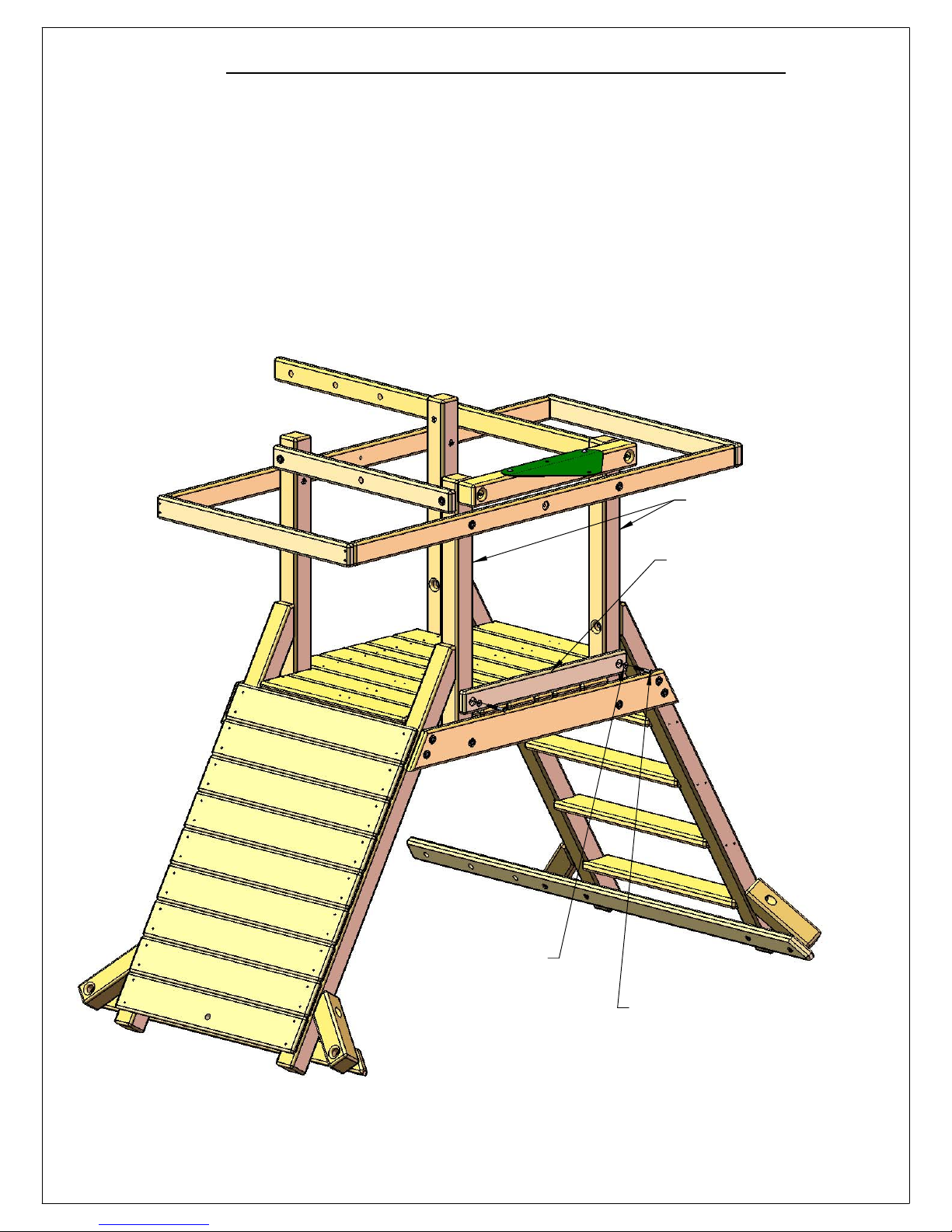
STEP 20: REAR BOTTOM PANEL BOARD
45
1: LOCATE THE 2 X 4 X 33" REAR BOTTOM PANEL BOARD.
2: PLACE THE REAR BOTTOM PANEL BOARD ON TOP OF THE DECK BOARDS AGAINST THE
OUTSIDE OF THE RIGHT CORNER POSTS. THE COUNTERBORED HOLES IN THE REAR
BOTTOM PANEL BOARD FACE OUT.
3: ATTACH THE REAR BOTTOM PANEL BOARD TO THE CORNER POSTS WITH TWO 3/8" X 31/2" LAG SCREWS AND TWO 3/8" WASHERS.
RIGHT CORNER POSTS
3/8" WASHER
2 X 4 X 33"
REAR BOTTOM
PANEL BOARD
(COUNTERBORED
HOLES FACE OUT)
3/8" X 3-1/2"
LAG SCREW
Page 56
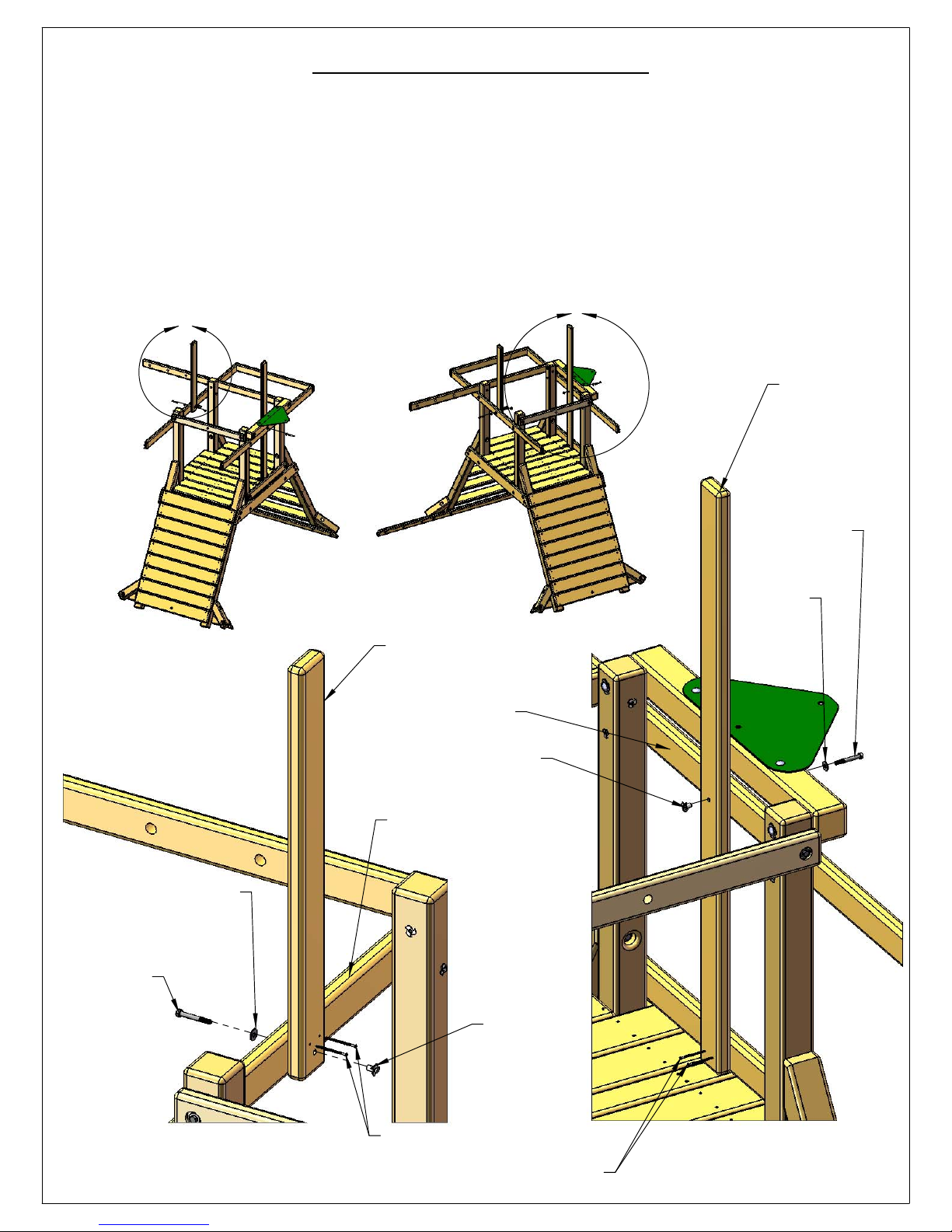
STEP 21: CENTER POSTS
46
1: LOCATE THE 2 X 4 X 34" FRONT CENTER POST AND THE 2 X 4 X 60" REAR CENTER POST.
2: (SEE DETAIL A) INSTALL A T-NUT INTO THE HOLE IN THE FRONT CENTER POST. LINE UP THE HOLE IN
THE FRONT CENTER POST WITH THE HOLE IN THE SIDE RAIL. ATTACH THE FRONT CENTER POST TO
THE SIDE RAIL WITH A 5/16" X 2-1/2" HEX BOLT AND A 5/16" WASHER. SQUARE THE FRONT CENTER
POST TO THE SIDE RAIL AND INSTALL TWO #8 X 2-1/2" WOOD SCREWS INTO THE PREDRILLED
HOLES.
3: (SEE DETAIL B) INSTALL A T-NUT INTO THE HOLE IN THE REAR CENTER POST. LINE UP THE HOLE IN
THE REAR CENTER POST WITH THE HOLE IN THE SIDE RAIL. ATTACH THE REAR CENTER POST TO THE
SIDE RAIL WITH A 5/16" X 2-1/2" HEX BOLT AND A 5/16" WASHER. SQUARE THE REAR CENTER POST
TO THE SIDE RAIL. INSTALL TWO #8 X 2-1/2" WOOD SCREWS INTO THE PREDRILLED HOLES AT THE
BOTTOM OF THE REAR CENTER POST.
A
B
2 X 4 X 60"
REAR
CENTER
POST
5/16" WASHER
5/16" X 2-1/2"
HEX BOLT
5/16" X 2-1/2"
HEX BOLT
5/16"
WASHER
2 X 4 X 34"
FRONT CENTER POST
SIDE RAIL
T-NUT
SIDE RAIL
DETAIL A
SCALE 1 : 8
#8 X 2-1/2"
WOOD
SCREWS
T-NUT
#8 X 2-1/2"
WOOD
SCREWS
DETAIL B
SCALE 1 : 10
Page 57
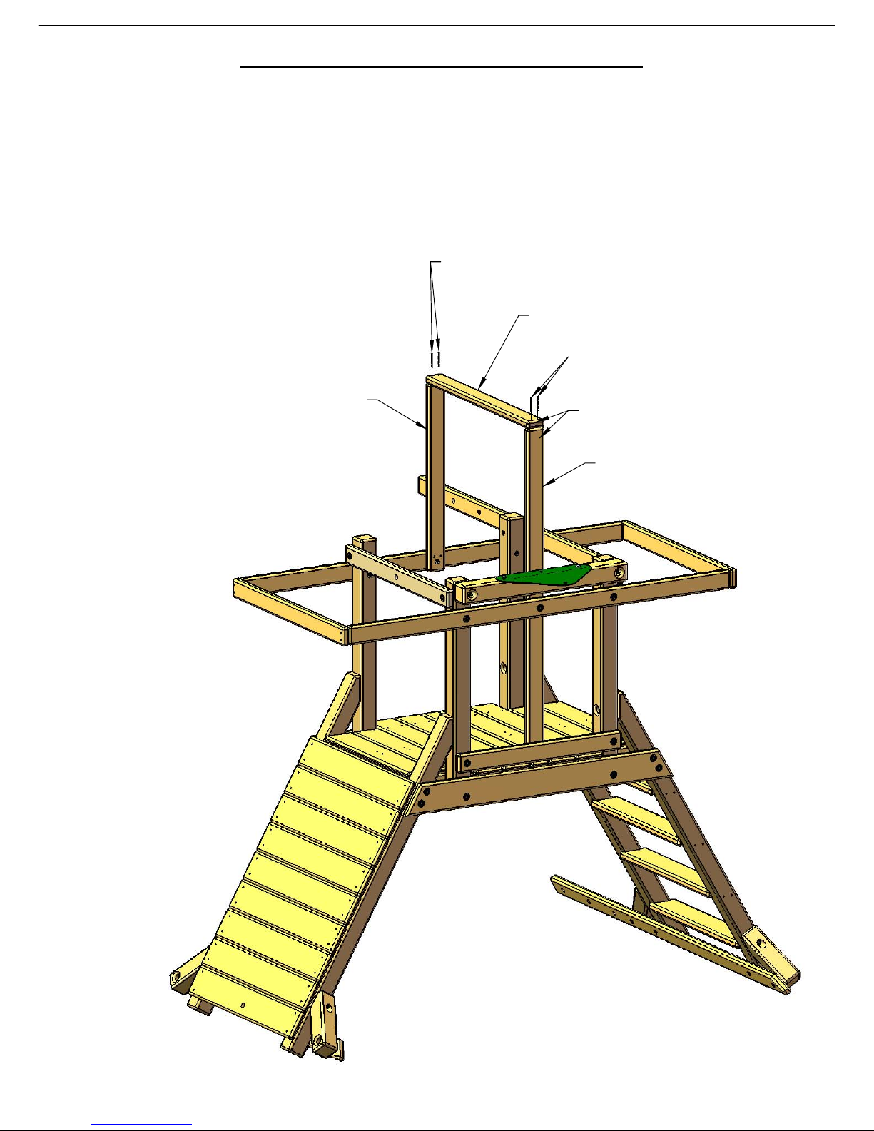
STEP 22: CENTER TARP BOARD
47
1: LOCATE THE 2 X 4 X 36" CENTER TARP BOARD.
2: PLACE THE CENTER TARP BOARD ON TOP OF THE FRONT CENTER POST AND REAR
CENTER POST. THE ENDS OF THE CENTER TARP BOARD SHOULD BE FLUSH TO THE SIDES OF
THE FRONT AND REAR CENTER POSTS.
3: ATTACH THE CENTER TARP BOARD TO THE CENTER POSTS WITH FOUR #8 X 2-1/2" WOOD
SCREWS.
#8 X 2-1/2" WOOD SCREWS
2 X 4 X 36" CENTER TARP BOARD
#8 X 2-1/2" WOOD SCREWS
FRONT CENTER POST
END FLUSH TO SIDE
REAR CENTER POST
Page 58

STEP 23: PANEL SLATS
48
1: LOCATE FOUR 2 X 3 X 28-1/2" PANEL SLATS.
2: SPACE THE PANEL SLATS AT THE DIMENSIONS SHOWN BELOW AGAINST THE SIDE RAIL
AND THE REAR BOTTOM PANEL BOARD. THE BOTTOM END OF EACH PANEL SLAT SHOULD
REST ON TOP OF THE DECK BOARDS.
3: ATTACH EACH PANEL SLAT TO THE SIDE RAIL AND REAR BOTTOM PANEL BOARD WITH
TWO #8 X 2-1/2" WOOD SCREWS.
2 X 3 X 28-1/2"
PANEL SLATS
#8 X 2-1/2"
WOOD SCREW
SIDE RAIL
REAR BOTTOM PANEL BOARD
(BEHIND SLATS)
2
1
16
1
16
#8 X 2-1/2"
WOOD SCREW
"
1
"
2
16
1
2"2
"
16
Page 59
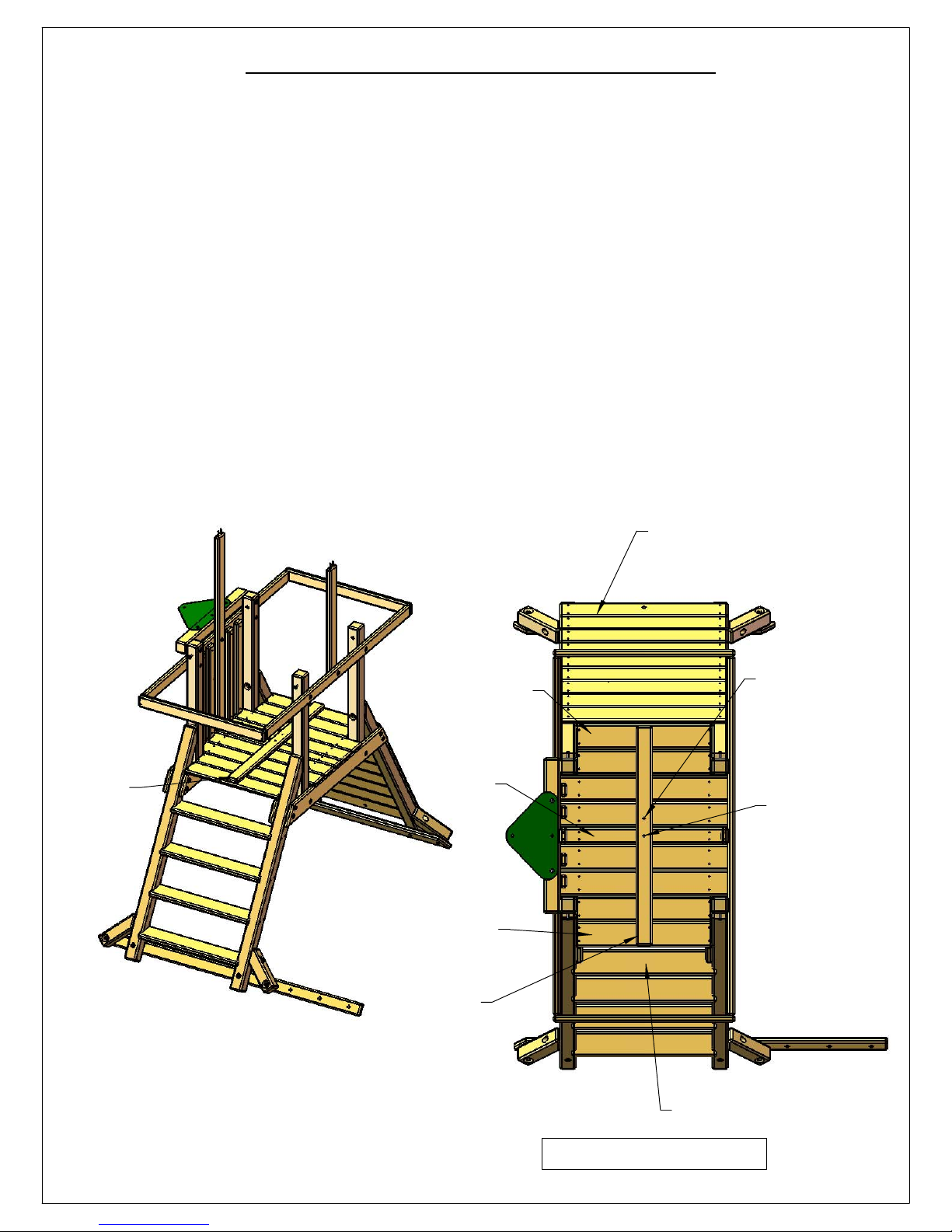
STEP 24: CENTER DECK SUPPORT
49
1: LOCATE THE 2 X 4 X 47" CENTER DECK SUPPORT.
2: YOU ARE GOING TO USE THE CENTER DECK SUPPORT HOLES AS A TEMPLATE IN THIS
STEP TO DRILL HOLES THROUGH TWO DECK BOARDS.
3: PLACE THE 2 X 4 X 47" CENTER DECK SUPPORT CENTERED BETWEEN THE CORNER POSTS
ON TOP OF THE DECK BOARDS. THE MIDDLE HOLE SHOULD BE CENTERED OVER THE
CENTER DECK BOARD. THE OTHER HOLE SHOULD LIE OVER THE TOP OF THE DECK BOARD
THAT IS TOWARDS THE ROCK WALL.
4: HOLD THE CENTER DECK SUPPORT DOWN WITH YOUR KNEE OR HAVE AN ASSISTANT
HOLD THE BOARD AGAINST THE DECK WHILE YOU DRILL HOLES.
5: DRILL THE CENTER HOLE FIRST WITH A 3/8" DIAMETER DRILL BIT THROUGH THE CENTER
DECK BOARD. PLACE A 3/8" X 3-1/2" CARRIAGE BOLT INTO THE HOLE.
6: DRILL THE OTHER HOLE SECOND WITH A 3/8" DIAMETER DRILL BIT THROUGH THE HOLE
TOWARDS THE ROCK WALL.
7: REMOVE THE CENTER DECK SUPPORT AND THE CARRIAGE BOLT FROM THE DECK
BOARDS.
2 X 4 X 47"
CENTER
DECK
SUPPORT
DECK SPACER
CENTER
DECK
BOARD
DECK SPACER
2 X 4 X 47"
CENTER DECK
SUPPORT
ROCK WALL
DRILL THIS HOLE
SECOND THROUGH
THE DECK BOARD
THAT IS TOWARDS
THE ROCK WALL.
CENTER THIS
HOLE OVER THE
CENTER DECK
BOARD. THEN
DRILL THIS HOLE
FIRST THROUGH
THE CENTER
DECK BOARD.
TOP STEP OF LADDER.
THIS IS THE TOP VIEW LOOKING
DOWN OVER THE DECK.
Page 60
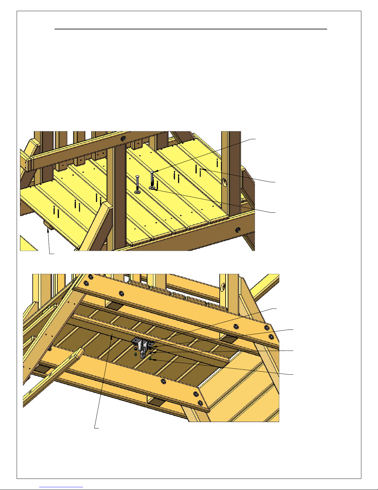
STEP 25: CENTER DECK SUPPORT AND HANGER
50
1: PLACE A 3/8" X 3-1/2" CARRIAGE BOLT THROUGH A TORQUE WASHER. PLACE THE
CARRIAGE BOLT INTO A 3/8" HOLE IN THE TOP OF THE DECK. HAMMER THE CARRIAGE
BOLT HEAD TO SET THE TORQUE WASHER TEETH INTO THE DECK BOARDS. REPEAT THIS
PROCESS FOR THE OTHER HOLE YOU DRILLED IN THE DECK.
2: LINE UP THE HOLES IN THE CENTER DECK SUPPORT WITH THE CARRIAGE BOLTS UNDER
THE DECK. PLACE THE IRON DUCTILE SWING HANGER OVER THE END OF THE CARRIAGE
BOLTS. SECURE THE SWING HANGER TO THE CARRIAGE BOLTS WITH 3/8" LOCK NUTS AND
3/8" WASHERS. PLACE BOLT CAPS OVER ANY EXPOSED THREADS.
3: GO TO THE TOP OF THE DECK AND SECURE EACH DECK BOARD WITH PREDRILLED
HOLES TO THE CENTER DECK SUPPORT WITH TWO #8 X 2" WOOD SCREWS.
3/8" X 3-1/2"
CARRIAGE BOLT
#8 X 2" WOOD SCREW
CENTER DECK SUPPORT UNDERNEATH DECK
TORQUE WASHER
IRON DUCTILE
SWING HANGER
3/8" WASHER
3/8" LOCK NUT
BOLT CAP
CENTER DECK SUPPORT
Page 61
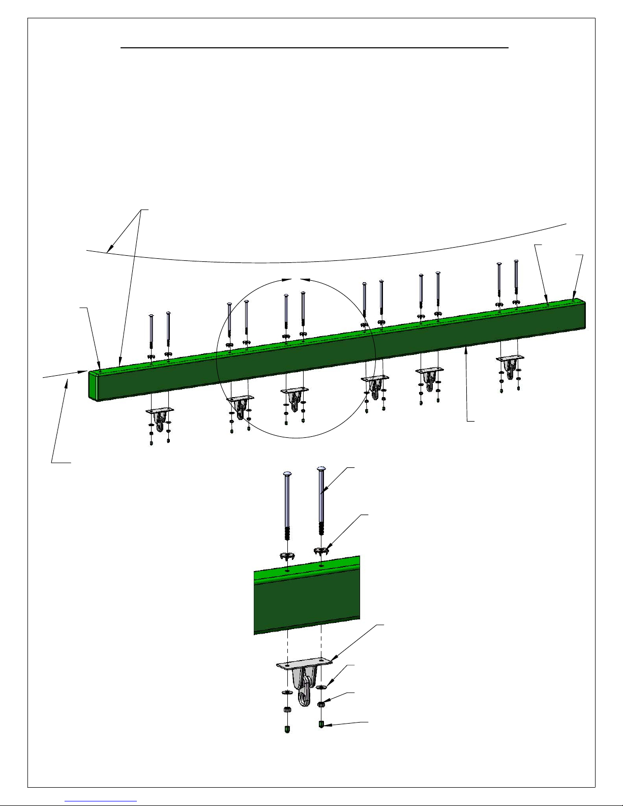
STEP 26: IRON DUCTILE SWING HANGERS
51
1: SIGHT DOWN THE LENGTH OF YOUR 4 X 6 X 108" SWING BEAM. IF THE TOP SURFACE OF
THE BEAM IS BOWED DOWN THEN TURN IT OVER SO THE BOW IS UP.
2: PLACE 3/8" X 6-1/2" CARRIAGE BOLTS WITH TORQUE WASHERS INTO THE HOLES SHOWN
BELOW TO ATTACH THE IRON DUCTILE SWING HANGERS. USE A HAMMER TO SET THE
TEETH OF EACH TORQUE WASHER INTO THE TOP OF THE SWING BEAM.
3: PLACE AN IRON DUCTILE SWING HANGER OVER THE ENDS OF THE CARRIAGE BOLTS.
FASTEN THE SWING HANGER TO THE SWING BEAM WITH 3/8" LOCK NUTS AND 3/8"
WASHERS. PLACE BOLT CAPS OVER ANY EXPOSED THREADS. REPEAT THIS PROCESS FOR
THE REMAINING FIVE SWING HANGERS.
IF TOP SURFACE OF BEAM IS BOWED DOWN LIKE
THIS THEN TURN IT OVER SO THE BOW FACES UP.
EMPTY
HOLES
A
EMPTY
HOLE
4 X 6 X 108"
SWING BEAM
SIGHT ALONG END OF BEAM
LOOKING IN THE DIRECTION
OF THE ARROW SHOWN FOR
A BOW IN THE SWING BEAM.
3/8" X 6-1/2"
CARRIAGE BOLT
TORQUE WASHER
IRON DUCTILE SWING HANGER
3/8" WASHER
3/8" LOCK NUT
BOLT CAP
DETAIL A
SCALE 1 : 7
Page 62

STEP 27: ATTACH SWING LEGS TO BRACKET
52
1: PLACE EACH SWING LEG INSIDE THE ANGLED PART OF THE SWING LEG BRACKET AS
SHOWN BELOW. THE TOP OF THE SWING LEG SHOULD BE FLUSH TO THE TOP EDGE OF THE
BRACKET AS SHOWN BELOW.
2: ATTACH EACH SWING LEG TO THE SWING LEG BRACKET WITH FOUR 3/8" X 3-1/2" LAG
SCREWS AND 3/8" WASHERS.
SWING LEG BRACKET
A
4 X 4 X 96"
SWING LEG
4 X 4 X 96"
SWING LEG
TOP OF THE SWING
LEG IS FLUSH TO THE
TOP EDGE OF THE
BRACKET.
DETAIL A
SCALE 1 : 5
3/8" X 3-1/2"
LAG SCREW
3/8" X 3-1/2"
LAG SCREW
3/8" WASHER
3/8" WASHER
Page 63
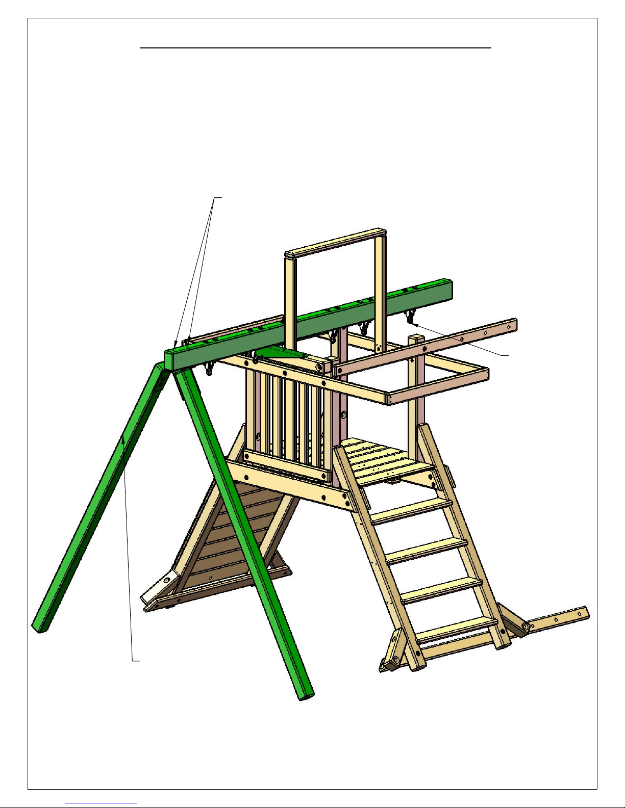
STEP 28: REST SWING BEAM ON FORT
53
*TWO PEOPLE ARE REQUIRED FOR THIS STEP
1: LAY THE SWING BEAM ACROSS THE FORT AND POSITION THE SWING LEGS UNDERNEATH
THE END OF THE BEAM. NOTE THE END OF THE SWING BEAM WITH TWO EMPTY HOLES WILL
BE POSITIONED OVER THE LEGS.
2: LINE UP THE PREDRILLED HOLES IN THE SWING BEAM WITH THE HOLES IN THE SWING LEG
BRACKET. THE IRON DUCTILE SWING HANGERS SHOULD BE FACING DOWN.
TWO EMPTY HOLES ON THIS
END OF SWING BEAM.
SWING
HANGERS
FACE
DOWN.
SWING LEGS AND
SWING LEG
BRACKET ASSEMBLY
Page 64
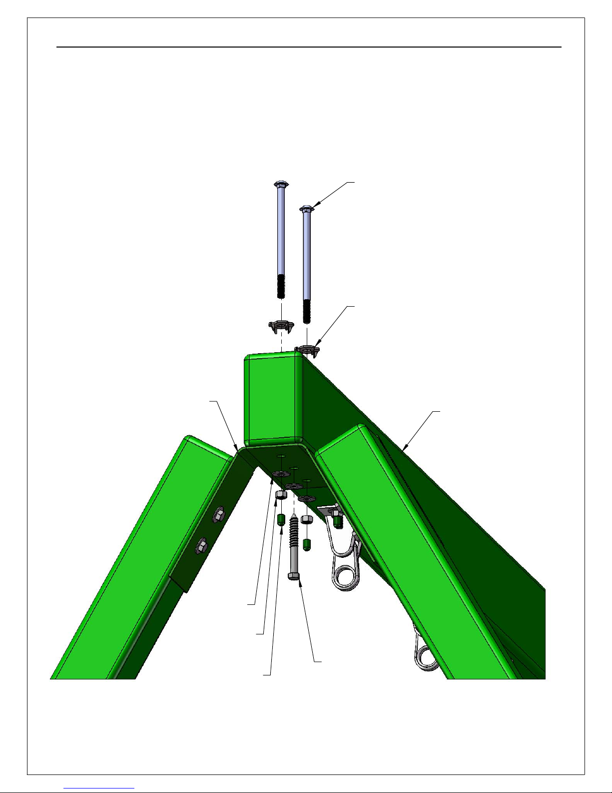
STEP 29: ATTACH SWING BEAM TO SWING BEAM LEGS
54
1: FASTEN THE SWING BEAM TO THE SWING LEG BRACKET WITH 3/8" X 6-1/2" CARRIAGE
BOLTS AND TORQUE WASHERS ON TOP OF THE SWING BEAM AND 3/8" LOCK NUTS WITH
WASHERS UNDERNEATH. USE BOLT CAPS TO COVER ANY EXPOSED THREADS.
2: FASTEN THE CENTER HOLE IN THE SWING LEG BRACKET TO THE SWING BEAM WITH A
3/8" X 3-1/2" LAG SCREW AND A 3/8" WASHER.
3/8" X 6-1/2" CARRIAGE BOLT
TORQUE WASHER
SWING LEG BRACKET
3/8" WASHER
3/8" LOCK NUT
BOLT CAP
SWING BEAM
3/8" X 3-1/2"
LAG SCREW
WITH 3/8" WASHER
Page 65
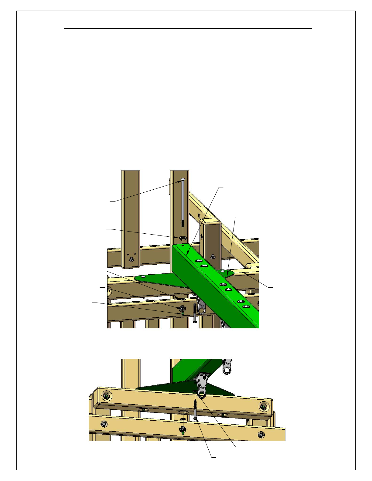
STEP 30: ATTACH SWING BEAM TO PLAY SET
55
*TWO PEOPLE ARE REQUIRED FOR THIS STEP
1: AFTER THE LEGS ARE ATTACHED, HAVE ONE PERSON ON THE GROUND PICK UP THE SWING BEAM BY THE
LEGS. THE SECOND PERSON WILL STAND ON THE PLAY SET DECK AND PICK UP THE SWING BEAM. THE
PERSON WITH THE LEG END WILL WALK AWAY FROM THE PLAY SET WHILE THE PERSON ON THE DECK LIFTS
THE SWING BEAM.
2: ONCE THE END OF THE SWING BEAM HAS BEEN REACHED BY THE PERSON ON THE DECK, PLACE THE END
OF THE SWING BEAM ON TOP OF THE TRIANGULAR SHAPED SWING BEAM PLATE. LINE UP THE HOLE IN THE
END OF THE SWING BEAM WITH THE MIDDLE HOLE IN THE SWING BEAM PLATE.
4: FASTEN THE SWING BEAM TO THE SWING BEAM PLATE AND SWING BEAM SIDE RAIL WITH A 3/8" X 9"
CARRIAGE BOLT WITH A TORQUE WASHER ON TOP AND A 3/8" LOCK NUT WITH 3/8" WASHER ON THE
BOTTOM. PLACE A BOLT CAP OVER THE EXPOSED THREADS ON THE BOTTOM OF THE 9" CARRIAGE BOLT.
5: MAKE SURE THE SWING BEAM IS CENTERED OVER THE OUTER HOLE IN THE SWING BEAM PLATE. TO
ACCOMPLISH THIS YOU MAY ALSO USE A SQUARE TO SQUARE THE SWING BEAM TO THE SWING BEAM SIDE
RAIL.
6: FASTEN THE SWING BEAM TO THE SWING BEAM PLATE FROM UNDERNEATH WITH A 3/8" X 3-1/2" LAG
SCREW AND A 3/8" WASHER.
3/8" X 9"
CARRIAGE
BOLT
TORQUE
WASHER
3/8" WASHER
3/8" LOCK NUT
BOLT CAP
SWING BEAM
SWING BEAM PLATE
SWING BEAM SIDE RAIL
3/8" WASHER
3/8" X 3-1/2" LAG SCREW
Page 66
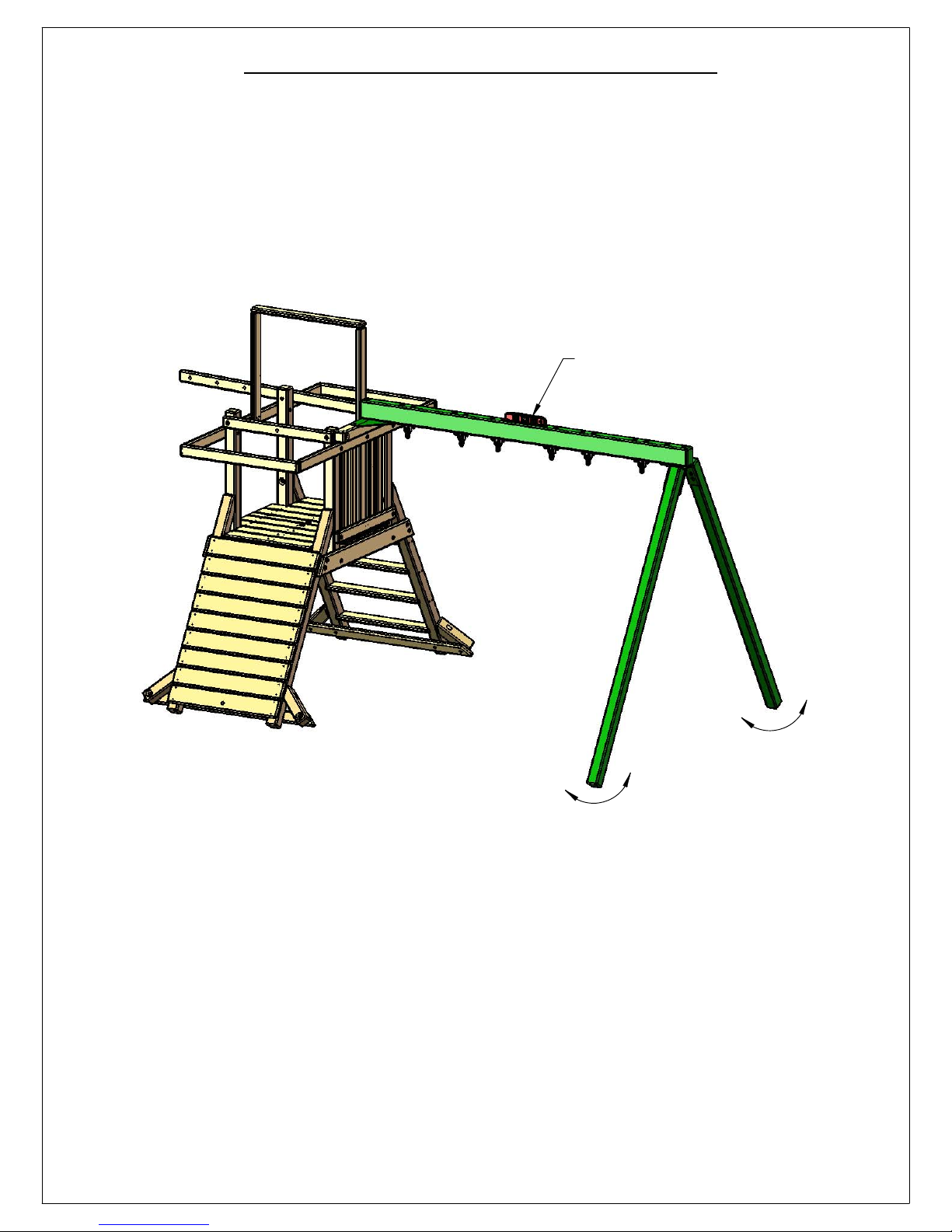
STEP 31: LEVEL THE SWING BEAM
56
1: PLACE A LEVEL ON TOP OF THE SWING BEAM AND ADJUST THE LEGS IN OR OUT AS
NEEDED TO MAKE THE SWING BEAM LEVEL.
LEVEL
Page 67

STEP 32: SWING LEG CROSS-MEMBER
57
1: POSITION THE 2 X 4 X 58" SWING LEG CROSS-MEMBER AGAINST THE OUTSIDE OF THE
SWING BEAM LEGS.
2: LEVEL THE CROSS-MEMBER AND CENTER THE HOLES OVER THE CENTER OF THE SWING
LEGS.
3: FASTEN THE CROSS-MEMBER TO THE SWING LEGS WITH 3/8" X 3-1/2" LAG SCREWS AND
3/8" WASHERS.
DETAIL A
SCALE 1 : 16
A
3/8" WASHERLEVEL
3/8" X 3-1/2"
LAG SCREW
2 X 4 X 58"
SWING LEG CROSS-MEMBER
Page 68
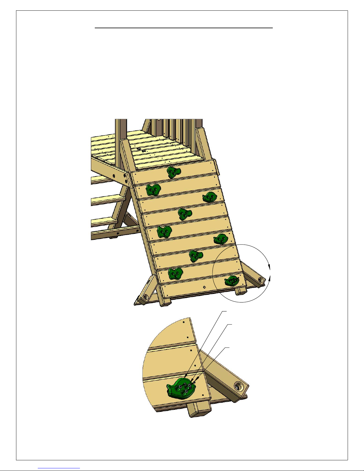
STEP 33: INSTALLING THE ROCKS
58
1: THE ROCKS SHOULD FOLLOW THE GENERAL STAGGERED LAYOUT SHOWN BELOW.
HOWEVER, A DIFFERENT LAYOUT MAY BE USED.
2: THE ROCKS INCLUDED WITH YOUR PLAY SET MAY VARY. THE #14 X 1-1/4" PAN HEAD
SCREWS AND 1/4" WASHERS INCLUDED WITH THE ROCKS WILL BE USED TO ATTACH THEM
TO THE ROCK WALL BOARDS.
DETAIL A
SCALE 1 : 8
A
ROCK
1/4" WASHER
#14 X 1-1/4"
PAN HEAD SCREW
Page 69
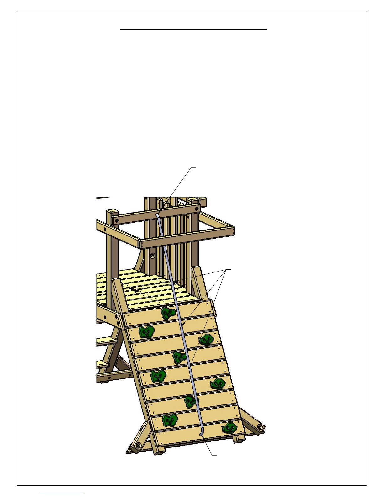
STEP 34: CLIMBING ROPE
59
1: THREAD THE END OF THE CLIMBING ROPE THROUGH THE HOLE IN THE ROCK WALL
ROPE SUPPORT. TIE A SECURE KNOT ON THE INSIDE OF THE ROCK WALL ROPE SUPPORT.
YOU MAY ADD UP TO 3 KNOTS ALONG THE LENGTH OF THE ROPE TO AID IN CLIMBING.
PLACE THE KNOTS ALONG THE ROPE IN POSITIONS SUITABLE FOR YOUR CHILD.
2: THREAD THE BOTTOM END OF THE ROPE THROUGH THE HOLE IN THE BOTTOM ROCK
WALL BOARD. PULL THE ROPE TIGHT AND TIE A SECURE KNOT BEHIND THE BOTTOM ROCK
WALL BOARD.
3: NOW GRAB THE ROPE AND ATTEMPT TO WRAP IT AROUND YOUR HAND. IF THE ROPE
WRAPS AROUND YOUR HAND IT IS TOO LOOSE. IF THE ROPE IS TOO LOOSE UNTIE THE
KNOT BEHIND THE ROCK WALL ROPE SUPPORT AND RETIE IT UNTIL YOU CAN NO LONGER
WRAP THE ROPE AROUND YOUR HAND.
TIE KNOT BEHIND THIS HOLE.
ADD UP TO 3 KNOTS TO AID IN CLIMBING.
TIE KNOT BEHIND THIS HOLE.
Page 70
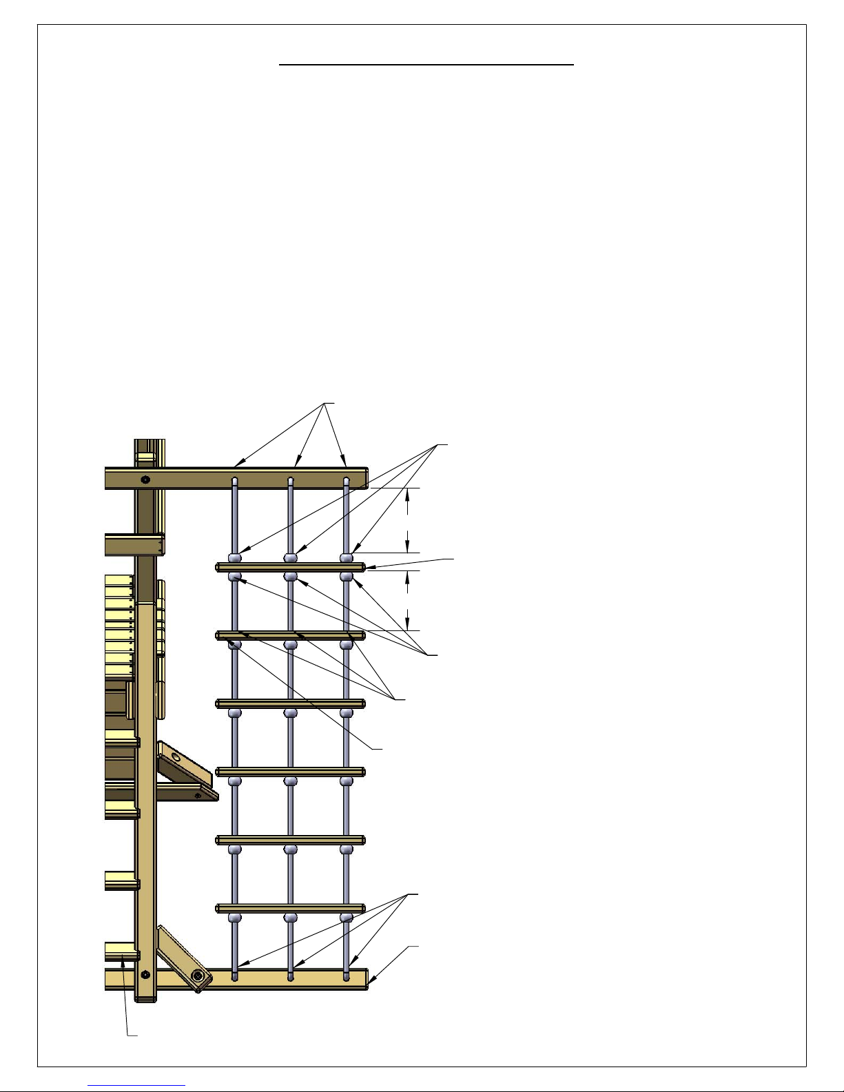
STEP 35: ROPE LADDER
60
1: FIND THE THREE ROPE LADDER ROPES. MAKE A KNOT IN THE END OF EACH ROPE AND THREAD THE FREE
END THROUGH THE BACK SIDE OF THE ROPE LADDER SUPPORT. PULL EACH ROPE TAUGHT.
2: MEASURE FROM THE BOTTOM OF THE ROPE LADDER SUPPORT DOWN 8 INCHES AND TIE A KNOT. THE TOP
OF THE KNOT SHOULD BE 8 INCHES BELOW THE BOTTOM OF THE ROPE LADDER SUPPORT. SLIDE EACH ROPE
THROUGH THE HOLES IN ONE ROPE LADDER RUNG.
SLIDE THE RUNG UP AGAINST THE BOTTOM OF THE KNOTS.
3: TIE THREE KNOTS BELOW THE ROPE LADDER RUNG.
4: MEASURE DOWN FROM THE BOTTOM OF THE ROPE LADDER RUNG 11 INCHES AND MAKE A MARK ON
THE ROPE WITH A PIECE OF TAPE OR A MARKER. THREAD ANOTHER ROPE LADDER RUNG ONTO THE ROPES.
5: WITH THE TOP OF THE RUNG EVEN WITH THE 11 INCH MARK TIE THREE KNOTS BELOW THE SECOND LADDER
RUNG.
6: REPEAT SUBSTEPS 4-5 FOR THE REMAINING ROPE LADDER RUNGS.
7: THREAD THE BOTTOM END OF EACH ROPE THROUGH THE HOLES IN THE ROPE LADDER RUNNER. GRAB
EACH ROPE AND ATTEMPT TO WRAP IT AROUND YOUR HAND. IF THE ROPE WRAPS AROUND YOUR HAND IT
IS TOO LOOSE. IF THE ROPE IS TOO LOOSE UNTIE THE KNOT BEHIND THE ROPE LADDER RUNNER AND RETIE IT
UNTIL YOU CAN NO LONGER WRAP THE ROPE AROUND YOUR HAND.
1) TIE A KNOT IN EACH ROPE AND THREAD THEM
THROUGH THE BACK SIDE OF THE ROPE LADDER
SUPPORT.
2) MEASURE DOWN 8" BELOW
THE BOTTOM OF THE ROPE LADDER
SUPPORT AND TIE 3 KNOTS. TOP OF
EACH KNOT SHOULD LIE AT THE 8"
MARK.
8"
2.1) SLIDE A ROPE LADDER RUNG
AGAINST THE THREE KNOTS.
11"
3) TIE THESE THREE KNOTS
BELOW THE ROPE LADDER RUNG.
4) MEASURE DOWN 11" BELOW THE
ROPE LADDER RUNG AND PLACE
TAPE ON THE ROPE OR MARK WITH A PEN.
5) SLIDE THE NEXT ROPE LADDER RUNG UP
TO THE MARKS OR TAPE. TIE THREE KNOTS
UNDER THE ROPE LADDER RUNG.
6) REPEAT 4 & 5 FOR REMAINING ROPE
LADDER RUNGS.
7) TIE KNOTS ON BACK SIDE OF ROPE LADDER RUNNER
ROPE LADDER RUNNER
THIS VIEW IS AS IF YOU ARE STANDING IN FRONT OF THE LADDER STEPS.
Page 71
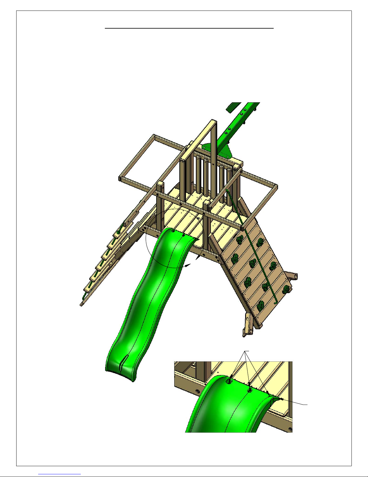
STEP 36: INSTALLING THE SLIDE
61
1: PLACE THE SLIDE IN THE OPENING AT THE LEFT SIDE OF THE PLAY SET.
2: THE STEPPED END WILL REST ON TOP OF THE DECK BOARDS.
3: ATTACH THE SLIDE TO THE DECK BOARDS WITH THREE #14 X 1-1/4" PAN HEAD SCREWS.
YOU MAY PREDRILL 1/8" HOLES THROUGH THE CENTER OF THE POCKETS IN THE SLIDE IF
YOU WISH.
A
#14 X 1-1/4" PAN HEAD SCREWS
STEPPED
END RESTS
ON TOP
OF DECK.
DETAIL A
SCALE 1 : 12
Page 72
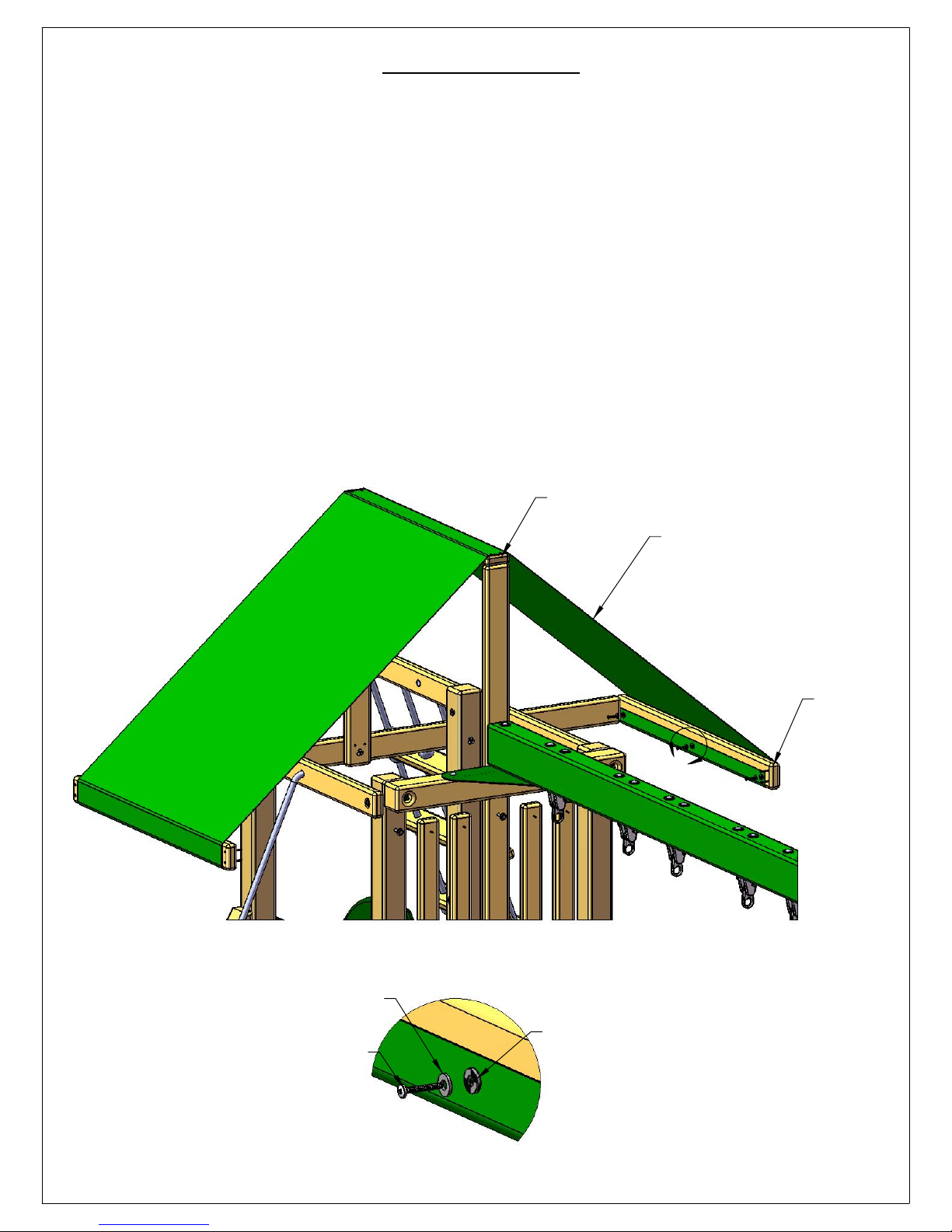
STEP 37: TARP
62
1: LAY THE TARP OVER THE TOP OF THE CENTER TARP BOARD AND MAKE SURE THE HEM
SIDE FACES DOWN.
2: WRAP EACH END OF THE TARP AROUND THE END OF THE TARP BOARDS INTO THE
INSIDE. IT MAY HELP TO HAVE A HELPER ON ONE SIDE WHILE YOU DO THIS SO THAT YOU
CAN MAKE THE ENDS OF THE TARP OVERLAP THE TARP BOARD EVENLY ON EACH END.
3: ONCE BOTH ENDS ARE WRAPPED EVENLY, MARK THE LOCATIONS OF THE GROMMETS
ONTO THE TARP BOARD ON ONE END ONLY. LET THE TARP END HANG DOWN AND DRILL
1/8" HOLES AT THE MARKS 1" DEEP.
4: FASTEN THE END OF THE TARP TO THE TARP BOARD USING THE HOLES YOU DRILLED WITH
#14 X 1-1/4" PAN HEAD SCREWS AND 1/4" WASHERS.
5: GO TO THE OTHER SIDE OF THE TARP AND WRAP THE END AROUND THE TARP BOARD
KEEPING THE TARP TIGHT. MAKE MARKS THROUGH THE GROMMETS ONTO THE TARP
BOARD. LET THE TARP END HANG DOWN AND DRILL 1/8" HOLES AT THE MARKS 1" DEEP.
6: FASTEN THE END OF THE TARP TO THE TARP BOARD USING THE HOLES YOU DRILLED WITH
#14 X 1-1/4" PAN HEAD SCREWS AND 1/4" WASHERS.
CENTER TARP BOARD
1/4" WASHER
TARP
36" X 117"
TARP
BOARD
A
DETAIL A
SCALE 1 : 3
#14 X 1-1/4"
PAN HEAD SCREW
GROMMET
Page 73
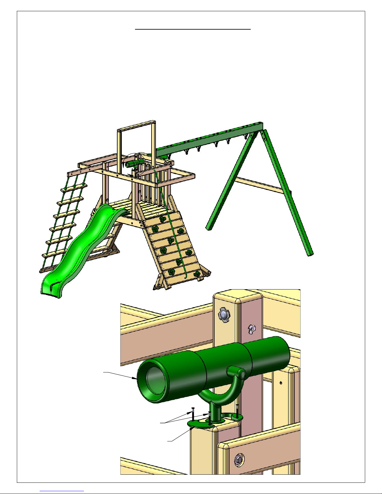
STEP 38: TELESCOPE
63
1: USE THE 1-1/4" WOOD SCREWS PROVIDED WITH THE TELESCOPE TO FASTEN ONE OF THE
HALF-CIRCLE SHAPED TELESCOPE BRACKETS ON TOP OF THE CORNER POST ABOVE THE
SLIDE.
2: PLACET THE TELESCOPE STAND AND TELESCOPE INTO THE SLOT OF THE TELESCOPE
BRACKET.
3: FASTEN THE REMAINING HALF-CIRCLE SHAPED TELESCOPE BRACKET TO THE OPPOSITE
SIDE THAT THE FIRST TELESCOPE BRACKET WAS INSTALLED. USE THE 1-1/4" WOOD SCREWS
PROVIDED WITH THE TELESCOPE TO ATTACH THE TELESCOPE BRACKET.
A
TELESCOPE
1-1/4" WOOD SCREWS
PROVIDED WITH TELESCOPE
HALF CIRCLE TELESCOPE BRACKET
DETAIL A
SCALE 1 : 4
Page 74
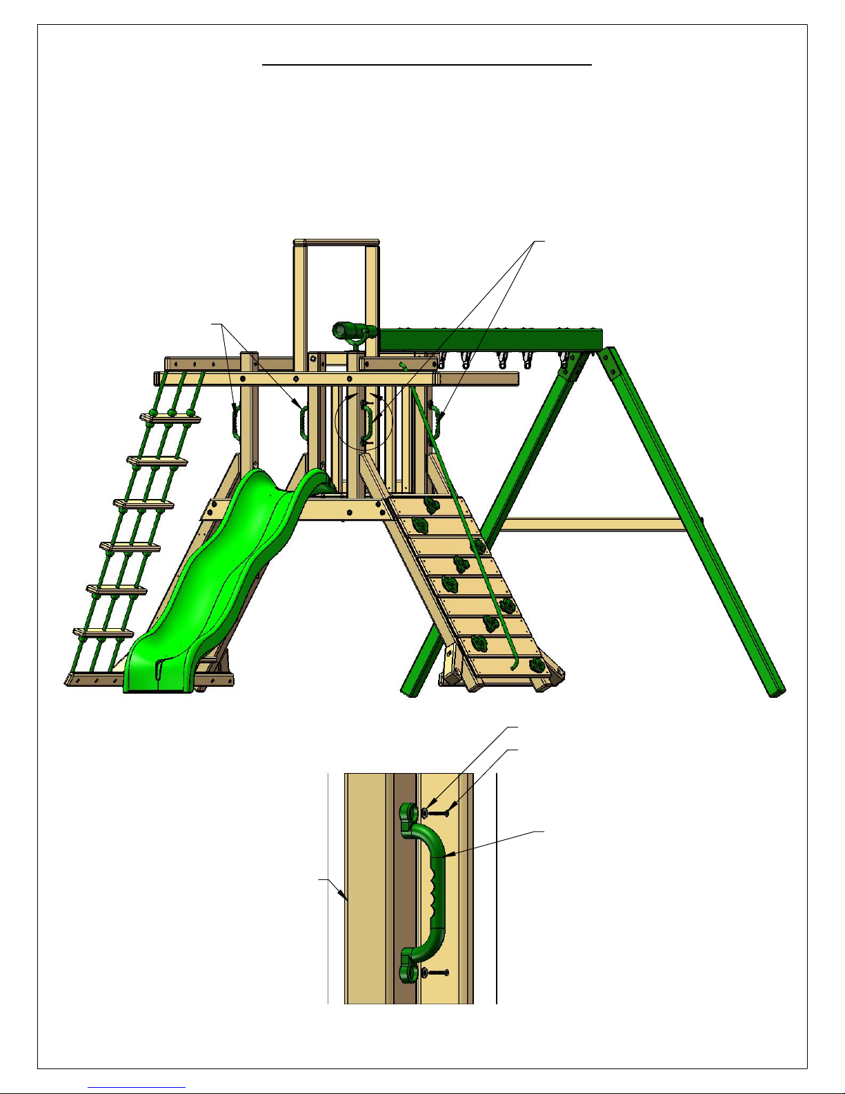
STEP 39: SAFETY HANDLES
64
1: LOCATE THE PLASTIC SAFETY HANDLES (2 BAGS). EACH BAG SHOULD CONTAIN TWO
SAFETY HANDLES WITH HARDWARE TO ATTACH THEM.
2: PLACE THE SAFETY HANDLES ON THE OUTSIDE OF THE CORNER POSTS ABOVE THE ROCK
WALL AND LADDER. ADJUST THE HANDLES UP OR DOWN TO SUIT THE NEEDS OF YOUR
CHILD. CENTER THE HOLES IN THE HANDLE IN THE MIDDLE OF EACH CORNER POST.
3: ATTACH EACH SAFETY HANDLE TO A CORNER POST WITH THE PAN HEAD SCREWS AND
WASHERS PROVIDED.
PLASTIC
SAFETY
PLASTIC
SAFETY
HANDLES
ABOVE LADDER
A
HANDLES
ABOVE ROCK WALL.
CORNER POST
DETAIL A
SCALE 1 : 6
WASHER
PAN HEAD SCREW
PLASTIC
SAFETY
HANDLE
Page 75
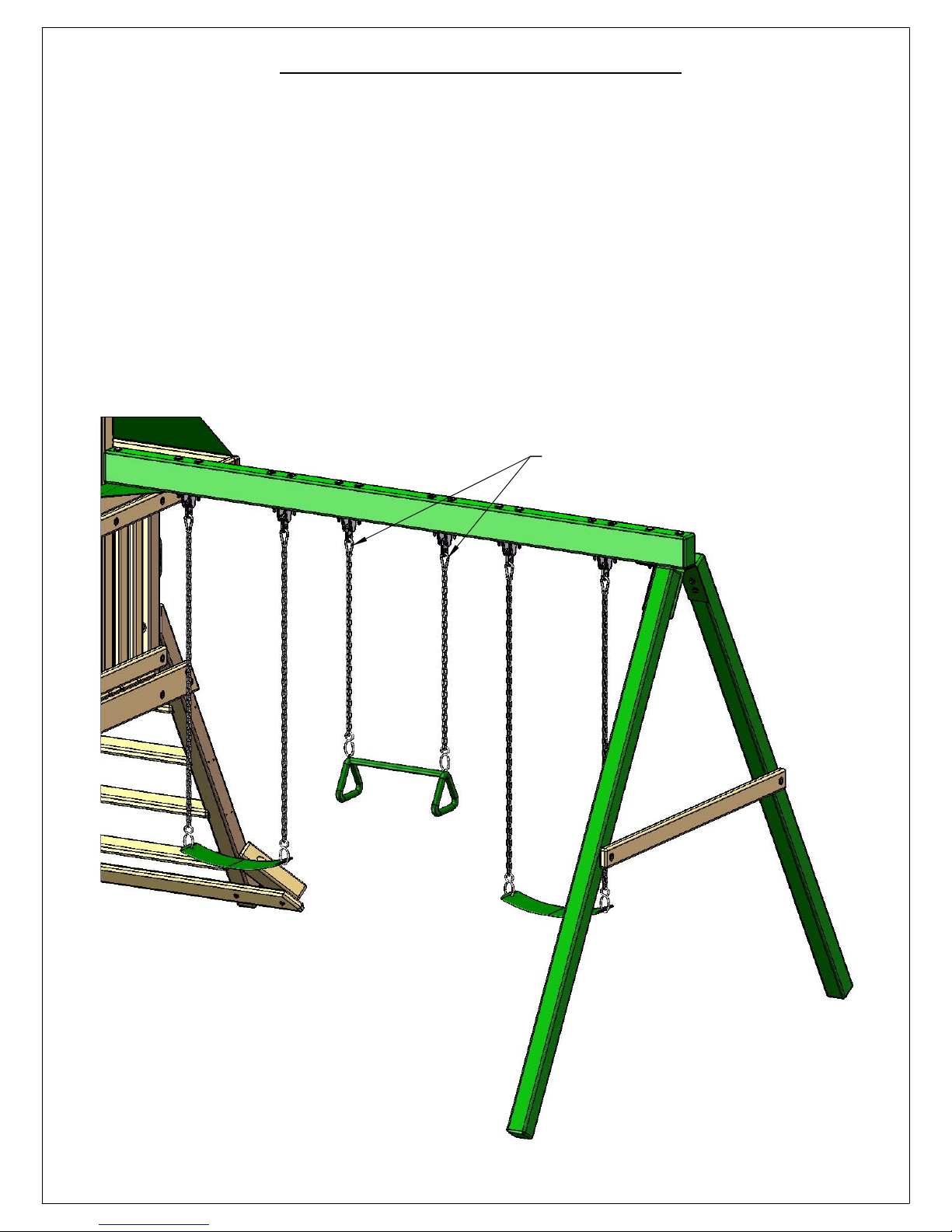
STEP 40: HANGING SWINGS
65
1: CLIP EACH OF THE SPRING CLIPS ONTO THE IRON DUCTILE SWING HANGERS, THEN CLIP
ONTO THE SWING CHAINS.
2: USE THE CLIPS TO ADJUST THE HEIGHT OF THE SWING BY CLIPPING ON HIGHER OR
LOWER LINKS.
3: COUNT BACK THE SAME NUMBER OF LINKS ON THE OPPOSITE SIDE TO ENSURE THE
SWING IS LEVEL, AND ADJUST TO FIT YOUR NEEDS.
4: ANY EXCESS CHAIN MAY BE LOOPED AND CLIPPED INTO THE SPRING CLIPS.
SPRING CLIPS
Page 76
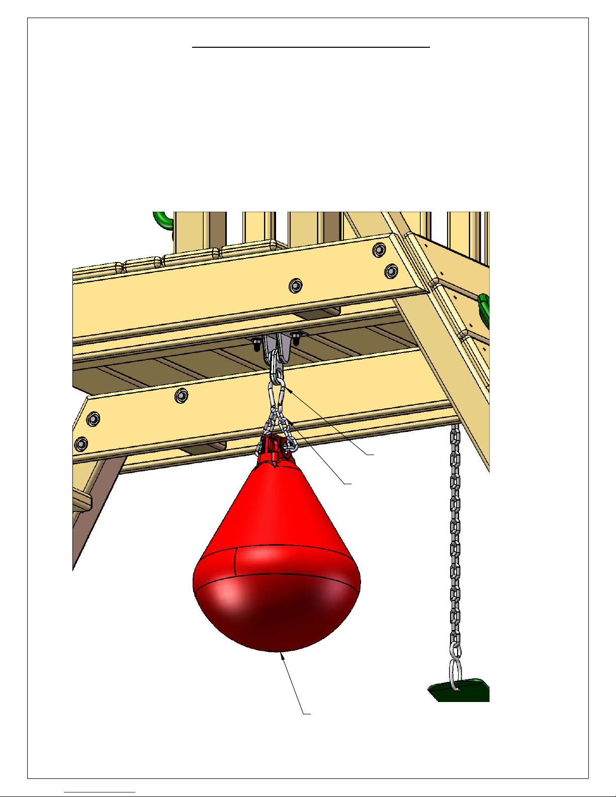
STEP 41: PUNCHING BALL
66
1: PLACE THE 1 FOOT SECTION OF CHAIN THROUGH THE HOLE IN THE PUNCHING BALL.
2: SNAP THE SPRING CLIP ONTO THE IRON DUCTILE SWING HANGER UNDER THE PLAY SET
DECK.
3: SNAP THE ENDS OF THE CHAIN ONTO THE SPRING CLIP.
SPRING CLIP
1 FOOT CHAIN
PUNCHING BALL
Page 77
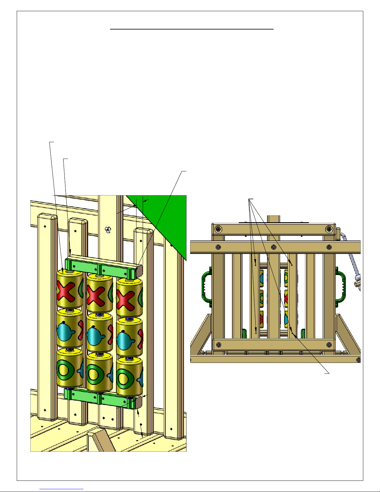
STEP 42: TIC TAC TOE PANEL
67
1: ASSEMBLE THE TIC TAC TOE PANEL ACCORDING TO THE INSTRUCTIONS IN THE BOX. IGNORE STEPS 6 AND
7 IN THE INSTRUCTIONS.
2: ATTACH THE TWO 1-3/8" X 1-5/8" X 10-1/2"L TIC TAC TOE BOARDS TO THE GREEN PLASTIC BRACKET WITH
THE 1" LONG PHILLIPS HEAD SCREWS PROVIDED WITH IN THE TIC TAC TOE BOX. IMPORTANT: MAKE SURE THE
TIC TAC TOE BOARD IS MOUNTED TO THE GREEN BRACKET OBSERVING THE 1-5/8" DIMENSIONS SHOWN
BELOW.
3: CENTER THE UNIT ON THE PANEL SLATS AS SHOWN.
4: MOUNT THE LOWER TIC TAC TOE BOARD 4" ABOVE THE DECK. ATTACH TIC TAC TOE BOARD TO THE
PANEL SLATS FROM THE OUTSIDE WITH #8 X 2-1/2" WOOD SCREWS. IT WILL BE HELPFUL TO HAVE AN
ASSISTANT HOLD THE TIC TAC TOE PANEL AGAINST THE PANEL SLATS WHILE YOU GO ON THE OUTSIDE AND
PREDRILL 1/16" HOLES THROUGH THE PANEL SLATS AND PARTIALLY INTO THE TIC TAC TOE BOARDS. THESE
HOLES WILL MAKE IT EASIER TO ATTACH THE TIC TAC TOE TO THE PANEL SLATS AND WILL LESSEN THE
POSSIBILITY OF SPLITTING A BOARD.
ASSEMBLED TIC TAC TOE PANEL
1-3/8" X 1-5/8" X 10-1/2"
TIC TAC TOE BOARDS
(TOP AND BOTTOM)
GREEN PLASTIC BRACKET
PREDRILL HOLES FROM OUTSIDE.
1 5/8"
#8 X 2-1/2" WOOD SCREWS
VIEW FROM OUTSIDE PLAY SET DECK
1 5/8"
VIEW FROM PLAY SET DECK
4"
Page 78
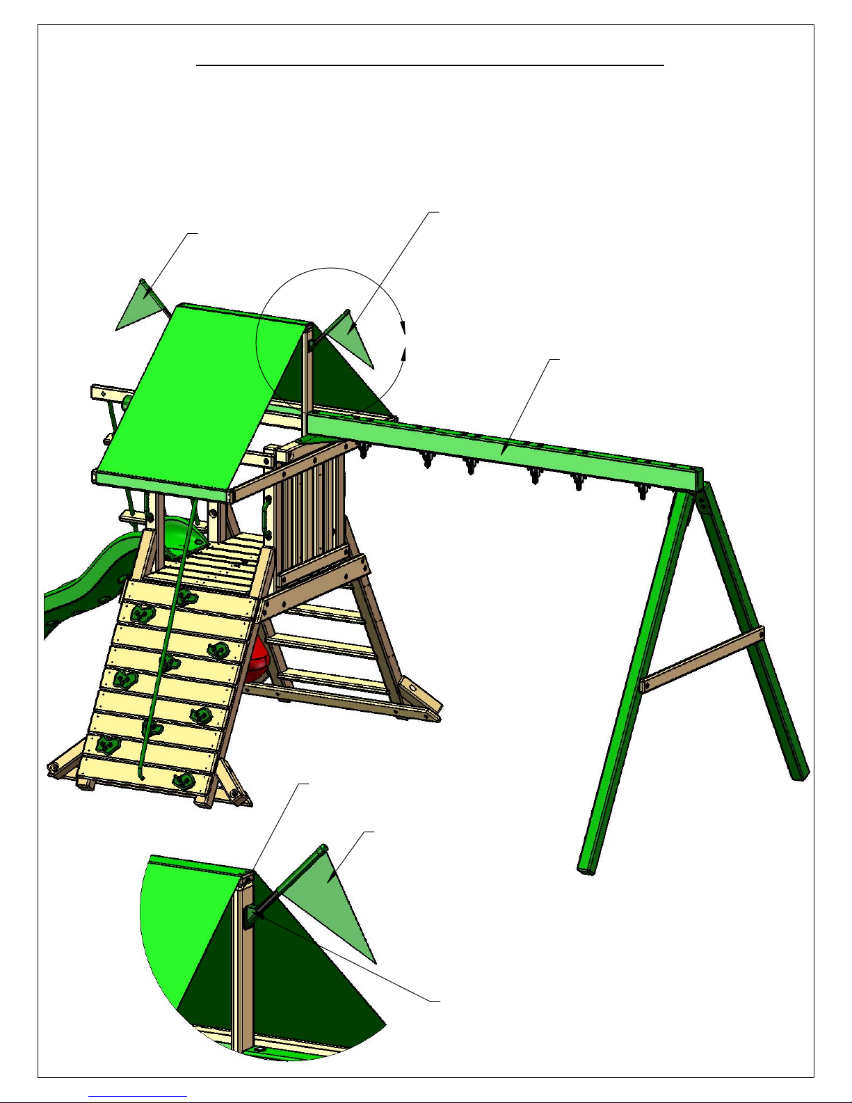
STEP 43: FLAG KIT AND NAME PLATE
68
1: ATTACH THE PLASTIC FLAG BASE ONTO THE OUTSIDE OF THE CENTER TARP SUPPORTS
WITH THE SCREWS PROVIDED IN THE FLAG KIT BAG.
2: ATTACH THE ALUMINUM NAME PLATE CENTERED ON THE FRONT OF THE SWING BEAM
WITH #8 X 1-1/4" WOOD SCREWS.
FLAG
FLAG
A
PLACE NAME PLATE HERE
AND SECURE WITH #8 X 1-1/4"
WOOD SCREWS.
CENTER TARP SUPPORT
FLAG
PLASTIC FLAG BASE
Page 79

STEP 44: GROUND STAKES
69
1: HAMMER A GROUND STAKE INTO THE EARTH NEXT TO EACH SWING LEG AT AN ANGLE.
DO NOT HOLD THE UPPER PORTION OF THE STAKE AFTER THE FIRST COUPLE OF HITS OR IT
MAY VIBRATE HARSHLY AGAINST YOUR HAND. IF THE TOP PART OF THE STAKE TWISTS
WHEN IT ENCOUNTERS A ROCK OR ROOT YOU MAY HAVE TO BEND THE TOP PORTION OF
THE STAKE AGAINST THE SWING LEG. FINALLY INSTALL THE SCREW AND WASHER.
2: ATTACH EACH GROUND STAKE TO THE SWING LEG WITH A #14 X 2" PAN HEAD SCREW
AND A 1/4" FENDER WASHER PROVIDED WITH THE GROUND STAKE.
SWING LEG
1/4" FENDER
WASHER
#14 X 2"
PAN HEAD SCREW
GROUND
STAKE
DETAIL A
SCALE 1 : 5
A
GROUND STAKES
 Loading...