

PlayActive JE118 Owner's Manual

• Suitable for 37~96 Months
• Maximum user weight: 30kg
• Adult assembly required
Please keep this manual for future reference as it contains important
information.
Before first time use, charge the battery for at least 4-6 hours.
OWNER'S MANUAL
with Assembly Instructions
Read and understand this entire manual before using!
CHILDREN'S
ELECTRIC TOY CAR
Products features may vary
from the picture above.
With remote control function
Use the vehicle on generally level ground ONLY!
caution
About Your New Vehicle
Thank you for your purchasing our products, we wants your child to enjoy this product for years to
come. Keep these points in mind as you read this guide:
FOR THE SAFETY OF YOUR CHILD, PLEASE READ ALL WARNINGS AND
ASSEMBLY/USE INSTRUCTIONS. KEEP THIS GUIDE FOR FUTURE REFERENCE.
• ADULT ASSEMBLY REQUIRED. The product contains small parts, which are for
adult assembly only. Keep children away when assembling.
• Always remove protective material and poly bags and dispose before assembly.
WARNING!
Suitable age:
37~96 months
6V4AH x1(Fuse: 7A) or 6V7AH x1(Fuse: 7A) or 6V10AH x1 (Fuse:7A)
Load Capacity:
Under 30KGS
Size of car:
118 x 81 x 67 CM
Speed:
3KM/H
3~5KM/H
Power way:
Charging type
Charger:
Input: depend on local voltage
Output: DC 6V500mA or DC6V1A
or DC12V1A
Average
battery life:
Approximately
300 times
Charge time:
8-12 Hours
Battery &
Fuse:
1WD
2WD
1WD
1WD
2WD
2WD
IMPORTANT
WARNING
This label means the information or assembly for One Wheel Drive version ONLY!
This label means the information or assembly for Two Wheels Drive version ONLY!
CHOKING HAZARD - Small parts.
Not suitable for children under 37
months.
VER:SMS-XX-EN-111212
6V7AH x1 (Fuse: 10A)
VER:SMS-JE118-EN-120503VER:SMS-JE118-EN-RC-120503

1
1
4
8
1
1
2
1
1
1
1
x1
x2
x3
x2
x1
x2
x1
x2
x4
x8
x3
x2
2
1
1
1
4
12
2
2
3
A
B
C
D
4
1
2
3
4
5
6
7
8
9
10
11
12
13
14
15
16
17
18
19
20
21
22
23
2
3
1
1
24
25
2
Parts List
PART
NO.
REMARKS
Assembly package
1WD
2WD
1WD
2WD
1WD
2WD
1WD
2WD
1WD
2WD
1WD
2WD
PART NAME
Q’ty (pcs)
Vehiclebody
Viewmirrors
Ø10Locknut
Ø10Washer
Seat
Ø5nut
Sidesupport
Steeringcolumn
Rearaxle
Steeringwheel
M5x35machinescrew
Drivingwheel
Wheel
Gearbox
Motorhood
Ø4x12flathead
screw
Ø10bushing
M5x16machinescrew
Windshield
Backrest
Charger
Capnut
Ø4x12roundheadscrew
Splitpin
Spanner
Ø10Washer
4pcsplacedonthefrontaxle,
4pcsplacedontherearaxle.
2pcsplacedonthefrontaxle,
2pcsplacedontherearaxle.
Placedonthesteeringwheel
Placedonthesteeringwheel
1pcslabeled“R”,1pcslabeled“L”
1PCSFORSPARE
Exhaust
Decorativestrip
M5x25machinescrew
Remotecontroller
1pcsplacedonthesteeringwheel,
1pcsplacedonthesteeringcolumn.
1
22
3
A
4
4
16
5
B
B
C
4
7
D
8
9
10
11
6
12
13
23
14
15
2
2
17
20
21
D
19
18
6
24
25
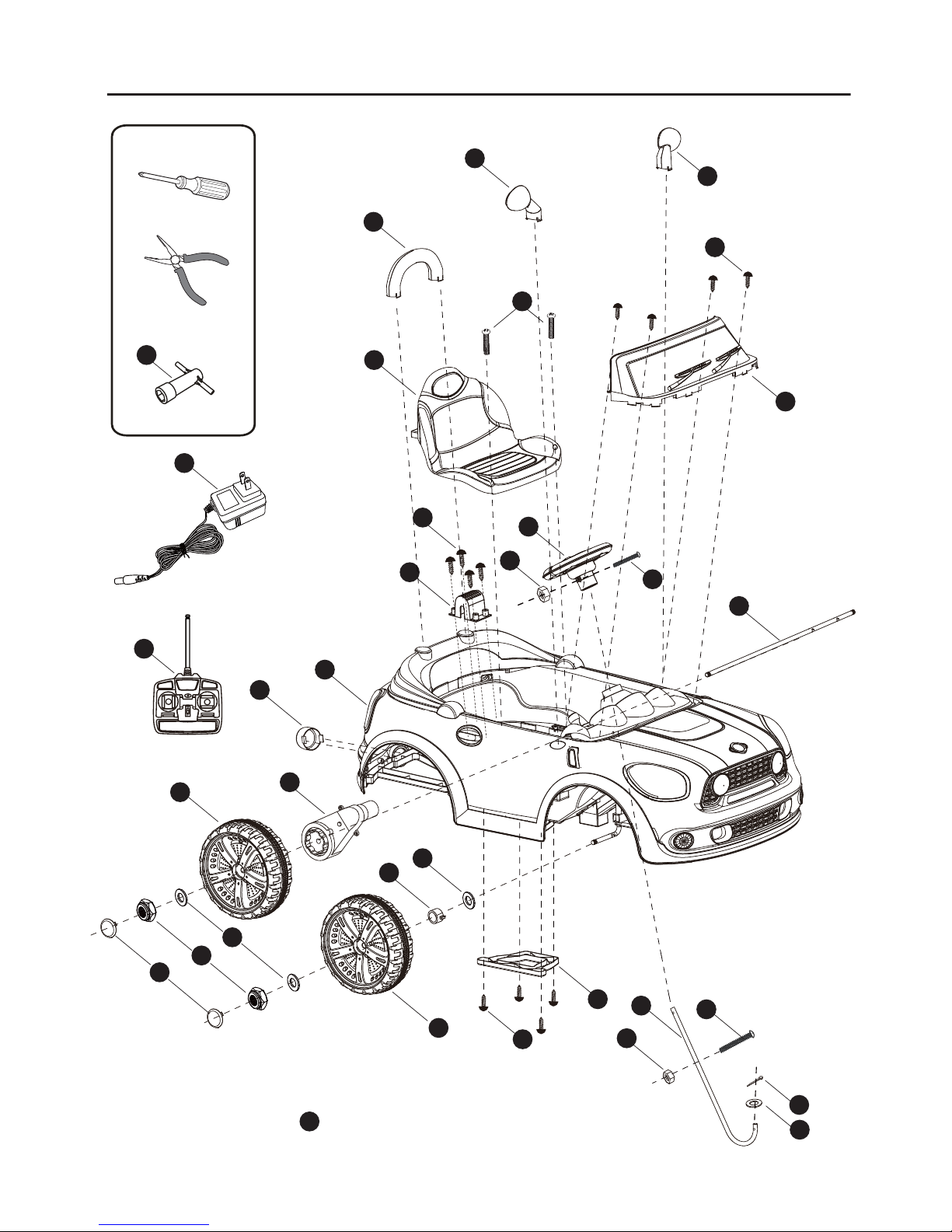
Tools Required
Screwdriver(not included)
Spanner
Pliers(not included)
Parts Diagram
NOTE: Some parts shown are assembled on both sides of vehicle
PART NOT SHOWN : Decorative strip x3
2
1
x4
Assembly Steps
• Your new vehicle requires adult assembly. Please set aside at least 40 minutes for
assembly. Children can be harmed by small parts, sharp edges and sharp points in the
vehicle's unassembled state. Care should be taken in unpacking and assembly of the
vehicle. Children should not handle parts, or help in assembly of the vehicle.
• Please identify all parts before assembly and save all packaging material until assembly
is complete to ensure that no parts are discarded.
• Assembly tool for need: screwdriver(provide for oneself) and spanner.
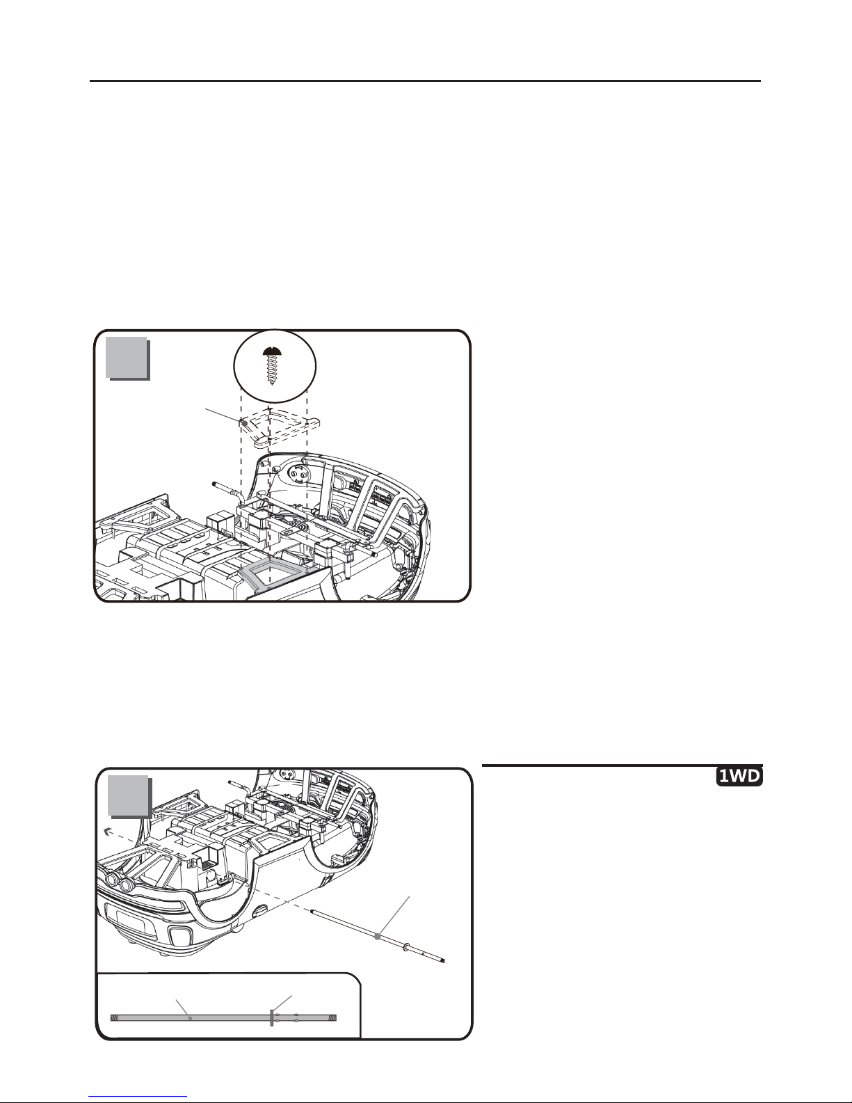
●
Remove all the parts from the rear
axle.
●
Slide a Ø10 washer onto the rear axle
from the longer end.
●
Insert the rear axle through the hole in
vehicle body.
Ø10 Washer
Rear axle
Rear axle
● Turn the vehicle body downside
up.
●
Fit the side support to the vehicle
body.
●
Insert four Ø4x12 round head
screws and tighten with a screwdriver.
● Repeat for the other side.
Ø4x12 round
head screw
Side support

3
Assembly Steps
2WD
2WD
● Turn the vehicle body downside up.
●
Remove all the parts from the rear axle.
●
Insert the rear axle through the hole in the
vehicle body.
Rear axle
Hint: An extra spanner has been provided to hold the Ø10 locknut on the other side
of the front axle while tightening the locknut on the other side.
● Fit the gear box onto the rear axle
from the left side (Standing at the rear of the
vehicle body). And make the motor on the
gear box pass through the hole in the vehicle
body.
● Fit the driving wheel onto the rear axle,
keep it match with the gear box.
● Fit a Ø10 washer onto the rear axle.
● Fit a Ø10 locknut to the end of the rear
axle.
● Insert the tabs on the hubcap into slots in
the driving wheel.
● Slide the gear box (standing at back of vehicle body) onto the rear axle. “R” labeled gear box should be fit
to the “R” side of vehicle body; “L” labeled gear box should be fit to “L” side of vehicle body.
● Slide the driving wheel onto rear axle, make it match with the gear box.
● Slide a
Ø
10 washer.
● Tighten the
Ø
10 locknut with a spanner.(Do not over tighten)
● Repeat this procedure to assemble the other driving wheel to the rear axle.
● Fit the hubcap to the driving wheel.
Driving wheel
Ø10
Locknut
Gear box
Rear
axle
Ø10
Washer
Hubcap
 Loading...