

Page 1
ToneMaster
TM
Tone Generator User Instructions
Part Numbers: TG210/TG220
Warning! Do not attach to live AC circuits. This could cause an extreme shock hazard and damage
the tone generator. To prevent damage to your tone generator always set the tone generator to
STATUS mode before connecting to any circuit.
FEATURES
• Four tone amplitude configurations: Half, Full, High-Powered Half and High-Powered Full
• Half amplitude is unbalanced for stronger tone on twisted pairs
• Three distinctly different tones selected from front panel
• Constant Amplitude tone over life of battery for 100% tone strength all the time
• Auto-off — tone turns off after 15 minutes; prevents having dead battery if left on
• Tone may be added in any mode — allows phone sets without monitor feature to pick up tone
• No power draw in continuity mode with leads open— no dead battery if left in continuity
• Polarity indicator for phone lines
• RJ jack allows use of modular cable without adapters
• Use as Talk Battery to test dry phone (unpowered) lines
Note: The RJ jumper cable that has been provided with the tone generator uses a uniquely-colored
no-fault modular connector that can be plugged into an RJ12 jack or RJ45 jack.
INSTRUCTIONS FOR USE
To send a tone for tracing
1. Move the slide switch on left side of tone generator to the TONE position for normal operation.
2. Connect the test lead(s) to a wire or both wires in a wired pair. Otherwise attach one lead to the wire
of a cable or attach one lead to one wire in paired wires being traced. A modular phone cable can be
used to connect the tone generator directly to a wall jack.
3. Press the TONE button briefly to turn on the tone. Press the TONE button to cycle through the different tone configurations.
4. Hold a tone tracer probe near the jack to hear each tone type as it is selected.
5. To turn off the tone, press and hold the TONE button until no LED’s are lit. After 15 minutes the tone generator will turn off
automatically.
6. To change the cadence, press the TONE CADENCE button to cycle through constant, warbling, high-frequency constant, and warbling high-frequency tones.
Application Hints:
• For long runs and when used with twisted pair cables, turning on the HIGH-POWERED mode increases the tone amplitude by over
700% but will also use more battery power.
• The normal amplitude mode uses the minimum battery power. Use the normal power amplitude setting if there is too much bleeding
of the tone into adjacent wires.
• For twisted pairs, connect the clips from the tone generator to the wires of separate pairs. Connecting to wires in the same pair will
result in a softer tone and tends to contain the tone within the cable. With softer tones, the tracer must nearly touch the end of the
cable to detect the tone. This is the case if the cable is terminated with a connector or a jack.
• To maximize the tone while tracing along a cable run, connect one lead of the tone generator to the wire or cable and the other end to
an earth ground (such as the case of an electrical box, electrical conduit, metallic water pipe or ground rod). If no ground is available,
do not connect the other lead to anything; let it dangle as near to the earth as possible.
• To block tone over-bleeding on coax cables, connect one lead to the center pin and the other lead to the ungrounded shield of the
cable.
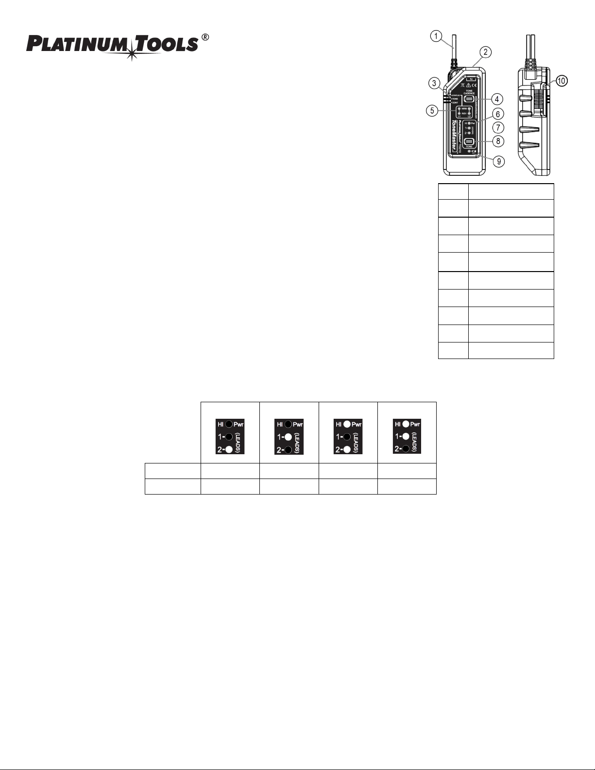
1 Test leads
2 RJ12 Jack
3 Test Mode
4 Cadence Button
5 Telephone Test Indicators
6 Tone Power Mode
7 Tone Lead Selection
8 Tone Button
9 Battery Level
10 Test Mode Switch
Normal Power Normal Power High Powered High Powered
Half Full Half Full Red Lead (1)
Black Lead (2) Full Full Full Full
Page 2
To check the status of a phone circuit
1. Move the slide switch on the left side of the tone generator to the STATUS position.
2. Connect the black lead to TIP and the red lead to RING or one lead to each wire of the pair if designation is unknown.
• If the NRM LED lights up, it means the polarity is correct and the black lead is connected to TIP.
• If the REV LED lights, then the leads are reversed.
• If the NRM or REV LED is bright, the line is not in use.
• If the NRM or REV LED is dim, the circuit is in use.
• If both NRM and REV are on or flashing, an AC voltage is present.
Note: Attach the black lead to a ground point and connect the red lead to each wire of the pair alternately to identify the RING line.
When the red lead is connected to RING, the NRM LED will light. The status LEDs also indicate a ringing line by both NRM and REV
LEDs flashing brightly. To verify a phone line, connect the tone generator in STATUS mode to the line to be tested and call that line’s
number from another line. The tone generator status LEDs should indicate a ringing line.
To check continuity of a cable or circuit.
Use only on dark (unpowered) cables or circuits. Any electrical power present may damage the tone generator or cause erroneous results.
Turn off the tone if necessary.
1. Move the slide switch on left side of the tone generator to the CONT position.
2. Connect the leads of the tone generator to each end of the circuit to be tested. If the DC resistance of the path is approximately
11,000 ohms or less, the L1 NRM and REV LED’s will light indicating a continuous circuit.
3. When not in use, move the slide switch to “STATUS”. The Tone Generator draws no power when the leads are open, but the leads
touching during storage could drain the battery.
Note: The tone is strong enough with HIGH-POWERED on to light both status LEDs. The NRM green LED will go out when continuity is
found and the red LED will be brighter.
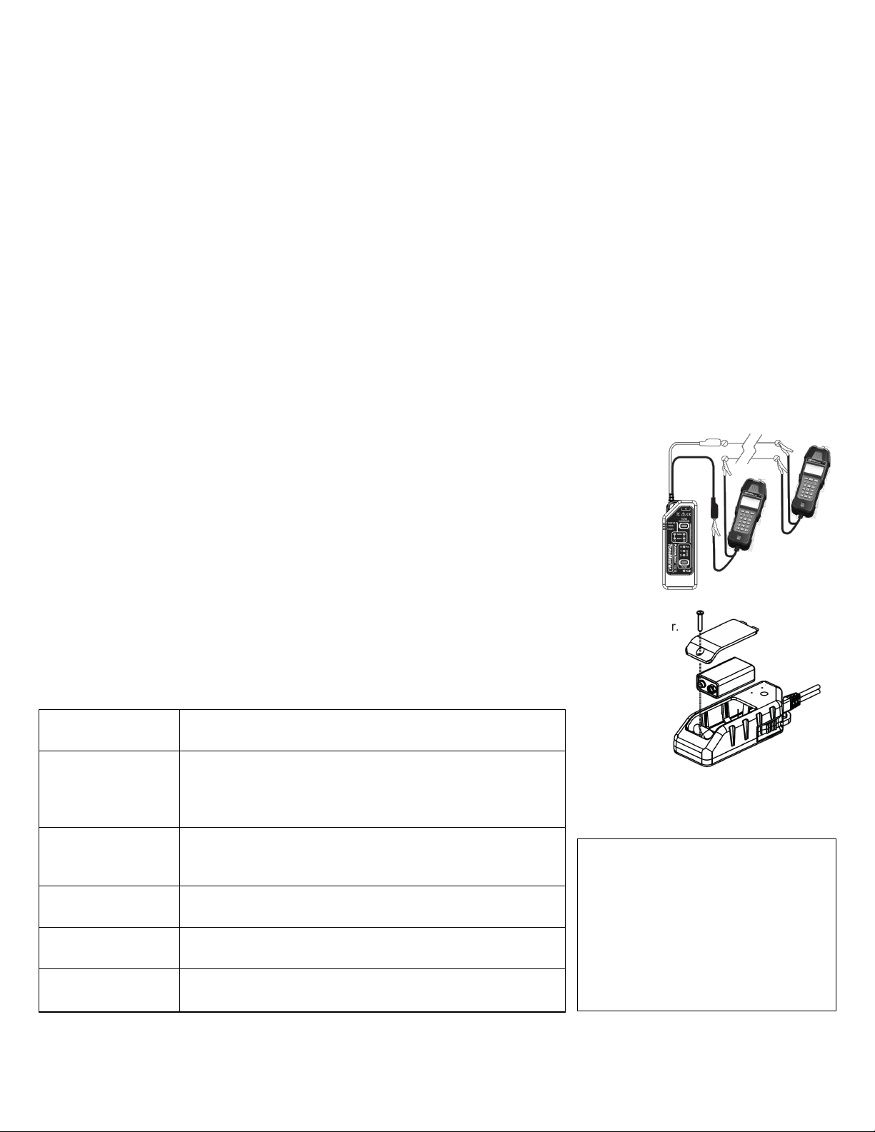
To supply TALK battery power to an unpowered line
This mode provides power to a dry line (not connected to a live circuit) allowing the testing of the line be-
tween two test sets.
1. Slide the mode switch to CONT with the TONE off.
2. Connect one lead from the tone generator to one lead of the phone set and connect the two remaining
free leads to the dead pair.
3. Connect a second phone set across the dead pair at the other end of the line.
4. Take both phone sets off hook (TALK mode) and communications is established. There would be no
dial tone but your voice or DTMF tones would be audible on the other phone.
5. When done, move slide switch to “STATUS”. The Tone Generator draws no power when the leads are
open, but the leads touching during storage could drain the battery.
BATTERY REPLACEMENT
1. Remove the screw on the rear of the tone generator with a #1 Phillips screwdriver and remove battery door.
2. Remove the old battery and disconnect it from the battery leads.
3. Snap the battery leads onto a new battery (9V, alkaline). Place the battery in the battery compartment.
4. Replace the battery door and the battery door screw. Do not overtighten.
SPECIFICATIONS
Specifications are subject to change without notice.
www.platinumtools.com
Tone Frequencies (±1%)
– Dual 1,165Hz and 874Hz
– Two single tones 1165Hz and 874Hz
Tone Power
Typical (into 600Ω, new battery to 5.0 V)
- LO 3.6dBm, HI 9.3dBm
High Power Mode
- LO 12.3dBm, HI 18.4dBm
Voltage Protection
Status - DC 60 V; continuous, AC 300 V peak, 2 secs
Continuity (into 600Ω) - DC 52 V
Tone Mode - 250 DC or peak AC volts
Electrical Battery Life
Time is for the full capacity of the battery used continuously (one 9 V alkaline,
540 mA-hr, not included): 120 hrs, typical
Environmental
Operating Temperature: 0 to 50C (32 to 122F)
Storage Temperature: -50 to 75C (-58F to 167F)
Physical
Dimensions 11.4 cm (4.5 in) x 4.4 cm (1.75 in) x 3.3 cm (1.3 in)
Weight (with battery) 42 gm (5.0 oz)
Warranty
Platinum Tools warrants this product to be free from
defects in material and workmanship for 12 months
for test equipment and 3 months for cables and accessories from the date of purchase. Liability is limited to the repair and or replacement of the product.
Warranty excludes batteries and cabling included
with the product. NO IMPLIED WARRANTIES OF
MERCHANTABILITY OR FITNESS FOR A PARTICULAR PURPOSE. Platinum Tools is not liable for
consequential damages.
IS TG210 ToneMaster GJ Rev B 10/17 California, USA Tel: 800.749.5783
 Loading...