

Platinum Tools LANSeeker TP500 User Manual
LIMITED WARRANTY
Platinum Tools Inc. guarantees to the end-user
purchaser that its products, and each of the parts
thereof, will be free of all defects in material and/or
workmanship. This warranty extends for a period of
12 months from the date of manufacture or proof-ofpurchase.
The obligations of Platinum Tools Inc. under this
warranty is limited to the repair or replacement (at
our option) during the warranty period of any part that
proves to be defective in material or workmanship
under normal use, installation and service, provided
the product is returned to Platinum Tools Inc. freight
prepaid.
Products returned to us must be accompanied by a
copy of the purchase receipt. In the absence of such a
receipt, the warranty period will cease 12 months from
the date of manufacture.
This warranty does not extend to acessories (such as
batteries, patch cords and pounches) or products which
have been subjected to neglect, accidental or improper
use, or to units which have been altered, repaired, or
inspected by other than Platinum Tools Inc. authorized
personnel. In no event will Platinum Tools Inc. be liable
for any incidental or consequential damages.
WARRANTY SERVICE
All units returned for warranty repair will be repaired or
replaced free of charge, at the discretion of Platinum
Tools Inc., and will be shipped freight prepaid. In the
event that a sales receipt or other dated proof-ofpurchase documentation is not available, a period of
not more than 12 months from date of manufacture
shall apply.
SERVICE
The LANSeeker™ is designed and manufactured
to provide trouble-free service. However, if for some
reason your tester should require repair, please follow
these instructions.
SHIPPING
1. Before returning any product to Platinum Tools
Inc., you must rst request a Return Goods
Authorization Number by contacting our Customer
Services Dept. at 805-384-2777. No shipments
will be accepted without this number, which must
be clearly marked on the shipping label.
2. Ship the tester with a copy of the sales receipt, if
available.
3. Attach a description of the operational problem.
4. Include a contact name, phone number and
e-mail address.
5. Pack securely to prevent damage during shipping.
6. Ship prepaid to: Platinum Tools Inc.
2450 Turquoise Circle
Newbury Park, CA 91320
99 Washington Street
Melrose, MA 02176
Phone 781-665-1400
Toll Free 1-800-517-8431
Visit us at www.TestEquipmentDepot.com
WARNINGS
Do not attach to energized cables. The LANSeeker™
may be damaged.
Caution!
Improperly crimped or un-crimped plugs can damage
the jacks on the LANSeeker™. Inspect plugs for
proper termination and crimping before inserting into
the tester. A sacrificial adapter, the RJ45 Port Saver,
is available from Platinum Tools (part number T124C)
to protect the jack on the tester. Contacts should
always be recessed into the plastic grooves of the plug.
BATTERY REPLACEMENT
When the battery low light is on while generating tone
or testing cables, the battery should be replaced as
soon as practical. The cable testing results will become
unreliable when the battery reaches about 4.5 volts.
To replace battery:
1) Remove rubber battery cap by peeling back a corner
until it pops off.
2) Pull battery out of cavity and remove battery snap.
3) Connect a new Alkaline 9 volt battery to battery
snaps.
4) Slide battery into cavity and snap cap in place.
We Make Connections EZ!
©2016 Platinum Tools, Inc. All rights reserved. LAN Seeker TP500 3/16
FEATURES
• Tests for shorts, opens, miswires, reversals
and split pairs
• Auto-on and auto-off when testing cables, just
plug both ends into tester!
• Automatically tests for shorts with one end
plugged into the tester
• Cable test results displayed on main unit
and remote unit, in less than 2 seconds after
plugging in the cable
• Snap-together case for easy storage and
convenient patch cable testing
• Tone generator mode for use with tone tracers,
auto-off
• Debug mode with from/to and failures for each
pair
• Battery low indicator
TP500 User Manual
INTRODUCTION
The LANSeeker™ cable tester is a unique blend of a
popular type of low
microprocessor controller. The most popular aspects of
this type of tester are an indication at both ends that the
cable has been tested, no buttons to push to perform
a test and a case that snaps together for storage.
The microprocessor brings the additional features of
automatic power management, split pair error detection,
direct indication of the type and location of faults and tone
generation. The patented split pair detection technique
allows the LANSeeker™ to have these advanced features
at a reasonable price.
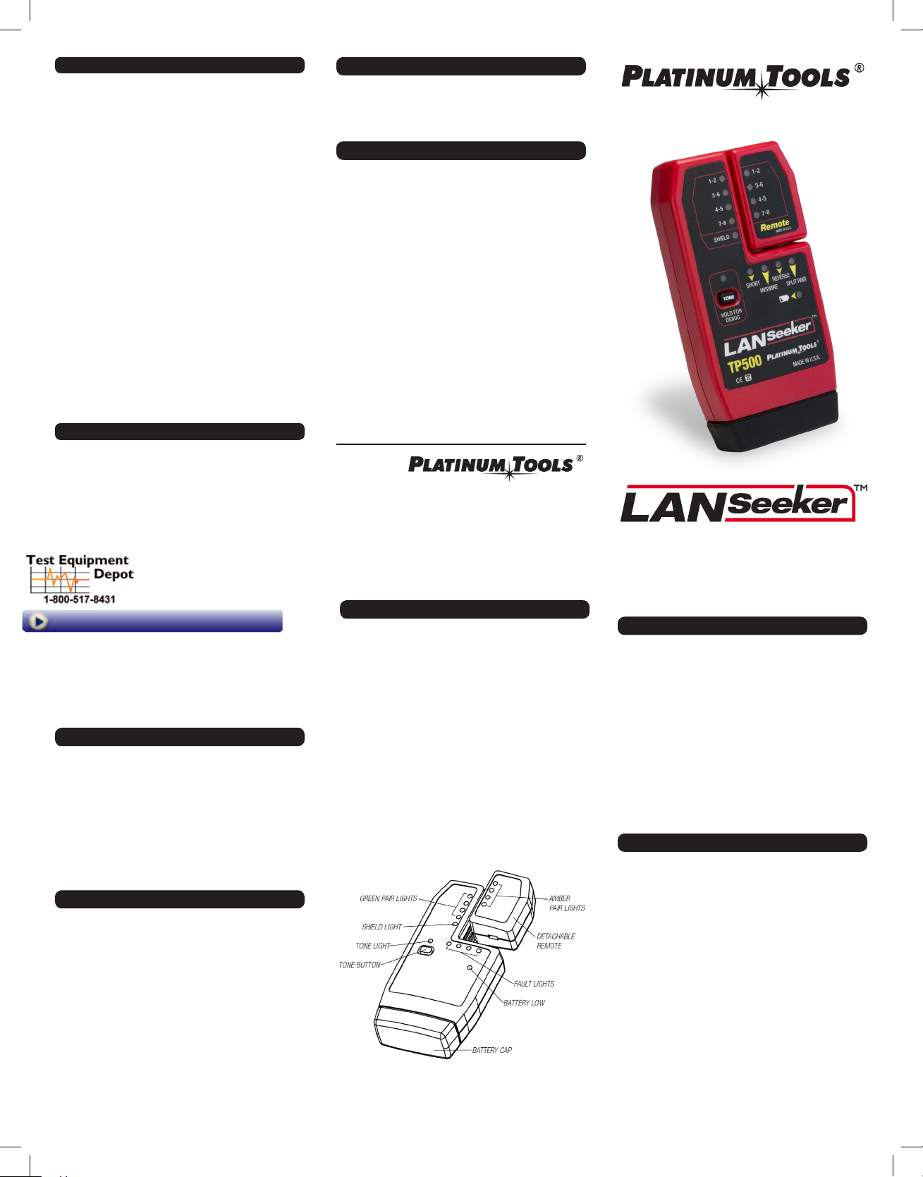
DESCRIPTION
The main unit has four green pair lights, a green shield
light, four red fault lights, a red battery low light and a
green tone light. The remote unit has four amber pair
lights. When a connection from the main unit to the
remote is sensed, testing begins automatically.
On the main unit, the lights for each pair will either
be ON, OFF or FLASHING. An ON light indicates a good
pair, an OFF light indicates an open pair and a
FLASHING light indicates a bad pair. If a pair is bad,
one or more of the fault lights will be flashing to
indicate the type or types of faults.
On the remote unit, the pair lights are either ON or
OFF. An ON light indicates a good pair, and an OFF
light indicates an open or bad pair. Holding down the
tone button until all lights momentarily turn on starts
the debug mode. The pairs are stepped through one at
a time to display connection and fault information on a
pair-by-pair basis.
A second press of the tone button turns off debug
-end tester interface with an advanced
SPECIFICATIONS
Electrical
Battery Life, typical alkaline times are for the full
capacity of the battery used continuously in one of the
following modes:
Standby: 2.5 years
Cable Testing: 20 hours
Tone Mode: 170 hours
Cable Types: Shielded or unshielded, Cat7, Cat6a, Cat6,
Cat 5e, Cat 5, Cat 4 or Cat 3
Minimum cable length for testing for split pairs: 1 meter
(3 feet)
Maximum cable length for testing: 305 meters (1000
feet)
Environmental
Temperature
Operating: 0 to 50°C (32 to 122°F)
Storage: -20 to 70°C ( -4 to 158°F)
Humidity: 10% to 90%, non-condensing
Physical
Length: 14.5 cm (5.70 in)
Width: 7.2 cm (2.85 in)
Height: 3.0 cm (1.20 in)
Weight (with battery): 162 gm (5.7 oz)
Specications are subject to change without prior
notication
INSTRUCTIONS FOR USE
LANSeeker™ powers off automatically after 5 minutes
of continuously testing a cable. Disconnecting the cable
restores normal function. Be sure to install a battery if
using for the rst time—see battery installation.
shielding effect of twisted pairs, the strongest
signal is obtained by connecting only one wire in
a cable to the tone source.
3. To turn tone off, press the TONE button a second
time. The tone will turn off automatically after 3
hours.
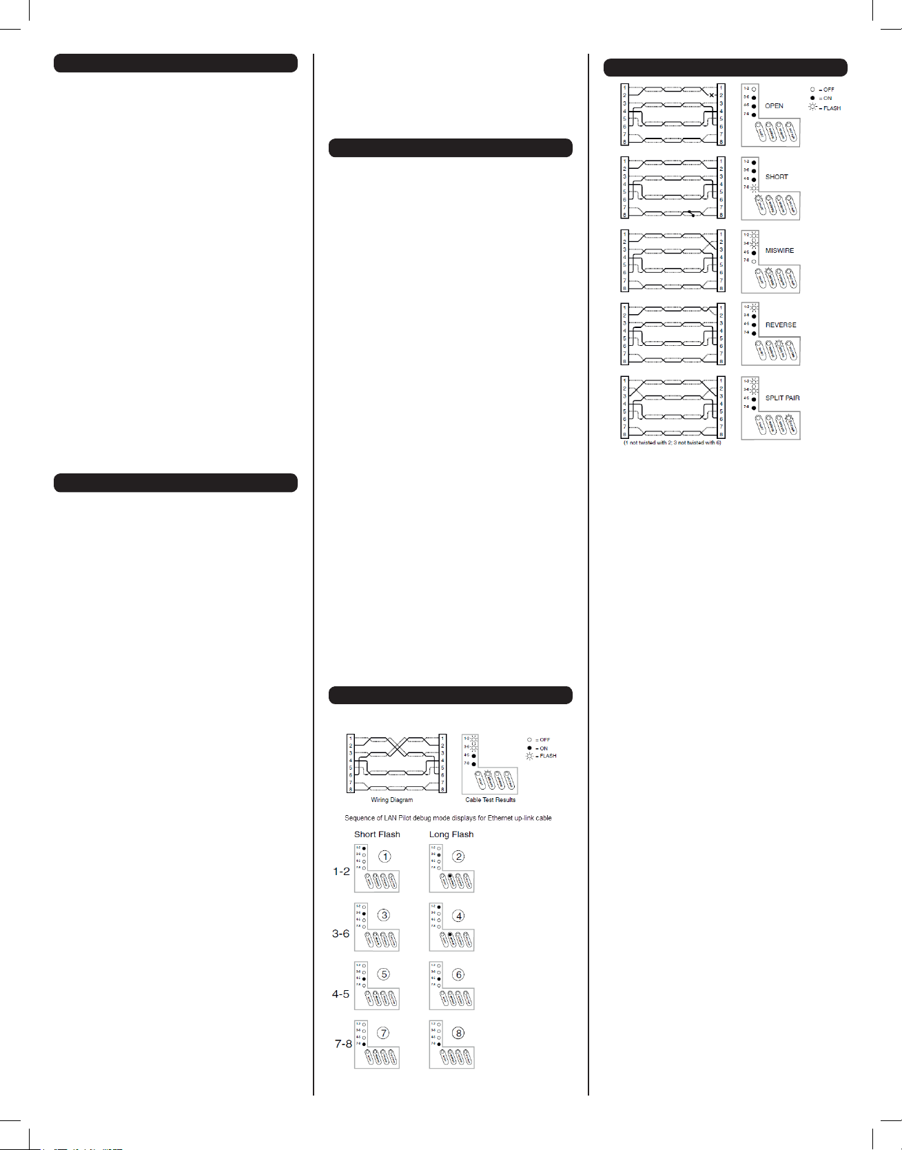
INTERPRETING RESULTS
The four fault lights are discussed below in order of
severity. The severity has to do with the ability of the
type of error to mask lower severity errors. For example,
if there is a short in the cable, miswires, reversals and
split pairs cannot be detected for the pairs involved in the
short fault. Multiple faults on multiple pairs can be better
understood by using the debug mode to examine the
errors one pair at a time.
Short – The pair has a low resistance connection from
one wire of the pair to the other wire of the pair or to any
other wire in the cable or the shield. A single ashing
pair light and the short light indicate a short within the
pair. Multiple ashing pair lights and only the short light
indicate shorts between the pairs involved.
Miswire – A wire or both wires of a pair are not connecte
to the correct pins at the other end of the cable. Debugs
“from–to” format is very helpful in visualizing what the
specic miswire is.
Reverse – A reverse is a special case of a miswire in
which the pair is wired to the correct pair of pins or to
another designated pair of pins, but the two leads are
reversed.
Split Pair – A split pair is an error in the twisting of the
wires together within the cable. The cables generally are
made up of eight wires twisted together in 4 pairs.
These 4 pairs are designated as pairs by the wiring
standards and are intended to carry a signal and it’s
return. 1 & 2, 3 & 6, 4 & 5 and 7 & 8 are the pairs
designated by T568A/B. A cable can be wired with
correct continuity, but not with correct pairing. This most
EXAMPLES OF WIRING ERRORS
Main Unit Results – The main unit indicates the
beginning of a test by ashing the pair lights in sequence
top to bottom. The cable is then tested and the results
displayed as follows:
Pair light off – Pair is open. Depending on the wiring
standard, this may be correct.
Pair light on – Pair is wired correctly.
To Test a Patch Cable
1. Plug one end of patch cable into main unit.
2. Plug other end of cable into remote unit.
3. The tester will power on immediately, indicating
a test in progress by quickly winking the pair
lights on both the main and remote; it will then
be followed by a combination of pair lights on —
this shows the test results.
4. Disconnect patch cable after test. The test
repeats automatically every 2.3 seconds if the
cable has only open and passing pairs and
repeats every 4 seconds if there are failures.
To Test Installed Cable (Ofce jack to patch panel)
1. Remove remote unit from main unit by sliding
remote towards top of the main unit.
2. Attach one end of a one foot jumper cable to
remote and other end to wall jack.
3. Attach one end of the a second one-foot jumper
to main unit and the other end to the patch panel
jack.
4. The tester will power on immediately, indicating
a test in progress by quickly winking the pair
lights on both the main and remote; it will be
immediately followed by a combination of pair
lights on — this shows the test results.
5. Disconnect after test. The test repeats
automatically every 2.3 seconds if the cable has
only open and passing pairs and repeats every 4
seconds if there are failures.
Application Hints: The jumper cables must be short
compared to the cable run for accurate split pair
indication, no more than 10% of the total run length.
To Place Tone on a Cable
1. Press and release the TONE button. The light
immediately above the button will start ashing.
2. Connect cable to be traced to main unit. For
best signal, do not connect remote. Due to the
Test Equipment Depot - 800.517.8431 - 99 Washington Street Melrose, MA 02176
often happens when the cable is terminated consistently
at both ends, but in the wrong order.
A dynamic or AC test is required to detect this type of
error. If the only error is a split pair error, the cable has
correct continuity. If cross talk is not a concern, as in at
satin cable, the cable is good if the only error is the split
pair error.
ETHERNET UP-LINK CABLE EXAMPLE
1-2 and 3-6 swapped
Pair connected from
1-2 to 3-6 (miswire)
Pair connected from
3-6 to 1-2 (miswire)
Pair connected from
4-5 to 4-5 (good)
Pair connected from
7-8 to 7-8 (good)
TestEquipmentDepot.com
Pair light is ashing – One or more errors were
detected for this pair, as indicated by ashing error
lights.
If there are no ashing lights, the results are displayed
for 2 seconds.
If there was an error, the results are displayed for twice
as long.
If the lights for the pairs expected are on, the cable is
good.
Remote Unit Results – The remote unit indicates the
beginning of a test by ashing the pair lights quickly, the
order or number of lights ashed depends on the cable
being tested.
Debug Mode – (See “Ethernet Up-Link Cable Example”)
The debug mode is provided to allow diagnosis of faults,
especially when there are multiple errors on multiple pairs.
To enter the debug mode, press and hold the tone button
until all lights on the main unit light (lamp test). Once the
lamp test is complete, debug displays the results of the
last cable test. This is from internal memory, so the cable
is not required to be connected when running debug.
The debug display begins with a short ash on the 1-2
pair to indicate that what follows is the result for the 1-2
pair test (or the “from”). If the pair was not open, a second
longer ash on one or more pair lights designates what
pair 1-2 is connected “to” at the remote end, or pairs
involved in a fault condition along with the fault lights. The
3-6, 4-5 and 7-8 pair lights each in turn begin with a short
ash followed by the results for that pair.
The individual pair results continue to be displayed until
the tone button is pressed again or two complete cycles of
all pairs is completed.
The remote unit does not display anything when in debug
mode.
 Loading...