

Page 1
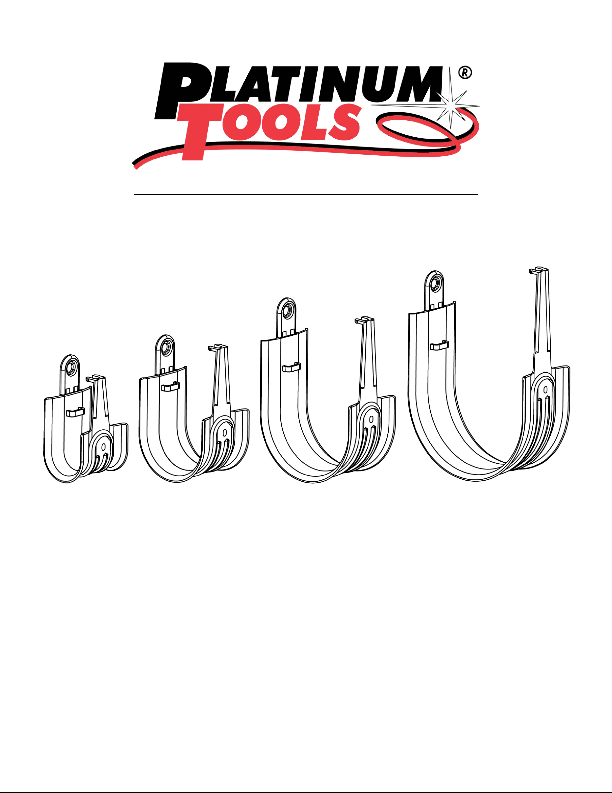
HPH Series J-Hook Installation Instructions
1
Page 2
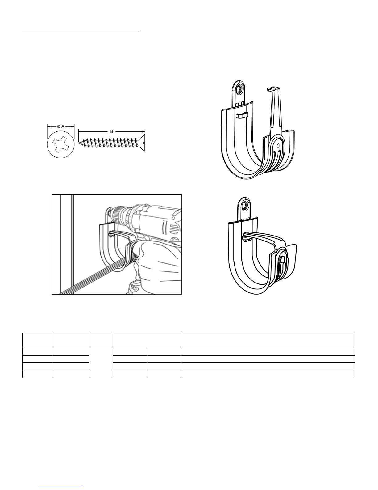
Mounting to a vertical surface: HPH16, HPH32, HPH48 and HPH64
Part
Hook
Fig.
UL Load Rating
Description
HPH16
1"
20
88.96
1” Standard HPH J-Hook, size 16
HPH32
2”
17
75.62
2” Standard HPH J-Hook, size 32
HPH48
3”
20
88.96
3” Standard HPH J-Hook, size 48
HPH64
4”
17
75.62
4” Standard HPH J-Hook, size 64
Use a nail*, bolt* or screw* with a minimum head diameter of 0.329” (Fig.1-A) and an
appropriate length for the substrate (Fig.1-B) to fasten the HPH J-Hook (Fig.2) to the vertical
surface (Fig.3). Insert the cables and close the latch as shown in Fig.3. The latch must be in the
closed position as shown in Fig.4 to secure the cables and complete the installation.
Fig.1 Fig.2
Fig.3 Fig.4
No.
Size
No.
2 & 4
LBS. | N
2
Page 3
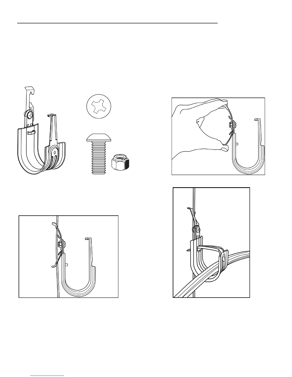
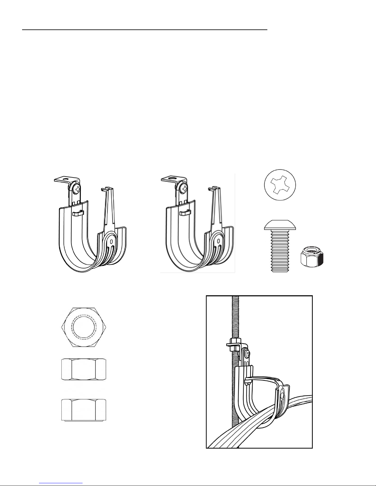
Mounting to a rod or ceiling wire with a Multi-Function Clip-Batwing: HPH16W,
HPH32W, HPH48W and HPH64W
HPHXXW J-Hooks (Fig.1) are pre-assembled to Multi-Function Clip-Batwings at the factory using
a fastener such as a rivet or a zinc plated ¼-20 x 3/8” pan head Phillips machine bolt and a
grade A ¼-20 hex Nylon locknut (Fig.2). A plain HPH J-Hook may be assembled to a UL listed
batwing clip in the field with the use of a similar fastener. Depress the batwing between your
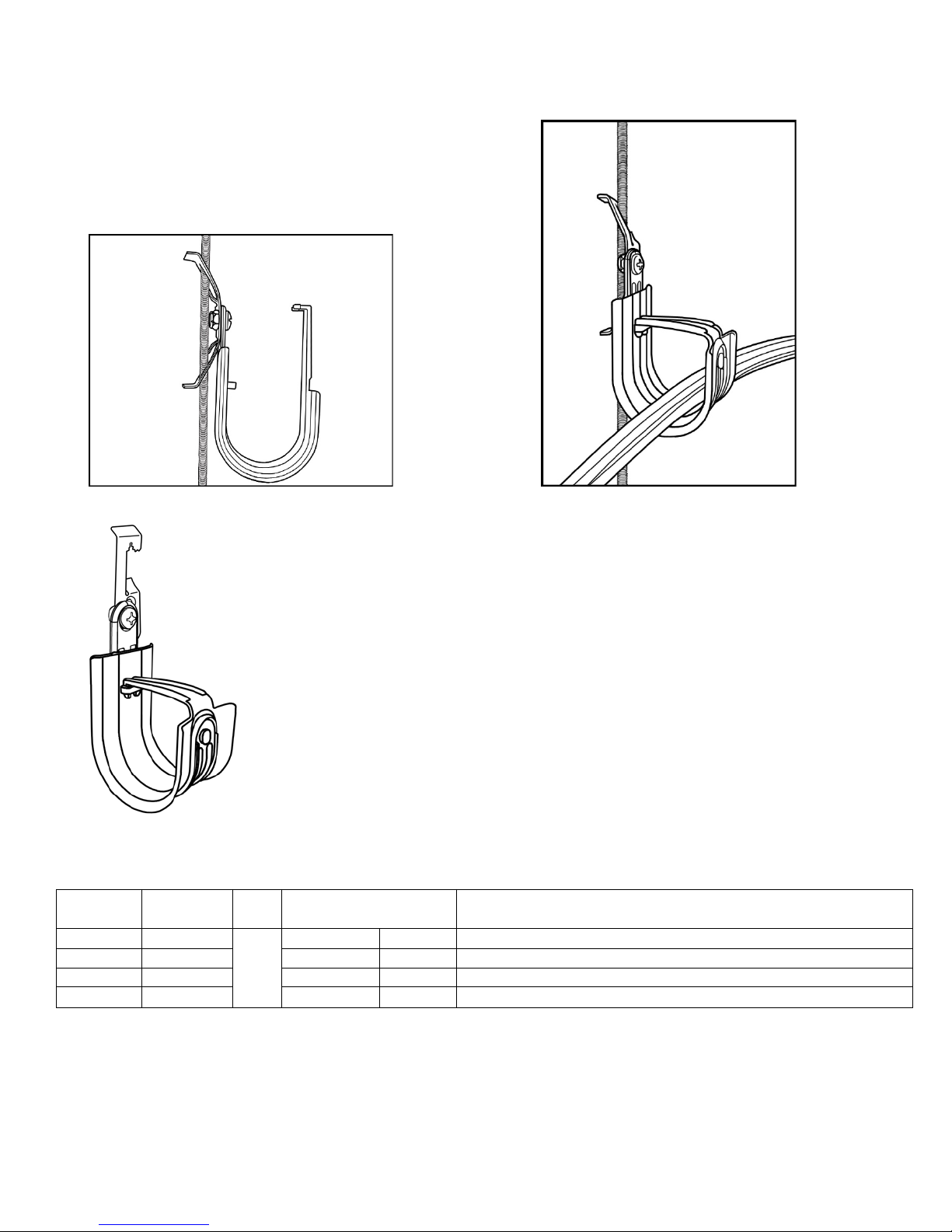
fingers (Fig. 3). Attach the HPHXXW to 12 gauge ceiling wire or 1/4" threaded rod (Fig.4 and
Fig.6).
position as shown in Fig.8 to secure the cables and complete the installation.
Insert the cables and close the latch (Fig.5 and Fig.7). The latch must be in the closed
Fig. 1 Fig. 2 Fig. 3
Fig. 4 Fig. 5
3
Page 4
Part No.
Hook
Fig.
UL Load Rating
Description
HPH16W
1"
20
88.96
1” Batwing HPH J-Hook, size 16
HPH32W
2”
20
88.96
2” Batwing HPH J-Hook, size 32
HPH48W
3”
20
88.96
3” Batwing HPH J-Hook, size 48
HPH64W
4”
20
88.96
4” Batwing HPH J-Hook, size 64
Fig. 6 Fig. 7
Fig. 8
Size
No.
1
&
8
LBS. | N
4
Page 5
Mounting to a rod or a horizontal surface with an Angle Clip 90°: HPH16AC, HPH16AC6
HPH32AC, HPH32AC6, HPH48AC, HPH48AC6, HPH64AC & HPH64AC6
HPHXXAC and HPHXXAC6 J-Hooks (Fig.1 and Fig.2) are pre-assembled to Angle Clips 90° at the
factory using a fastener such as a rivet or a zinc plated ¼-20 x 3/8” pan head Phillips machine
bolt and a grade A ¼-20 hex Nylon locknut (Fig.3). A plain HPH J-Hook may be assembled to a
Platinum Tools Angle Clip 90° in the field using a similar fastener. Fasten the HPHXXAC or
HPHXXAC6 to 1/4" or 3/8” threaded rod using two standard hex nuts (Fig.4). Thread a single nut
up to the desired location of the threaded rod. Guide the HPHXXAC or HPHXXAC6 onto the
threaded rod. Thread a second nut onto the threaded rod and tighten to the first nut, thereby
sandwiching the Angle Clip 90° between the two nuts (Fig.5). An HPHXXAC or an HPHXXAC6
may be fastened directly to the underside of a horizontal surface using an appropriate fastener*
(Fig.6). Use a fastener with an appropriate head diameter (Fig.7-A) and an appropriate length
for the substrate (Fig.7-B). Place the cables in the hook and close the latch as shown in Fig.5
and Fig.6. The latch must be in the closed position as shown in Fig.8 and Fig.9 to secure the
cables and complete the installation.
Fig.1 Fig.2 Fig. 3
Fig. 4 Fig. 5
5
Page 6

Part No.
Hook
Fig.
UL Load
Angle Clip
Description
HPH16AC
1"
1
20
88.96
1/4"
1” 90° Angle HPH J-Hook, size 16
HPH16AC6
1”
2
20
88.96
3/8”
1” 90° Angle/6 HPH J-Hook, size 16
HPH32AC
2”
1
20
88.96
1/4"
2” 90° Angle HPH J-Hook, size 32
HPH32AC6
2”
2
20
88.96
3/8”
2” 90° Angle/6 HPH J-Hook, size 32
HPH48AC
3”
1
20
88.96
1/4"
3” 90° Angle HPH J-Hook, size 48
HPH48AC6
3”
2
20
88.96
3/8”
3” 90° Angle/6 HPH J-Hook, size 48
HPH64AC
4”
1
20
88.96
1/4"
4” 90° Angle HPH J-Hook, size 64
HPH64AC6
4”
2
20
88.96
3/8”
4” 90° Angle/6 HPH J-Hook, size 64
Fig. 6 Fig. 7
Fig. 8 Fig. 9
Size
No.
LBS. | N
Rating
Hole Size
6
Page 7

Mounting to a horizontal surface with an Angle Clip 90° w/Powder Actuated Nail
Part No.
Hook
Fig.
Load Rating
Description
HPH16ACPA
1"
20
88.96
1” 90° Angle w/PAN HPH J-Hook, size 16
HPH32ACPA
2”
20
88.96
2” 90° Angle w/PAN HPH J-Hook, size 32
HPH48ACPA
3”
20
88.96
3” 90° Angle w/PAN HPH J-Hook, size 48
HPH64ACPA
4”
20
88.96
4” 90° Angle w/PAN HPH J-Hook, size 64
(PAN): HPH16ACPA, HPH32ACPA, HPH48ACPA and HPH64ACPA
Use a powder actuated tool* to install the 1-5/16” pin into an appropriate material such as
concrete as shown in Fig. 3 & 4.
Fig.1 Fig.2
Fig.3 Fig.4
Size
No.
1
&
2
LBS. | N
7
Page 8

Mounting to a beam with an HOK24 or HOK58 Hammer-On Beam Clamp: HPH16HOK24,
Part No.
Hook
Fig.
UL Load
LBS. | N
Designed
Description
HPH16HOK24
1"
1 & 2
20
88.96
1/8” - 1/4"
1” Hammer-On HPH J-Hook, 1/8”-1/4” flange, size 16
HPH16HOK58
1”
3 & 4
20
88.96
5/16 - 1/2”
1” Hammer-On HPH J-Hook, 5/16”-1/2” flange, size 16
HPH32HOK24
2”
1 & 2
17
75.62
1/8” - 1/4"
2” Hammer-On HPH J-Hook, 1/8”-1/4” flange, size 32
HPH32HOK58
2”
3 & 4
17
75.62
5/16 - 1/2”
2” Hammer-On HPH J-Hook, 5/16”-1/2” flange, size 32
HPH48HOK24
3”
1 & 2
20
88.96
1/8” - 1/4"
3” Hammer-On HPH J-Hook, 1/8”-1/4” flange, size 48
HPH48HOK58
3”
3 & 4
20
88.96
5/16 - 1/2”
3” Hammer-On HPH J-Hook, 5/16”-1/2” flange, size 48
HPH64HOK24
4”
1 & 2
17
75.62
1/8” - 1/4"
4” Hammer-On HPH J-Hook, 1/8”-1/4” flange, size 64
HPH64HOK58
4”
3 & 4
17
75.62
5/16 - 1/2”
4” Hammer-On HPH J-Hook, 5/16”-1/2” flange, size 64
HPH16HOK58, HPH32HOK24, HPH32HOK58, HPH48HOK24, HPH48HOK58,
HPH64HOK24 and HPH64HOK58
Secure a Hammer-On Beam Clamp to a flange using a hammer as shown in Fig. 5 & Fig. 6
below.
Note: The HOK-24 is designed for flanges from 1/8” to 1/4" thick; the HOK-58 is designed for
flanges from 5/16” to 1/2" thick.
Fig.1 Fig.2 Fig.3 Fig.4
Size
No.
Rating
for flanges
Fig.5 Fig.6
8
Page 9

Part No.
Hook
Fig.
UL Load
Designed for
Description
HPH16ACFM24
1"
1 & 2
20
88.96
1/8” - 1/4"
1” Hammer-On HPH J-Hook, Swivels 360°, 1/8”-1/4”
Flange, size 16
HPH16ACFM58
1”
3 & 4
20
88.96
5/16 - 1/2”
1” Hammer-On HPH J-Hook, Swive l s 3 60° , 5/16” – 1/2"
Flange, size 16
HPH32ACFM24
2”
1 & 2
20
88.96
1/8” - 1/4"
2” Hammer-On HPH J-Hook, Swivels 360°, 1/8”-1/4”
Flange, size 32
HPH32ACFM58
2”
3 & 4
20
88.96
5/16 - 1/2”
2” Hammer-On HPH J-Hook, Swive l s 3 60° , 5/16” – 1/2"
Flange, size 32
HPH48ACFM24
3”
1 & 2
20
88.96
1/8” - 1/4"
3” Hammer-On HPH J-Hook, Swivels 360°, 1/8”-1/4”
Flange, size 48
HPH48ACFM58
3”
3 & 4
20
88.96
5/16 - 1/2”
3” Hammer-On HPH J-Hook, Swive l s 3 60° , 5/16” – 1/2"
Flange, size 48
HPH64ACFM24
4”
1 & 2
20
88.96
1/8” - 1/4"
4” Hammer-On HPH J-Hook, Swivels 360°, 1/8”-1/4”
Flange, size 64
HPH64ACFM58
4”
3 & 4
20
88.96
5/16 - 1/2”
4” Hammer-On HPH J-Hook, Swive l s 3 60° , 5/16” – 1/2"
Flange, size 64
Mounting to a beam with an FM24 or FM58 Hammer-On Beam Clamp: HPH16ACFM24,
HPH16ACFM58, HPH32ACFM24, HPH32ACFM58, HPH48ACFM24, HPH48ACFM58,
HPH64ACFM24
and HPH64ACFM58
Secure a knock-on beam clamp to a flange using a hammer as shown in Fig. 5 & Fig. 6 below.
Note: The ACFM24 is designed for flanges from 1/8" to 1/4" thick. The ACFM58 is designed for
flanges from 5/16" to 1/2" thick. Both the ACFM24 & ACFM58 can be rotated 360°.
Fig.1 Fig.2 Fig.3 Fig.4
Size
No.
Rating
LBS. | N
flanges
Fig.5 Fig.6
9
Page 10

Mounting to a beam with a BC Beam Clamp: HPH16BC, HPH16ACBC, HPH32BC,
Part No.
Hook
Fig.
UL Load
Designed
Description
HPH16BC
1"
1 & 2
20
88.96
1” Beam Clamp HPH J-Hook, Size 16
HPH16ACBC
1”
3 & 4
20
88.96
1” Swivel 360° Beam Clamp HPH J-Hook, size 16
HPH32BC
2”
1 & 2
17
75.62
2” Beam Clamp HPH J-Hook, Size 32
HPH32ACBC
2”
3 & 4
20
88.96
2” Swivel 360° Beam Clamp HPH J-Hook, size 32
HPH48BC
3”
1 & 2
20
88.96
3” Beam Clamp HPH J-Hook, Size 48
HPH48ACBC
3”
3 & 4
20
88.96
3” Swivel 360° Beam Clamp HPH J-Hook, size 48
HPH64BC
4”
1 & 2
17
75.62
4” Beam Clamp HPH J-Hook, Size 64
HPH64ACBC
4”
3 & 4
20
88.96
4” Swivel 360° Beam Clamp HPH J-Hook, size 64
HPH32ACBC, HPH48BC, HPH48ACBC, HPH64BC and HPH64ACBC
Secure a screw-on beam clamp to a flange using a 3/8” socket driver or wrench as shown in
Fig.5, 6, 7, & 8 below. Tighten the bolt to 20 in-lb.
Note: The BC & ACBC’s are designed for flanges up to 1/2" thick. The ACBC can be rotated 360°.
Fig.1 Fig.2 Fig.3 Fig.4
Size
No.
Rating
LBS. | N
for
flanges
1/8” - 1/2"
Fig.5 Fig.6
10
Page 11

Fig.7 Fig.8
Mounting to a beam with an SSBC Spring Steel Beam Clamp: HPH16SSBC,
HPH16ACSSBC, HPH32SSBC, HPH32ACSSBC, HPH48SSBC, HPH48ACSSBC, HPH64SSBC
and HPH64ACSSBC
Secure a screw-on beam clamp to a flange using a 3/8” socket driver, wrench or Phillips head
screw driver as shown in Fig. 5, 6, & 8 below. Tighten the bolt to 20 in-lb.
Note: The SSBC & ACSSBC’s are designed for flanges up to 1/2" thick. The ACSSBC can b e
rotated 360°.
Fig.1 Fig.2 Fig.3 Fig.4
11
Page 12

Part No.
Hoo
Fig.
UL Load
Designed
Description
HPH16SSBC
1"
1 & 2
20
88.96
1” Spring Steel Beam Clamp H P H J-Hook, size 16
1” Swivel 360° Spring Steel B ea m Clamp HPH
J-Hook, size 16
HPH32SSBC
2”
1 & 2
17
75.62
2” Spring Steel Beam Clamp HPH J-Hook, size 32
2” Swivel 360° Spring Steel B ea m Clamp HPH
J-Hook, size 32
HPH48SSBC
3”
1 & 2
20
88.96
3” Spring Steel Beam Clamp H P H J-Hook, size 48
3” Swivel 360° Spring Steel B ea m Clamp HPH
J-Hook, size 48
HPH64SSBC
4”
1 & 2
17
75.62
4” Spring Steel Beam Clamp H P H J-Hook, size 64
4” Swivel 360° Spring Steel B ea m Clamp HPH
J-Hook, size 64
Fig.5 Fig.6
Fig.7 Fig.8
k
No.
Size
HPH16ACSSBC 1” 3 & 4 20 88.96
HPH32ACSSBC 2” 3 & 4 20 88.96
HPH48ACSSBC 3” 3 & 4 20 88.96
HPH64ACSSBC 4” 3 & 4 20 88.96
Rating
LBS. | N
for
flanges
1/8” - 1/2"
12
Page 13

Mounting to a joist with an Angled Overhang (AO) or Vertical Overhang (VO) spring
steel clip: HPH16AO, HPH16VO, HPH32AO, HPH32VO, HPH48AO, HPH48VO, HPH64AO
and HPH64VO
Secure an AO spring steel “Z” purlin clip or a VO14 “C” purlin clip to a joist using a hammer as
shown in Fig. 5, 6, 7, & 8 below.
Note: The AO14 is designed for flanges 1/8” - 1/4" thick.
Fig.1 Fig.2 Fig.3 Fig.4
Fig.5 Fig.6
13
Page 14

Part No.
Hook
Fig.
UL Load
Designed
Description
HPH16AO
1"
1 & 2
20
88.96
1” Angled Overhang HPH J-Hook, size 16
HPH16VO
1”
3 & 4
20
88.96
1” Vertical Overhang HPH J-Hook, size 16
HPH32AO
2”
1 & 2
17
75.62
2” Angled Overhang HPH J-Hook, size 32
HPH32VO
2”
3 & 4
17
75.62
2” Vertical Overhang H PH J-Hook, size 32
HPH48AO
3”
1 & 2
20
88.96
3” Angled Overhang HPH J-Hook, size 48
HPH48VO
3”
3 & 4
20
88.96
3” Vertical Overhang HPH J-Hook, size 48
HPH64AO
4”
1 & 2
17
75.62
4” Angled Overhang HPH J-Hook, size 64
HPH64VO
4”
3 & 4
17
75.62
4” Vertical Overhang H PH J-Hook, size 64
Fig.7 Fig.8
Size
No.
Rating
LBS. | N
for
flanges
1/8” - 1/4"
14
Page 15

Mounting to threaded rod with a female threaded eye coupling: HPH16EH, HPH32EH,
Part No.
Hook
Fig.
Load Rating
Description
HPH16EH
1"
20
88.96
1” End Hook ¼-20 HPH J-Hook, size 16
HPH32EH
2”
20
88.96
2” End Hook ¼-20 HPH J-Hook, size 32
HPH48EH
3”
20
88.96
3” End Hook ¼-20 HPH J-Hook, size 48
HPH64EH
4”
20
88.96
4” End Hook ¼-20 HPH J-Hook, size 64
HPH48EH and HPH64EH
Thread the eye coupling on to ¼-20 threaded rod as shown in Fig. 3, 4 & 5 below.
Fig.1 Fig.2
Fig.3 Fig.4 Fig.5
Size
No.
1
&
2
All HPH J-Hooks on pages 6 through 15 are special order. Call us for details and lead times.
* Consult the manufacturer’s instructions and load ratings before using on your application.
www.platinumtools.com
LBS. | N
15
 Loading...