


PA5000 SERIES
4G CELL PHONE ENTRY SYSTEM
USER MANUAL
Rev. C
Platinum Access Systems Inc.

PRODUCT LINE
PA5020 --- Cell Phone Entry System
PA5022 --- Cell Phone Entry System (Flush Mount)
SPECIFICATIONS AND FEATURES
1.
4G LTE Link
Support major US carriers (AT&T, T-Mobile, etc).
2.
Remote Operation From Smartphone App
This unit can be remotely operated from smartphones Apps. Support both iOS and Android smartphones.
3.
2000 Phone Number Capacity
4.
2 Sets of Key Entry Code
4 Digit mode for primary and secondary gate operation.
5.
USB Programming Capability
With the Platinum USB drive, the phone number and key code can be uploaded and downloaded to the unit.
6.
2000 History Log
7.
Remote Open Operation with Phone Keypad
During phone call, the gate open operation can be performed on remote phone unit.
8.
Temporary Key Code Assignment
A temporary key code and valid period can be set via smartphone App.
9.
Hold Open and Scheduled Hold Open Operation
A 5-digit code can be programmed to activate hold open operation on keypad.
Scheduled hold open operation is configured via smartphone App,
10.
Modify Key Code and Phone Number Remotely
Key code and phone number can be modified via smartphone App.
11.
Request to Exit Input
A NO (Normal Open) contact input for codeless open operation.
12.
Gate Status Check Inputs
2 inputs can be used to check gate status via smartphone App.
13.
Control Outputs
2 NO/NC 8A @ 30VDC relays. The strike durations are programmerable. 1 AUX output, 300 mA solid state..
14.
Real Time Clock
The date and time can be set and checked via smartphone App.
15.
Master/Slave Configuration
The unit can work as a master unit with multiple slave devices (Platinum keypad).
16.
Wide DC Power Supply Range and Battery Backup
9-28V / 2A DC Power Supply (Default AC/DC adaptor: 12V/2A). The internal rechargeable battery provides >5
hours power backup. The unit will alarm when the battery voltage is low.
2
INSTALLATION
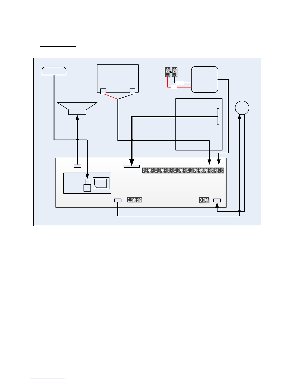
1. Internal Wiring
Fig.1 shows the factory internal wiring diagram.
Antenna
Battery
+ -
Speaker
9-28V DC IN
+
1
2
2
1
2
C
N
C
M
M
O
C
O
O
O
N
N
N
C
-
DC/DC
Black
Red
1
T
T
D
I
U
N
X
O
G
E
Module
Call Button
Keypad
1
2
N
N
I
I
- 9VDC +-BAT2+ -BAT1+
SIM
A B GND
Fig, 1 Internal Wiring
- SOL +
2. External Wiring
Fig.2 shows the external wiring diagram.
Note:
a. External DC power source is connected on +/- “9-28V DC IN” terminals. See Fig.1,
b. Primary operator limit switch wiring is for gate status monitoring purpose only. It is optional.
c. Slave keypads are within 2000ft range.
3
IN1
GND
IN2
Open Limit SW
NC
NO
NC
NO
Close Limit SW
COM
COM
Limit SW
Terminal
OPEN SW
GND
CLOSE SW
GND
OPERATOR
CONTROL BOARD
EXIT
Button
Secondary
Gate Lock
PA5000 CASE
AUX
Device
LO ACTIVE
LO ACTIVE
DC PS
SIM
A B GND
LO STRIKE
Primary
Gate Operator
Limit
SW
2
2
M
C
O
N
C
1
2
1
1
M
O
C
O
O
N
N
N
C
T
T
D
I
2
U
N
O
G
1
X
N
N
I
I
E
- 9VDC +-BAT2+ -BAT1+
- SOL +
SLAVE KEYPAD (ID 0)
1
2 3
4 5 6
7 8 9
* 0 #
PLATINUM
PA1030 (4 Digit Mode)
SLAVE KEYPAD (ID 99)
A
B
...
GND
PLATINUM
PA1030 (4 Digit Mode)
1
4 5 6
7 8 9
* 0 #
4
2 3
A
B
GND
Fig, 2 External Wiring

3. SIM Card Installation
With power off, plug an active regular size SIM card into the SIM card holder. See Fig.3 for SIM card orientation.
If only micro or nano SIM card is available, SIM card adapter is required, see Fig.3 for SIM card orientation and
card adapters.
Fig. 3 SIM Card Orientation and Adapters
Install the SIM card as shown in Fig. 4.
Fig. 4 SIM Card Installation
4. Indicators and Switches
See Fig.5. Front Panel
Note: Link LED will flash when the unit is registered to local GSM network. No phone call can be made
without Link LED flashing.
5

Fig. 5 Font Panel
OPERATIONS
1.
System Reset
Push “RESET” button to initialize the unit. Allow 20 sec for the unit to boot up.
2.
“*” Button Operation
During key entry, press “*” button to cancel the keys entered.
During phone call, press “*” button to hang up phone.
3.
Program Mode
Selected by Mode Switch at “PROG” position. Status LED is flashing in "Yellow”.
(1). Programming Status:
Beeping twice with green light: Program success
Beeping once with red light: Program fail
(2). Program Key Code:
Primary Code: xxxx + “#” Enter 4-digit key code followed by “#”.
Secondary Code: “2#” + xxxx + “#” Enter “2#” and 4-digit key code followed by “#”.
(3). Program Phone Number:
Phone ID (0-1999) + “CALL”+ area code + phone number + “#”
Ex: 0+”CALL”+9491234567#
12+”CALL”+6261234567#
123+”CALL”+7141234567#
1234+”CALL”+9091234567#
Note: Duplicate phone numbers under different phone ID are acceptable.
(4). Set Talk Duration: #60x x: 1-9, 1 to 9 min (default 5 min)
(5). Set Relay1 Strike Duration: #7xx xx: 2-digit 01-99, 1s to 99s
(6). Set Relay2 Strike Duration: #8xx xx: 2-digit 01-99, 1s to 99s
6

(7). Set Hold Open Code: #3xxxxx xxxxx: 5-digit 00000-99999
(8). Assign Authorized Smartphone App User Phone Numbers:
#131xxxxxxxxxx Program #1 phone umber
#132xxxxxxxxxx Program #2 phone umber
#133xxxxxxxxxx Program #3 phone umber
#134xxxxxxxxxx Program #4 phone umber
#135xxxxxxxxxx Program #5 phone umber
xxxxxxxxxx: 3 area code + 7 phone number
(9). Program from Platinum USB Drive: #411 Download phone book and key codes from Platinum USB
drive to the unit.
a. Using Platinum standalone software “PHONE BOOK MANAGER”, edit and export phone book and
key codes to Platinum USB drive.
b. Plug in the Platinum USB drive to the unit.
c. Enter “#411” to download the phone book and key codes to the unit.
d. Status LED will be flashing in green during downloading. Downloading completes with 2 beeps.
Notes:
a. Platinum USB drive is included in the product package. It must contain “Platinum ID.doc” or “Platinum
ID.txt” and “CONF_D.txt”. “CONF_D.txt” is generated by “PHONE BOOK MANAGER” software.
b. Before downloading, the existing phone book and key codes in the unit will be read out and saved to
“CONF_BAK.TXT” file on Platinum USB drive.
c. Download new phone book and key codes from “CONF_D.TXT” file on Platinum USB drive to the
unit.
d. After downloading, new phone book and key codes in the unit will be read back and saved to
“CONF_BK1.TXT” file on Platinum USB drive as for verification purpose.
4.
Normal Mode
Selected by Mode Switch at “NORM” position. Status LED is off.
(1). Operation Status:
Beeping twice with green light: Operation success
Beeping once with red light: Operation fail
(2). Key Entry:
Primary Code: xxxx + “#” Enter 4-digit key code followed by “#”.
Secondary Code: “2#” + xxxx + “#” Enter “2#” and 4-digit key code followed by “#”.
(3). Phone Entry: Enter phone ID (0-1999) + “CALL” to make phone call.
Ex: “CALL”, 1+”CALL”, 25+”CALL”, 133+”CALL”, 1567+”CALL”
On the phone call receiver side, pressing “9” will activate relay1 output. And pressing “5” will activate
relay2 output.
Note: If ID#0 phone number is programmed, pressing “CALL” button only will call ID#0 phone number
automatically.
(4). Hold Open / Release Hold Open: #3xxxxx xxxxx (5-digit 00000-99999) Hold open or release hold open
(hold open control applies to relay1 only).
(5). Upload Programmed Code: #000 Upload phone book and key codes from the unit to Platinum USB
7

drive.
a. Phone book and key codes in the unit will be read out and saved to “CONF_BAK.TXT” file on
Platinum USB drive.
b. Status LED will be flashing in green during uploading. Uploading completes with two beeps.
(7). Upload History Log: #001 Upload history log from the unit to Platinum USB drive.
a. The history log file will be read out and saved to “LOG.TXT” file on Platinum USB drive.
b. Status LED will be flashing in green during uploading. Uploading completes with two beeps.
5.
Erase Mode
Selected by Mode Switch at “ERAS” position. Status LED is flashing in "Red”.
(1). Erase Status:
Beeping twice with green light: Erase success
Beeping once with red light: Erase fail
(2). Erase Key Code:
Primary Code: xxxx + “#” Enter 4-digit key code followed by “#”.
Secondary Code: “2#” + xxxx + “#” Enter “2#” and 4-digit key code followed by “#”.
(3). Erase Phone ID: ID (0-1999) + “CALL”
Ex: 0+”CALL”, 12+”CALL”, 123+”CALL”, 1234+”CALL”
(4). Erase All Primary Key Codes: #911
(5). Erase All Phone Numbers: #913
(6). Erase Hold Open Code: #914
(7). Erase All Authorized User Phone Numbers: #915
(8). Erase All Secondary Key Codes: #916
(9). Erase Hold Open Schedule: #917
6.
Master/Slave Mode
The unit will work as a master when connecting to Platinum keypads (set as slave/4digit mode) with 3 wire
(“A/B/GND”) shield cable. The key code entered on slave keypad unit will be sent to master unit to process.
Open command will be delivered to slave units upon valid key codes.
Note: The keypads must be set to “SLAVE” and 4 digit mode to work with master unit.
7.
Smartphone App. Download and Install
iPhone
In APPLE store, search for “Platinum Remote Access” and install the App on iPhone, APPLE account with
APPLE ID may be required to download and install the App.
8
iPhone Icon
Android Phone Icon

Android Phone
(1). Download App from Google Play Store
Log on Google Play Store. Search “Platinum Remote Access” and install the App on smartphone. Google
account may be required to download and install the App from Google Play Store.
(2). Download App from Platinum URL
a. On Android phone, enable “Unknown source” under Settings Applications or Settings Security.
b. Browse to “Downloads” tab at www.platinumasi.com and download “Smart Phone Application” to
the phone.
c. Navigate to the download folder on the phone, Applications Files Download, and tap on the
“Android Platinum Remote Access Vx.x.x.APK” to install the application.
d. When the installation completes, add the icon as shown above from “Applications” to Home Screen.
8.
Smartphone App. Operations
Launch “Platinum Remote Access” App. on smartphone.
(1). Unit Configuration
a. Enter Unit Phone # on User Smartphone
Get the phone number of the installed SIM card. Select “Enter Phone Erntry Unit“ to add and edit
the unit phone number(s). To enable a new smartphone to operate the unit, touch “+” on “Phone Entry
Unit List” page to add the unit phone number to the smartphone.
Note: To operate the unit with a smartphone, the unit phone number must be set in the smartphone.
b. Add Temporary Key Code
Select the item, enter key code, valid duration and press “OK” and “SEND”.
c. Delete Temporary Key Code
Select the item, enter key code to be deleted and press “OK” and “SEND”.
d. Add Permanent Key Code
Select the item, enter key code and press “OK” and “SEND”.
e. Delete Phone ID
Select the item, enter the phone ID to be deleted and press “OK” and “SEND”.
e. Set Date and Time
Select the item and press “SEND” to set unit to current date and time.
f. Check Time
Select the item and press “SEND” to check current date and time from the unit real time clock.
g. Check Gate Status
Select the item and press “SEND” to check current gate status (open/close/central). IN1/IN2 terminals
need to be wired to operator limit switches for reporting correct gate status.
h. Control AUX Output
Select the item, choose ON/OFF and press “SEND” to set the AUX contact output ON or OFF.
9

Enter
Unit
Phone #
Fig. 6 Enter Unit Phone #
Fig.7 Hold Open Schedule
(2). Gate Operations
a. For users with phone number programmed in Section 3. (3), on smartphone home page, use “open”
icon to open the gate.
b. For authorized users with phone number programmed in Section 3. (8), use “open, “hold” and
“release” icons to control the gate.
c. For all users, use “log” icon to check operation commands and unit acknowledgement messages.
(3). Hold Open Schedule Operations
The schedule functions are under “Schedules” tab as shown in Fig. 7 above.
a. Set Single Schedule
Select the item, choose hold open period and press “SEND” to set single schedule.
b. Set Weekly Schedule
Select the item, choose hold open period/repeat weekday(s) and press “SEND” to set weekly schedule.
Note: Up to 5 weekly schedules can be set. If the weekly schedule memory is reported full, use “Clear
Weekly Schedule” to free up the memory.
c. Check Single Schedule
Select the item and press “SEND” to check single schedule.
d. Check Weekly Schedule
Select the item and press “SEND” to check weekly schedule.
e. Clear Single Schedule
Select the item and press “SEND” to clear single schedule.
f. Clear Weekly Schedule
Select the item, choose the schedule ID number and press “SEND” to clear weekly schedule.
10

Note: There could be up to 5 weekly schedules in memory. Before clearing, use “Check Weekly
Schedule” to review existing weekly schedule(s). Choose the right schedule(s) to clear. See Fig. 8
and Fig. 9 below.
Fig. 8 Clear Weekly Schedule Selection
Fig. 9 Weekly Schedule Report
11

Notes:
12
 Loading...