


PA1030 RF KEYPAD
USER MANUAL
Rev. E
Platinum Access Systems Inc.

SPECIFICATIONS AND FEATURES
1. Key Code Range
Primary (for control output 1 - Relay)
5 digit code: 00000-99999
4 digit code: 0000-9999
Memory Capacity: 10,000 (4 digit), 100,000 (5 digit) codes
Secondary (for control output 2 - OUT)
5 digit code: 00000-99999
4 digit code: 0000-9999
Memory Capacity: 10,000 (4 digit), 100,000 (5 digit) codes
2. Keypad
Keys: 0-9, "*" start over, "#" command code
Key entry timeout: 15 sec (uncompleted key code will be ignored
in 15 sec idle period.)
3. RF Remote Control
Working with Platinum RF receiver to provide >50ft remote
control.
4. Hold Open Code
Resettable 5 digit code to turn on/off hold open operation.
5. Request to Exit Input
A contact input for codeless open activation.
6. Adjustable Control Output Strike Duration
Primary: 0-99s output relay and RF control strike duration.
Secondary: 0-99s output strike duration.
7. Slave Mode
It can be set to slave mode to work with master. All codes entered
will be send back to master to verify, Master will send gate open
command upon valid key code. 99 slave ID’s can be set with
onboard rotary switch.
8. Backlit Keypad
Back light of the keys will be turn on automatically when the
environmental light is dimmed.
9. Control Output
a. Primary: NO/NC relay output with 10Amp @ 120VAC or 8A @
30VDC.
b. Secondary: Solid state output with 0.5A sink current.
10. Wide DC Power Supply Input Range
9V – 24VDC 20W Power Supply Input.
11. Battery Backup
Internal rechargeable battery provides >24 hours power backup.
12. Solar Panel Ready
A 12V/20W solar panel can be connected to power the unit and
charge the battery for AC power free operation.
INSTALLATION
1. Wring
See Fig.1.
a. Connect 9V/2A AC/DC adaptor, or 9V-24V 20W external DC
power to “AC/DC” terminals.
b. Connect 12V/20W solar panel to “SOL” terminals.
c. Connect the internal battery to either “BAT1” or “BAT2”
terminal.
d. Connect NC/COM/NO to primary external device under
control.
e. Connect OUT /GND to secondary external device under
control.
f. Connect “EXIT” to external strike open switch.
g. Connect RS485 cable from master to either of the RS485
terminals.
2. Set the Mode DIP Switch
a. Set 4 or 5 digit length operation by “DIG” side DIP SW.
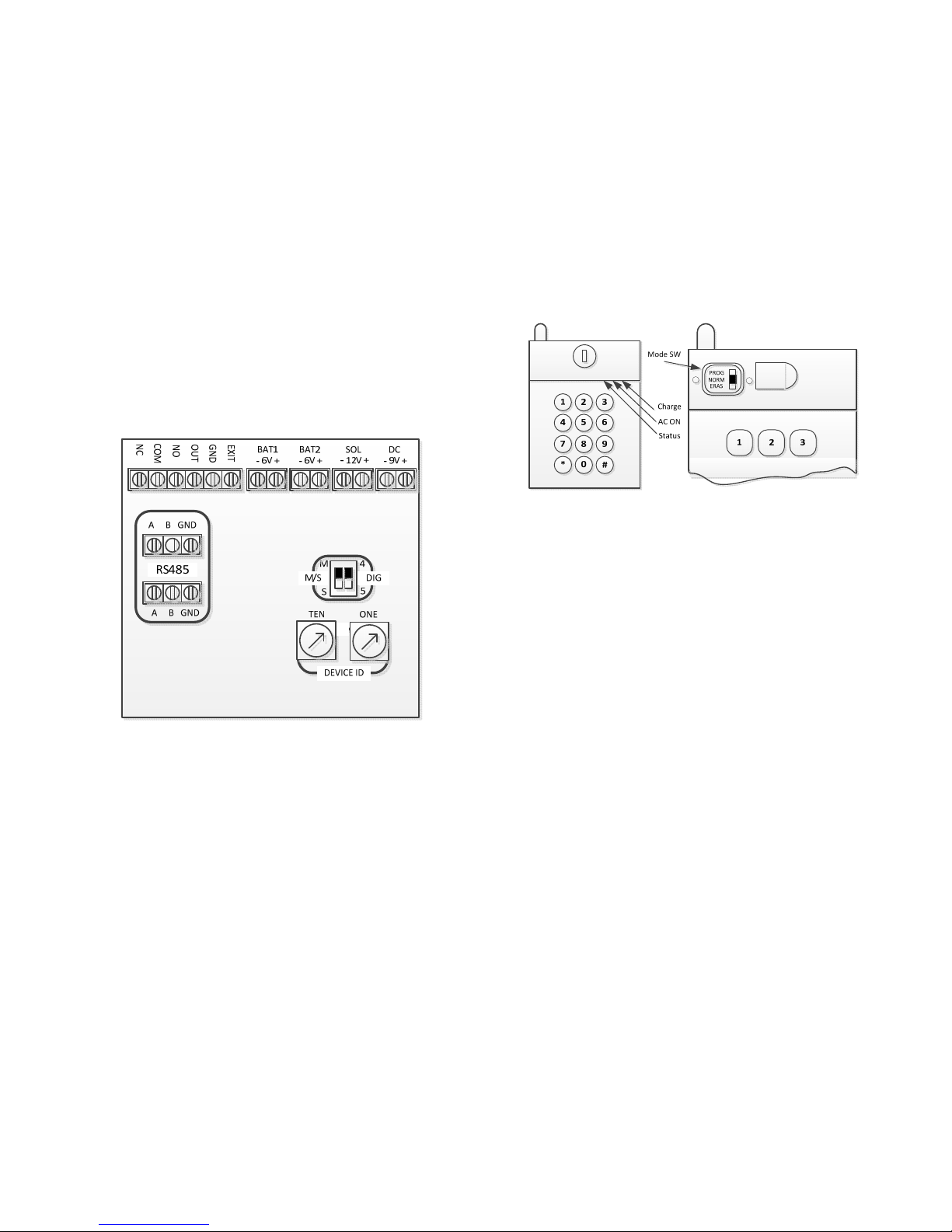
Note: only 4 digit mode applies to slave configuration.
b. Set master/slave by side “M/S” side DIP SW “M” or “S”.
3. Set the Slave Device ID
Set slave device ID by the 2 rotary decimal SW. set range 00-99
4. Indicator and Mode Switch Locations
See Fig.2.
Fig.1
Fig.2
OPERATIONS
1. Normal Mode
Selected by Mode SW (“NORM” position), "Red" light flash
a. To open primary gate, enter 4 or 5 key code.
b. To open secondary gate, enter #2 + 4 or 5 key code.
c. To hold open, enter #3xxxxx. xxxxx: 5 digit code
(00000-99999)
d. To release hold open, enter #3xxxxx again.
Status:
Beeping twice with green light: Success
Beeping once: Code is not match
2. Program Mode
Selected by Mode SW (“PRGM” position), "Yellow” light on.
Program Primary Key Code: Enter 4 or 5 key Code
Program Secondary Key Code: Enter #2 + 4 or 5 key Code
Status:

Beeping twice with green light: Program success
Beeping once with red light: Program fail
Program Command:
a. Control output strike duration (default 1s)
#4xx xx: 00-99s Primary control
#6xx xx: 00-99s Secondary control
b. Hold open code
#3xxxxx xxxxx: 5 digit code (00000-99999)
3. Erase Mode
Selected by Mode SW (“ERAS” position), "Yellow” light flash.
Erase Primary Key Code: Enter 4 or 5 key code
Erase Secondary Key Code: Enter #2 + 4 or 5 key code
#911 Erase all primary codes
#913 Erase hold open code
#914 Erase all secondary codes
Status:
Beeping twice with green light: Erase success
Beeping once with red light: Erase fail
4. Program RF Receiver:
Platinum RF receiver needs to be programmed to receive the RF
control code of this unit.
a. Program one key code (Ex. “1234”) on this unit per the steps in
section 2.
b. Set the unit back to “NORM” mode.
c. Open RF receiver cover and locate the programming button.
d. Place RF receiver close to this unit. Turn on RF receiver power.
e. Push the programming button in RF receiver.
f. When the programing LED is on in RF receiver, enter the key
code (“1234” ) on keypad.
g. When the programming is done, the programming LED will go
off.
h. Enter the key code (“1234”) again, and check the relay in
receiver is activated.
i. If the programming is unsuccessful, repeat step f to step i.
5. EXIT Input
“EXIT” input will activate control output at any time.
6. Slave Mode
Set DIP switch on board to “S” side. In “SLAVE” mode, all key
codes will be sent to master to process. Master will send “Open
Gate” command to slave upon valid key code. Device ID must be
set on the rotary “TEN” and “ONE” switches in multi slave
system.
Note: Each slave must be set to different device ID when they are
installed within one system.
 Loading...