

Platinum Access Systems BLSW2212, BLSW1016, BLSW814 Installation Instruction And Owenrs Manual

BLSW2212
BLSW2212 Manual_Layout 1 2/10/2014 5:11 PM Page 1

BLSW2212 Manual_Layout 1 2/10/2014 5:11 PM Page 2

TECHNICAL SUPPORT: (909) 259-6001
BLSW2212
3
Installation Instructions & Safety Information Manual
BLSW2212
Installation Instructions and Safety Information Manual:
Vehicular Gate Operator
Class I, Class II, Class III, and Class IV
Safety Information
Installation
Inductive Loops
Alarm Reset Switch
Plan of Installation
Electrical
Limit Switches
Primary/Secondary Connections
Loop Rack
Accessory Connections
Selectable Features
...............................................4-8
.............................................9-10
...........................................11-12
................................................13
..........................................14-17
..........................................18-19
..........................................20-21
...............................................22
...............................................23
..........................................24-27
..........................................28-30
BLSW2212 Manual_Layout 1 2/10/2014 5:11 PM Page 3

4
TECHNICAL SUPPORT: (909) 259-6001
BLSW2212
SAFETY INFORMATION
1. READ AND FOLLOW ALL INSTRUCTIONS MANUAL BEFORE ATTEMPTING ANY INSTALLATION.
2. Should never let children play with gate controls. Keep the remote control away from children.
3. Always keep people and objects away from the gate. “NO ONE SHOULD CROSS THE PATH OF
THE MOVING GATE”.
4. Check and test the gate operator monthly. The gate MUST reverse on contact with a rigid object
or when an object activates the non-contract sensors. After adjusting the force or the limit of travel, retest the gate operator. Failure to adjust and retest the gate operator properly can increase
the risk of injury or death.
5. 7KHJDWHV\VWHP0867EHPDLQWDLQHGSURSHUO\+DYHDTXDOL¿HGVHUYLFHSHUVRQLQVSHFWUHSDLURU
adjust your system if any unusual behavior is observed or suspected.
6. Some companies offer a scheduled preventive maintenance service.
7. '2127(;&(('WKHHTXLSPHQWVSHFL¿FDWLRQV
8. Insure a safe and proper installation.
9. ,QVWDOOWKLVHTXLSPHQWLQDFFRUGDQFHZLWKWKH8/VSHFL¿FDWLRQV
10. All installation MUST have secondary protection devices against entrapment, such as edge sensors and photo beams especially in places where the risk of entrapment is more likely to occur.
11. Gate is for vehicles only, a separate entrance for pedestrians is required.
12. SAVE THESE INSTRUCTIONS
SAFETY DEVICES:
1. Remove the Power Harness for the control board.
2. Check that all mounting hardware of the gate operator is properly tightened.
3. Ensure that the gate moves freely.
4. Check the battery for the following:
Battery connections must be free of corrosion.
Battery voltage must be 26.5 VDC minimum (fully charged battery).
5. Reconnect the Power Harness for the control board.
6. Make sure every installation has a minimum of one safety device (such as photo beams or loop
detector).
7. Check for Reverse Sensitivity.
8. Make sure that all areas around the gate are safe and secure.
WARNING – To reduce the risk of severe injury or death to person, please to follow these instructions:
BLSW2212 Manual_Layout 1 2/10/2014 5:11 PM Page 4
TECHNICAL SUPPORT: (909) 259-6001
BLSW2212
5
SAFETY INFORMATION
GENERAL SAFETY PRECAUTIONS WITH THE END-USER:
1. Instruct the end-user on how to safely operate all functions of the operator.
2. Instruct the end-user on how to safely use the Back-drive/ Emergency Release Options.
3. Clearly label and identify the circuit breaker for the operator and show the End-User the location of
the circuit breaker for the operator.
4. Thoroughly explain any and all warranties associated with the operator and installation.
5. These instructions must be kept for reference and forwarded to all possible future users of the system.
6. Provide the End-User with the “Home Owner’s Manual Guide”.
7. The Manufacturer cannot be held responsible for possible damage caused by improper, erroneous or
unreasonable use.
8. $OOFOHDQLQJPDLQWHQDQFHRUUHSDLUZRUNPXVWEHFDUULHGRXWE\TXDOL¿HGSHUVRQQHO
9. Failure to comply with the above may create a situation of danger.
10. All installation, maintenance and repair work must be documented and made available to the user.
Signature:
Contact:
Date:
Installer:
11. When gate is moving, do not:
a. Allow any children to play near the moving gate.
b. Attempt to obstruct the moving gate.
c. Allow any one get close to the moving gate.
12. Keep remote control, or any other gate operator remote devices away from the children.
13. If operator breakdown, or mulfunction, please disconnect the operator from the main power source.
Do not attempt to repair, or intervene directly by any one except a qualify personnel.
IMPORTANT INSTALLATION INSTRUCTIONS BY UL STANDARDS:
1. Install the vehicular gate operator only when:
a. The gate operator is appropriate for the construction of the gate and the usage class of the
gate.
b. All exposed pinch points are eliminated or guarded.
2. The gate operator is intended for installation only on gates used for vehicles. Pedestrians must be
supplied a separate access opening.
a. The pedestrian access opening shall be designed to promote pedestrian usage. Locate the gate
such that persons will not come in contact with the vehicular gate during the entire path of travel of
the vehicular gate.
3. The gate must be installed in a location so that enough clearance is supplied between the gate and
adjacent structures when opening and closing to reduce the risk of entrapment. Swinging gates shall
not open into public access areas.
(CONTINUED ON NEXT PAGE...)
WARNING – To reduce the risk of severe injury or death to person, please to follow these instructions:
BLSW2212 Manual_Layout 1 2/10/2014 5:11 PM Page 5

6
TECHNICAL SUPPORT: (909) 259-6001
BLSW2212
SAFETY INFORMATION
IMPORTANT INSTALLATION INSTRUCTIONS BY UL STANDARDS:
(CONTINUED FROM PREVIOUS PAGE)
4. The gate must be properly installed and work freely in both directions prior to the installation of
the gate operator. Do not over-tighten the arm clamp to compensate for a damaged or poorly
maintained gate.
5. The gate operator controls must be placed so that the user has full view of the gate area when
the gate is moving and away from the gate path perimeter.
6. Controls intended for user activation must be located at least six feet (6’) away from any moving
part of the gate and where the user is prevented from reaching over, under, around or through
the gate to operate the controls and shall be at least (5’) from the ground as to be out of reach of
children. Outdoor or easily accessible controls shall have a security feature to prevent unauthorized use. Also:
7. Ensure the Stop and/or Reset button must be located in the line-of-sight of the gate following
rules above. Activation of the reset control shall not cause the operator to start.
8. A minimum of two (2) Warning Placards shall be mounted, one on each side of the gate where
easily visible.
9. A gate operator utilizing a non-contact sensor such as an Photo beam or like in accordance
with section 31.1.1 of the UL325 standard:
a. Reference owner’s manual regarding placement of non-contact sensor for each type of ap plication.
b. Care shall be exercised to reduce the risk of nuisance tripping, such as when a vehicle trips
the sensor while the gate is still.
c. One or more non-contact sensors shall be located where the risk of entrapment or obstruction
exists, such as the perimeter reachable by a moving gate or barrier.
d. We recommend (EMX IRB-325) use as a fail safe photoeye to comply with UL325.
10. A gate operator utilizing a contact sensor such as an edge sensor or like in accordance with
section 31.1.1 of the UL325 standard:
a. A hard wired contact sensor shall be located and its wiring arranged so the communication
between the sensor and the gate operator is not subject to mechanical damage.
b. A wireless contact sensor such as the one that transmits radio frequency (RF) signals to the
gate operator for entrapment protection functions shall be located where the transmission of
the signals are not obstructed or impeded by building structures, natural landscaping or simi lar obstruction. A wireless contact sensor shall function under the intended end-use condi tions.
c. One or more contact sensors shall be located on the inside and outside leading edge of a
swing gate. Additionally, if the bottom edge of a swing gate is greater than 6 inches (152 mm)
above the ground at any point in its arc of travel, one or more contact sensors shall be lo cated on the bottom edge.
d. The following model(s) are comply with UL 325: Miller Edge model MGR20 or MGS20 edge
sensor.
WARNING – To reduce the risk of severe injury or death to person, please to follow these instructions:
BLSW2212 Manual_Layout 1 2/10/2014 5:11 PM Page 6
TECHNICAL SUPPORT: (909) 259-6001
BLSW2212
7
gate operator class categories and examples
CAUTION: To Reduce the Risk of Fire or Injury to Persons
Use only the type and size of batteries provided on an AC powered system: OUTDO-OT7-12
'RQRWGLVSRVHRIWKHEDWWHULHVLQ¿UH7KHFHOOVPD\H[SORGH&KHFNZLWKORFDOFRGHVIRUSRVVLEOH
disposal instructions.
Do not open or mutilate the operator batteries. Released electrolyte is corrosive and may cause
damage to the eyes or skin. It may be toxic if swallowed.
Exercise care in handling batteries in order not to short the battery with conducting materials such
as metal parts, rings, bracelets and keys.
Do not mix batteries of different sizes, from different manufacturers or of different ages in this
product. Replace both batteries as a set.
Observe proper polarity orientation between the batteries and charging circuit.
&KDQJHWKHRSHUDWRUEDWWHULHVSURYLGHGZLWKRULGHQWL¿HGIRUXVHZLWKWKLVSURGXFWRQO\LQDFFRU-
GDQFHZLWKWKHLQVWUXFWLRQVDQGOLPLWDWLRQVVSHFL¿HGLQWKLVRSHUDWRUPDQXDO
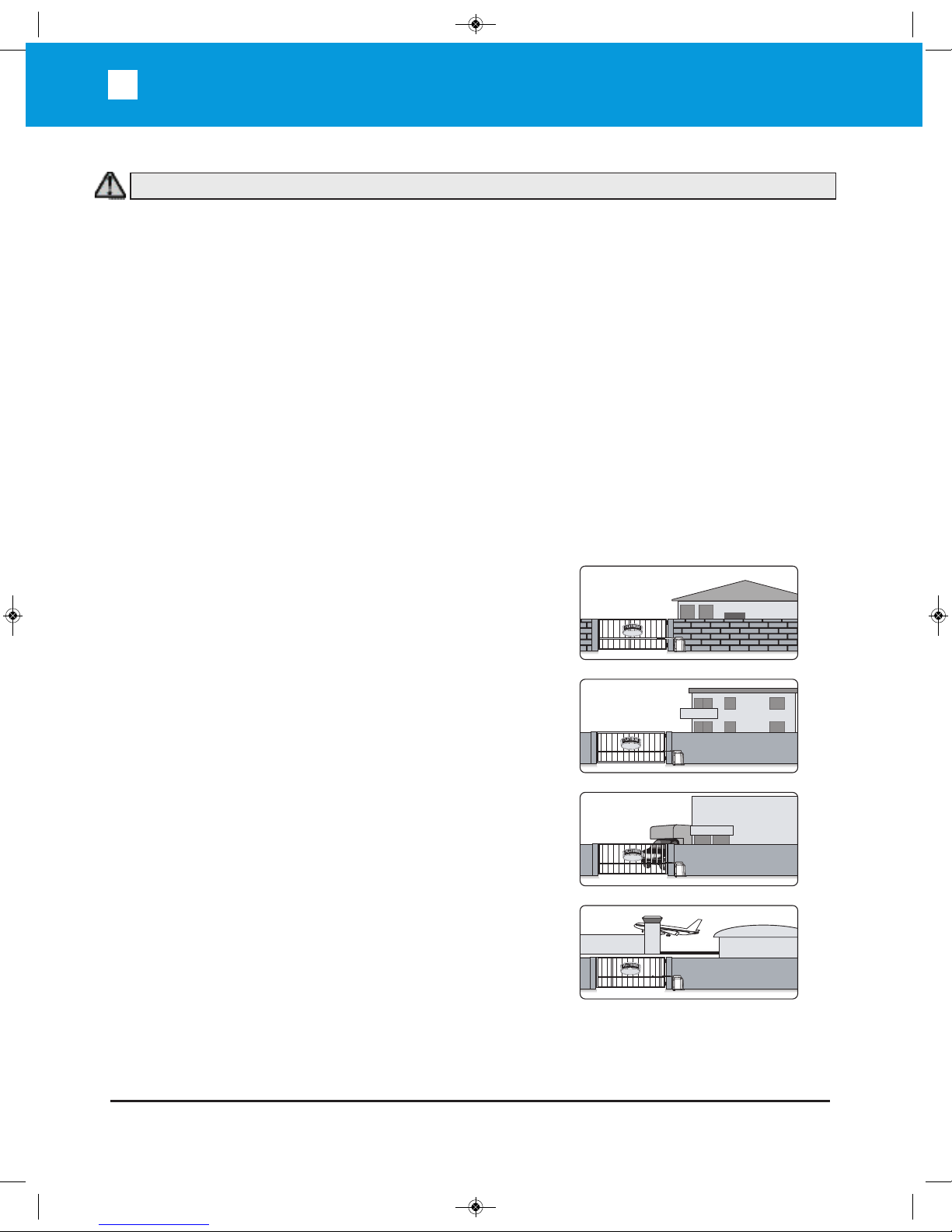
8/*DWH2SHUDWRU&ODVVL¿FDWLRQ
Install the gate operator only when: The operator is appropriate for the construction of the gate and the
Usage Class of the gate.
RESIDENTIAL VEHICULAR GATE OPERATOR
CLASS I – A vehicular gate operator (or system) intended for use In
a home of one-to four single family dwelling, or a garage or parking
area associated there with.
COMMERCIAL/GENERAL ACCESS VEHICULAR GATE OPERATOR
CLASS II – A vehicular gate operator (or system) intended for use in
a commercial location or building such as a multi-family housing unit
¿YHRUPRUHVLQJOHIDPLO\XQLWVKRWHOJDUDJHVUHWDLOVWRUHRURWKHU
building servicing the general public.
INDUSTRIAL/LIMITED ACCESS VEHICULAR GATE OPERATOR
CLASS III – A vehicular gate operator (or system) intended for use
in an industrial location or building such as a factory or loading dock
area or other locations not intended to service the general public.
RESTRICTED ACCESS VEHICULAR GATE OPERATOR
CLASS IV – A vehicular gate operator (or system) intended for use in
a guarded industrial location or building such as an air port security
area or other restricted access locations not servicing the general
public, in which unauthorized access is prevented via supervision by
security personnel.
HOTEL
FACT ORY
DOCK
HANGAR 00
WARNING – To reduce the risk of severe injury or death to person, please to follow these instructions:
BLSW2212 Manual_Layout 1 2/10/2014 5:11 PM Page 7
8
TECHNICAL SUPPORT: (909) 259-6001
BLSW2212
SAFETY INFORMATION
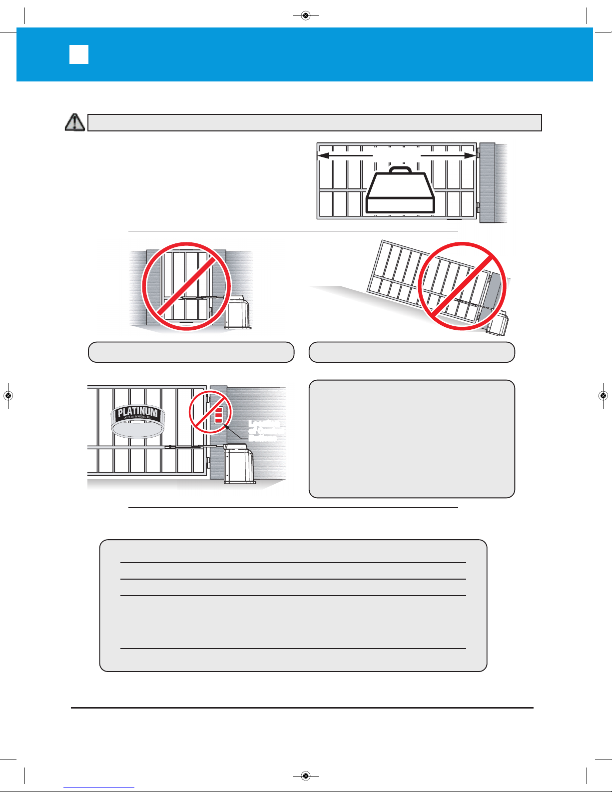
FOR USE WITH GATES OF A
MAXIMUM OF 12 FT IN LENGTH
AND 2200 LBS. IN WEIGHT
Specifications
This is NOT a pedestrian gate operator
Do NOT Install the gate operator to lift gates
Control Buttons Location:
1. Within sight of the gate,
2. At a minimum height of 5 feet so
small children are not able to
reach it, and make sure it is
away from all moving parts of
the gate.
2200 lb.
MAX.
12'-0"
C
LOSE
S
TOP
O
PEN
Location
of Control
Buttons
Location
of Control
Buttons
Maximum Gate Length:
Maximum Gate Weight:
Maximum Aperture Angle:
Power Requirements:
Operating Temperature:
12 feet
2200 lbs
120 deg.
120 VAC Single Phase at 2 Amps
or
220 VAC Single Phase at 1 Amp
-20°C (-4°F) to 70°C (158°F)
WARNING – To reduce the risk of severe injury or death to person, please to follow these instructions:
BLSW2212 Manual_Layout 1 2/10/2014 5:11 PM Page 8
TECHNICAL SUPPORT: (909) 259-6001
BLSW2212
9
INSTALLATION
Contact Sensor (Edge) Installation:
Secondary Entrapment Protection
One or more contact sensors shall be located on the inside and outside leading edge of a swing gate.
Also if the bottom edge of a swing gate is more than 6” (152mm) above the ground at any point in its
travel on or more sensors shall be located to protect from the bottom edge.
A wireless contact sensor such as one that transmits radio frequency signals to the gate
operator for entrap-ment protection functions shall be located where the transmission of the
signals are not obstructed or im-peded by building structures, natural landscaping or similar
obstruction. A wireless contact sensor shall function under the intended end-use conditions.
A hardwired contact sensor shall be located and its wiring arranged so that the communica-
tion between the sensor and the gate operator is not subjected to mechanical damage.
Use only Miller Edge 3-sided activation type MGR20 or MDS20 to comply with UL325
3-Sided Edge Sensor
3-Sided Edge Sensor
When manual operation is required:
1. Remove the Hat
2. Lift the Locking Handle.
3. Remove the Clutch Key
To reengage the gate operator:
1. Align the Clutch and the notches on the
Output Shaft.
2. Insert the Clutch Key.
3. Push down the Locking Handle.
4. Reattach the Hat.
Attention: Lock and release operations MUST
be performed with motor NOT RUNNING.
Manual Release
Locking Handle
(in Unlocked
Position)
Note: This type of installation DOES NOT reverse the gate all the way back to its limits when the photobeam is obstructed. This installation is only to protect against entrapment and to comply with UL325.
WARNING – To reduce the risk of severe injury or death to person, please to follow these instructions:
BLSW2212 Manual_Layout 1 2/10/2014 5:11 PM Page 9

10
TECHNICAL SUPPORT: (909) 259-6001
BLSW2212
INSTALLATION
Non-Contact Sensors (Photoelectric Sensors) Installation:
One or more non-contact sensors shall be located where the risk of entrapment or obstruction exists,
such as the perimeter reachable by a moving gate or barrier.
Install photoelectric sensors to protect
against any entrapment or safety conditions
encountered in your gate application.
We recommend the use of EMX IRB-325
photoeyes to comply with UL325.
Open Position
Photo Beam Device
Reflector
Potential Entrapment Area
Consult the UL325 device installation manual for more detail information about the usage,
installation and maintenance of this device.
Note: This type of installation DOES NOT reverse the gate all the way back to its limits when the photobeam is obstructed. This installation is only to protect against entrapment and to comply with UL325.
TX
E
MX Model
IRB-325
S
hown
Connection ‘1’ (C1)
Connection ‘2’ (NC1)
WARNING – To reduce the risk of severe injury or death to person, please to follow these instructions:
BLSW2212 Manual_Layout 1 2/10/2014 5:11 PM Page 10

TECHNICAL SUPPORT: (909) 259-6001
BLSW2212
11
Installation: Inductive Loops
Inductive Loops Installation:
Safety loops allows the gate to stay open when vehicles are obstructing the gate path.
If the gate is longer than the vehicles that pass through it a center loop is recommended and should
be installed. A center loop prevents the gate from closing when a vehicle is between the safety loops.
Safety loops are required when using a center loop. See Loop Wiring.
Outside
Inside
O
u
t
si
d
e
S
a
f
e
t
y
L
o
o
p
Ce
n
t
e
r
L
o
o
p
I
n
s
id
e
Sa
f
e
t
y
L
o
o
p
Exi
t
Lo
o
p
5'
5' 5'
XX
5'
Gate in Open Position
Even with Open Gate
Outside
Safety
Loop
Outside Inside
Center
Loop
Inside
Safety
Loop
Exit
Loop
Check with local regulations and accepted best practice requirements for every installation.
S
WARNING – Consult the installation instructions from the loop detector manufacturer. The following
statements are provided as a guide but different requirements may be required by the vehicular loop
detector manufacturer.
BLSW2212 Manual_Layout 1 2/10/2014 5:11 PM Page 11

12
TECHNICAL SUPPORT: (909) 259-6001
BLSW2212
Installation: Inductive Loops
WARNING – This product is an accessory or part of a system. Always read and follow the manufacturer’s instructions for the equipment before connecting this product. Comply with all applicable codes
and safety regulations. Failure to do so may result in damage, injury or death.
Inductive Loops Installation:
Recommended # of Turns
Perimeter in Feet # of Turns
10 5
20 4
30-40 3
50-100 2
General Installation Guidelines
Lead-in wire (wire from loop to
detector) must be must be twisted
a minimum of 6 turns/ foot to
avoid the effects of noise or other
interference.
Detection height is approximately 70%
of the shortest side of the loop.
1" Min.
Backer-Rod
Vehicular Loop
Detector Wire
Sealant
Saw Cut
Concrete Slab Cross View
1 - 1 1/4in. PVC Pipe
Steel Rebar
Concrete Slab Cross View
Vehicular Loop
Detector Wire
Existing Surface
Vehicular Loop
Detector Wire
Sand filled Saw Cut
Saw Cut
Asphalt Re-surface
New Asphalt
New Slab Pour
Ty-wrap 1 1/4” PVC Pipe to the top of the rebar in the
size and configuration of the loop (i.e. 4ft x 8ft). Then
ty-wrap the loop to the top of the PVC frame. This
stabilizes the loop during the pour and separates it
from the rebar.
Saw Cut Existing Surface
Cut “ deep into the existing surface, place a 45° cut
at the corners to prevent sharp edges from damaging
the loop wire. Notch out for the ”T” connection where
the lead wire connects to the loop. Remove all debris
from the finished cut with compressed air. Place the
loop into the saw cut. Place backer material into the
saw cut over the loop wire and pack tightly. Place a
high quality sealer over the saw cut to seal the
surface.
Resurface Asphalt
Saw cut the existing surface 3/4” deep and place a
45° cut at the corners to prevent sharp edges from
damaging the loop wire. Remove all debris from the
finished cut with compressed air. Place sand over the
loop wire to the surface and pack tightly. Lay new
asphalt.
BLSW2212 Manual_Layout 1 2/10/2014 5:11 PM Page 12

TECHNICAL SUPPORT: (909) 259-6001
BLSW2212
13
Installation: Alarm Reset Switch & Warning Placards
Alarm Reset Switch Installation: (UL 325 standard requires)
An audible alarm to go off after two consecutive events detected by the primary entrapment protection
of the gate operator. The audible alarm will continue to sound for 5 minutes or until a stop command
gets actuated. The Stop command can be actuated in two different forms.
1. The Built in Stop switch on the Control Box.
2. The External Stop button within the sight of the gate, away from moving parts of the gate and out
of reach of children.
S
T
O
P
COM
N.C.
STOP
6'
5'
Minimum
Manual Stop
Button
Warning Placard Installation:
All Warning Sings and Placards must be mounted where visible in the area of the gate. A minimum
of two (2) Warning Placards shall be mounted. (One on each side of the gate).
WARNING – To reduce the risk of severe injury or death to person, please to follow these instructions:
BLSW2212 Manual_Layout 1 2/10/2014 5:11 PM Page 13

14
TECHNICAL SUPPORT: (909) 259-6001
BLSW2212
PLAN OF INSTALLATION
Plan of Installation:
BC
C = A + 12"
Inside
Outside
G
ate in Closed Position
E
E
=
(L x
0
.
4
)
D
=
(
L
x
0
.
6
)
L
=
8
7
”
M
a
xi
mu
m
w
i
t
h
Pl
at
i
num
A
r
m
A
F
G
a
t
e
in
O
p
e
n
P
o
sitio
n
D
L
The gate must be installed in a location so that enough clearance is supplied between the
gate and adjacent structures when opening and closing to reduce the risk of entrapment.
Swinging gates shall not open into public access areas.
Figure A
The installation shown using the
Straight Arm Secondary Extension can
NOT be back-driven. If a back-driven
installation is required, an Elbow Arm
Secondary Extension can be used.
Contact Platinum Access for availability.
*Note: The dimensions provided are
just a guideline. Each site may have
different geometries or possibilities of
installation. The key for installation is
to have "D" longer than "E" and to
adjust the arms such that the arm is
straight at the closed position.
Place the operator at the
desired location and check
the measurements of A
and B.
BLSW2212 Manual_Layout 1 2/10/2014 5:11 PM Page 14

TECHNICAL SUPPORT: (909) 259-6001
BLSW2212
15
PLAN OF INSTALLATION
Plan of Installation (continued):
Drill for a 1/2" x 3-1/2"
Red Head Anchor
(4) Places
23-1/4"
30"
7-5/8"
2-7/16"
10"
3-1/4"
6" Minimum
20"
Center of Output Shaft
Gate Operator
Concrete Pad
Gate Operator
Concrete Pad
Operator
Cover
Grade Level
(
See Note 2 below)
Operator
Chassis
Secondary Extension
Dimension D
(see Fig. A)
Dimension E
(see Fig. A)
Primary Extension
Pivot Bracket
Arm Assembly
Concrete Pad
Platinum Access Systems can supply an Elbow Arm
Secondary Extension (Part # PA-EA100) to make the unit
backdrivable. Contact Platinum Access for availability.
(Platinum Part # PA-EA100)
1.
Follow the local building code to determine the requirement of the concrete pad.
2. We recommend the Pad measurements should be at least 28” long, 20” wide,
and 24” deep to ensure the stable operation of the operator, and a minimum
of 4” above level grade to avoid any flooding of the operator.
3. To support the weight of the gate, we recommend the path of the track should be
at least 10” wide and 6” deep.
BLSW2212 Manual_Layout 1 2/10/2014 5:11 PM Page 15

16
TECHNICAL SUPPORT: (909) 259-6001
BLSW2212
PLAN OF INSTALLATION
Plan of Installation (continued):
Remove Excess
Extension Tube
STEP 1
Release the clutch (see pg. 7) and cut the
extension arms according to the desired plan
of installation (Figure A on pg. 12).
Note: Leave extra material when cutting the
extension arms to allow for any added
adjustment.
STEP 2
With the gate in the closed position, place
the pieces of the articulated arm. Make
certain the dimensions correspond to the
plan of installation. To aid in the preinstallation process, use C-clamps or tackweld pieces.
STEP 3
With the clutch released, manually position
the gate from the completely open to the
completely closed position. Confirm that the
gate/arm combination provides the desired
operation and that the arm does not bind in
its movement (especially in the open
position).
Note: The speed of the gate operation is
based on the total travel angle of the primary
arm on the output shaft. The smaller the angle,
the quicker the gate opens and closes.
CAUTION
Do not weld the bar or backing plate
to only a few gate posts. Mounting
bar must be welded to a frame
segment that runs the full length of
the gate to prevent damage to the
gate operator.
BLSW2212 Manual_Layout 1 2/10/2014 5:11 PM Page 16

TECHNICAL SUPPORT: (909) 259-6001
BLSW2212
17
PLAN OF INSTALLATION
Plan of Installation (continued):
Adjust the
Opposite Bolt
Tighten the
Arm Clamp
Insert
Output Key
STEP 5
Upon test of the installation, loosen the Arm
Clamp and rotate it until it lines up with the
notches in the Output Key.
Insert the Output Key.
STEP 6
Check the Arm Clamp adjustment. The Arm
Clamp is shipped factory adjusted. The Arm
Clamp must be tight enough to prevent slippage in normal operation.
Check the tightness of the Arm Clamp:
A. Remove the Output Key from the Arm
Clamp.
B. Attempt to manually move the gate.
C. If slippage occurs:
1. Loosen the Locking Handle
2. Tighten the opposite bolt.
3. Tighten the Locking Handle
4.
Check the tightness of the Arm Clamp
again.
STEP 4
Once satisfied with the arrangement of the
articulated arm and bracket, weld all pieces
securely.
Paint the arm to preserve it from rusting.
BLSW2212 Manual_Layout 1 2/10/2014 5:11 PM Page 17

18
TECHNICAL SUPPORT: (909) 259-6001
BLSW2212
Installation: ElecTrical
Electrical Installation:
To help protect the equipment from lightning and power
surges and to protect persons from shock hazard the
Operator must be grounded. The earth ground rod must
be located within 3 feet from the gate operator. Use the
proper type earth ground rod for your local area. The
ground wire must be a single, whole piece of wire. Never
splice two wires for the ground wire. If you should cut the
ground wire too short, break it, or destroy its integrity,
replace it with a single wire length. Prevent unnecessary
turns or loops in ground wires.
The Gate Operator requires a single phase AC line to
operate and charge the batteries.
1. Turn off the supply for the circuit you are using.
2. Select the proper voltage on the power board.
3. Connect the incoming power wires to the proper
terminals.
4. Turn on supply power and check that AC ON and
CHARGE LED are lit.
Ground Rod
Earth Ground
To
Transformer
Neutral
Power Ground
115V/230V
Power Switch
Earth Ground
Hot
:$51,1*±'RQRWFRQQHFWWKHSRZHUKDUQHVVWRWKHERDUGXQWLOWKHLQVWDOODWLRQLVUHDG\IRUYHUL¿FDWLRQ
Power Harness
White
Green
Red
Black
The power receptacle has been left unconnected till the installer decides what voltage to use.
Connect to 120VAC only
BLSW2212 Manual_Layout 1 2/10/2014 5:11 PM Page 18

TECHNICAL SUPPORT: (909) 259-6001
BLSW2212
19
Installation: ElecTrical
Connecting Power:
Connect the LIMIT harness to J14, and MOTOR CTL harness to J4.
On the OPEN DIR switch:
Select “RIGHT” to open right.
Select “LEFT” to open left.
White
Green
Black
Red
OPEN LEFT OPEN RIGHT
BLSW2212 Manual_Layout 1 2/10/2014 5:11 PM Page 19

20
TECHNICAL SUPPORT: (909) 259-6001
BLSW2212
Installation: LIMIT SWITCH SET-UP
Limit Switch Set-Up:
STEP 8
Install the Cover by carefully
slipping the front half over the Limit
Switches and Cam Wheel., then fitting the
back cover in place. Latch the hasps on both
sides of the Cover.
STEP 7
A. Loosen the screws on the Limit Switch Cams.
B. Remount the articulated arm, making sure
the cam wheel pin is engaged with the
clutch.
C. Move the gate manually to the closed position.
D. Move the Limit Switch Cams on the Cam
Wheel to actuate each limit switch.
E. Slightly tighten the screw on the Limit
Switch Cam.
F. Move the gate manually to the open
position. Repeat steps a, b and c for the
other cam.
G. Run the unit 2 full cycles without
interruption (from limit to limit) to
execute a “Learn Cycle.”
Gate Opens to Right
Left Limit Switch Open limit
Right Limit Switch Close limit
Gate Opens to Left
Left Limit Switch Close limit
Right Limit Switch Open limit
Left Limit Switch
Right
L
imit
S
witch
Limit Ring
Limit Switch Cam
Cam Wheel
Set Left Cam
In This Direction
Set Right Cam
In This Direction
BLSW2212 Manual_Layout 1 2/10/2014 5:11 PM Page 20

TECHNICAL SUPPORT: (909) 259-6001
BLSW2212
21
Installation: LIMIT SWITCH SET-UP
Limit Switch Set-Up (continued):
LIMIT SWITCH
CONNECTIONS
The Limit Switches are
pre-wired. Should the
wires become disconnected, use this
diagram to reconnect
them.
Fast
Slow
Slow
OPENING/CLOSING SETUP
1. Setup the limit switches manually at the
desired open and close position.
2. Allow the gate operator to run a full open
and close cycle (from limit to limit) without
interruption.
Note: During the first full open and close
cycle, the gate operator will run at low speed.
During subsequent cycles, the gate operator
will speed up at start and slow down prior to
reaching its limits.
3. Verify that the gate opens and closes to
the desired position.
Note: When slightly adjusting the open or close limit position(s), the operator will automatically adapt the changes. When relearning is needed, push and hold "RESET"
button for 3 second, the machine will return to original state, and be ready for learning.
B
la
c
k
R
e
d
G
r
een
W
hi
t
e
Right Limit
Switch
Left Limit
Switch
BLSW2212 Manual_Layout 1 2/10/2014 5:11 PM Page 21

22
TECHNICAL SUPPORT: (909) 259-6001
BLSW2212
Installation: Primary/Secondary Connections
Electrical Installation - Primary/Secondary:
The control board provides a connector for Primary/Secondary connectivity. This
connector will allow synchronized operation with a second gate operator.
Shielded Cable (#PA-PSC100)
NOTE: Use 16
Guage Wire for
runs up to 100’
Conduit
Shield Wire
Caution – Do not run Primary/Secondary communication
cable (Model #PA-PSC100) in the same conduit as the
power supply (120-220V) cable.
Inside
Outside
PrimarySecondary
Interconnecting Conduit
Blk\Wht
Green
Red
SilverSilver
Blk\Wht
Green
Red
Note: It is recommended to connected all external devices and set timer on the Primary unit. Timer
setting on Secondary unit will be ignored.
BLSW2212 Manual_Layout 1 2/10/2014 5:11 PM Page 22

TECHNICAL SUPPORT: (909) 259-6001
BLSW2212
23
Installation: Loop Rack
Loop Rack Installation:
Exit
Safety
Inside
Outside
Center
Exit
Center
Gnd
Safety
Twist Wire Outside the
L
oop 6 Twists/Foot
Until Its Connection
to the Loop Rack
Inside Safety
Loop
Center
Loop
Outside Safety
Loop
Exit
Loop
Loop Connector
Control Board
Connector
Loop Rack (#GOC-LDR)
Safety
Exit
Center
28V
Gnd
Gnd
Gnd
BLSW2212 Manual_Layout 1 2/10/2014 5:11 PM Page 23

24
TECHNICAL SUPPORT: (909) 259-6001
BLSW2212
Installation: Accessory Connections
Accessory Connections:
Outside
Open
Commands
Keypad
Fire
Override
Safety Connections
Edge Sensor
P
hoto
B
eam
TX
C
enter
Loop
D
etector
Safety
Loop
D
etector
Photo
Beam
TX
Reopen Photo Beam
Note: Installing the photo beam in this way,
allows the gate to re-open all the way upon
obstruction of the photo-beam.
The optional PBD connector provides a
controlled power supply for Photo Beam.
The power will be turned off when gate is
in close position to save battery.
Option for
Solar Power
Input ONLY
To decrease the possibility of vehicle entrapment on the gate, vehicle
loop detectors need to be installed. The edge sensor and the photoelectric beam can be used for secondary entrapment protection on
every installation to prevent pedestrian or animal entrapment. These
accessories must be UL325 compliant devices.
BLSW2212 Manual_Layout 1 2/10/2014 5:11 PM Page 24

TECHNICAL SUPPORT: (909) 259-6001
BLSW2212
25
Installation: Accessory Connections
ACCESSORY CONNECTIONS (continued):
Need to verify the proper connections before connecting the Radio Receiver.
The maximum voltage that the control board / battery can provide is about 28V
for external accessories. If there is an electrical shot in the power to the
accessories, the control board will protect itself by shutting down and will
remain shut down until the short is fixed.
Radio Receiver
Two modes of operation that a radio receiver
can control the gate:
Open-Close
By having the radio receiver connected as
illustrated and with the Timer OFF:
Every command of the radio transmitter
will control the gate as follow:
A. First command opens the gate
B. Second command CLOSE the gate if at
open position
C. Third command OPEN the gate
D. Any subsequent commands will continue
in the same order to control the gate.
This type of configuration is not recommended for a commercial installations.
Open Only
By having the radio receiver connected as
illustrated and with the Timer ON:
Each command of the radio transmitter is
ALWAYS AN OPEN COMMAND to the gate.
RED
BLACK
GRAY
GRAY
MS-109950
Receiver
Linear MS-109950
Installation Diagram
BLSW2212 Manual_Layout 1 2/10/2014 5:11 PM Page 25

26
TECHNICAL SUPPORT: (909) 259-6001
BLSW2212
Installation: Accessory Connections
Accessory Connections (continued):
Solenoid Connection
The solenoid power connection must be
provided an external power source. This will
prevent damage to the battery in the event of
a line power failure.
Guard Station
This will control the gate operator to Open,
Stop, and Close the gate. The switches for
Open and Close must be normally open
type. The switch for Stop must be normally
close type. They all can be using the same
common ground. The control switch box
should be within sight of the gate, out of
reach of children, and away from moving
parts of the gate.
If no guard station or STOP switch is
installed, a jumper must be inserted between
“STOP(NC)” and “GND” pins.
OPEN
S
TOP
GND
STOP
OPEN
CLOSE
CLOSE
BLSW2212 Manual_Layout 1 2/10/2014 5:11 PM Page 26

TECHNICAL SUPPORT: (909) 259-6001
BLSW2212
27
Installation: Accessory Connections
The Magnetic Lock power connection must be provided an
external power source. This will prevent damaging the battery
in the event of line power failure.
Green
Black
White
Red
(Supplied with Lock Kit)
24VDC
Magnetic Lock
(
#PA-MAG13)
(Supplied with
Lock Kit)
Locks
OPTIONAL ACCESSORY- part # (PA-MAG13).
ACCESSORY CONNECTIONS (continued):
BLSW2212 Manual_Layout 1 2/10/2014 5:11 PM Page 27

28
TECHNICAL SUPPORT: (909) 259-6001
BLSW2212
Installation: Selectable Features
OPEN ON POWER FAIL:
The Auto-Open feature in Platinum Access Systems Gate Operators enables the following
functionality in the event of power failure:
a. Open the gate in case of power failure (120 or 220 VAC).
b. Keep the gate at the open position as long as the there is no power.
c. Resume to normal operation when the power has been restored.
All accessories and safety devices are functional. The only function disabled is the close command.
ADVANCING LOCK SELECT:
PRIMARY/SECONDARY OPERATOR SELECT:
I
Auto-Open
To enable the Auto-Open feature: Select the
DIP switch to AUTO OP position.
ADV MLOK
To set the maglock to be engaged before the
gate reaches the close or open position:
Select the DIP switch to ADV MLOK position.
Primary/Secondary
To set the operator to Secondary: Select the
DIP switch to SECONDARY position. Recycle
power to make the new setting effective.
To set the operator to Primary: Select the DIP
switch to PRIMARY position. Recycle power
to make the new setting effective.
BLSW2212 Manual_Layout 1 2/10/2014 5:11 PM Page 28

TECHNICAL SUPPORT: (909) 259-6001
BLSW2212
29
Installation: Selectable Features
CLOSE TIMER:
LEAF DELAY:
INSTANT
REVERSING
SENSOR:
Close Timer
The Close Timer will close the gate a set time
after the vehicle clears the gate area. This is
adjustable from 3 to 60 seconds.
Leaf Delay
An Overlap Delay has been provided for
biparting gates that have an emblem or
maglock for example. It will provide up to a 3
second delay on primary or secondary
operator.
Instant Reversing Sensor
The Obstruction Sensor needs to be adjusted
to compensate for the installation and gate
weight. The overload adjustment is provided
to set the gate sensitivity.
a) If the gate reverses by itself or stops in
midcycle, it is too sensitive.
b) If the gate hits an object and does not
reverse or stop, it is not sensitive
enough.
c) Clockwise increases sensitivity, counter clockwise decreases sensitivity.
Test and adjust
for proper reversing pressure
(Note: When unit alarms, push “STOP” or
“RESET” button will clear the alarm)
BLSW2212 Manual_Layout 1 2/10/2014 5:11 PM Page 29

30
TECHNICAL SUPPORT: (909) 259-6001
BLSW2212
Installation: Selectable Features
SOLAR INSTALLATION:
Step 1
A 24V solar panel or two 12V solar panels
with minimum 80 Watts capacity is required.
Step 2
Connect the solar panel cables to the power
harness as shown. Make sure you cut the
wires coming from the toroidal transformer.
+
–
+
–
Connect To Solar
Regulator Input
24 VDC
Panel
12 VDC
Panels
FAIL SAFE/SECURE:
Fail Safe/Secure
On = Fail Safe
Off = Fail Secure
Fail/Safety
(Input)
ON
ON
ON
ON
OFF
OFF
OFF
OFF
Battery
Detection
Normal
Normal
Low/OFF
Low/OFF
Normal
Normal
Low/OFF
Low
AC
Detection
Normal
OFF
Normal
OFF
Normal
OFF
Normal
OFF
Output
Secure
Fail Safe
Fail Safe
Fail Safe
Secure
Fail Secure
Fail Secure
Fail Secure
Note: When the output is "Fail Safe", there is
less resistance to push the gate open manually.
For solar installation assistance please call technical support at 909-259-6001
BLSW2212 Manual_Layout 1 2/10/2014 5:11 PM Page 30

BLSW2212 Manual_Layout 1 2/10/2014 5:11 PM Page 31

PLATINUM ACCESS SYSTEMS
™
1725 E. Grevillea Court, Ontario, CA 91761
Phone: (855) 466-8686 I Fax: (909) 923-7890
© 2013 Platinum Access Systems, Inc. All Rights Reserved.
www.PlatinumASI.com
BLSW2212 Manual_Layout 1 2/10/2014 5:11 PM Page 32
 Loading...