

Platinum Access Systems BLSW1016 Installation Instruction And Owenrs Manual
BLSW1016

3
Installation Instructions & Safety Information Manual
BLSW1016
Installation Instructions and Safety Information Manual:
Vehicular Gate Operator
Class I, Class II, Class III, and Class IV
Safety Information
Installation
Inductive Loops
Alarm Reset Switch
Plan of Installation
Electrical
Limit Switches
Primary/Secondary Connections
Loop Rack
Accessory Connections
Selectable Features
Maintenance
Gate Operator Trouble Shooting Procedure
Part
...............................................4-8
.............................................9-10
...........................................11-12
................................................13
..........................................14-17
..........................................18-19
...............................................20
...............................................22
...............................................23
..........................................24-27
..........................................28-30
...............................................31
...........................................32-33
...............................................34
BLSW1016 Manual_Layout 1 5/8/2015 5:06 PM Page 3

4
SAFETY INFORMATION
1. READ AND FOLLOW ALL INSTRUCTIONS MANUAL BEFORE ATTEMPTING ANY INSTALLATION.
2. Should never let children play with gate controls. Keep the remote control away from children.
3. Always keep people and objects away from the gate. “NO ONE SHOULD CROSS THE PATH OF
THE MOVING GATE”.
4. Check and test the gate operator monthly. The gate MUST reverse on contact with a rigid object
or when an object activates the non-contract sensors. After adjusting the force or the limit of travel, retest the gate operator. Failure to adjust and retest the gate operator properly can increase
the risk of injury or death.
5. 7KHJDWHV\VWHP0867EHPDLQWDLQHGSURSHUO\+DYHDTXDOL¿HGVHUYLFHSHUVRQLQVSHFWUHSDLURU
adjust your system if any unusual behavior is observed or suspected.
6. Some companies offer a scheduled preventive maintenance service.
7. '2127(;&(('WKHHTXLSPHQWVSHFL¿FDWLRQV
8. Insure a safe and proper installation.
9. ,QVWDOOWKLVHTXLSPHQWLQDFFRUGDQFHZLWKWKH8/VSHFL¿FDWLRQV
10. All installation MUST have secondary protection devices against entrapment, such as edge sensors and photo beams especially in places where the risk of entrapment is more likely to occur.
11. Gate is for vehicles only, a separate entrance for pedestrians is required.
12. SAVE THESE INSTRUCTIONS
SAFETY DEVICES:
1. Remove the Power Harness for the control board.
2. Check that all mounting hardware of the gate operator is properly tightened.
3. Ensure that the gate moves freely.
4. Check the battery for the following:
Battery connections must be free of corrosion.
Battery voltage must be 26.5 VDC minimum (fully charged battery).
5. Reconnect the Power Harness for the control board.
6. Make sure every installation has a minimum of one safety device (such as photo beams or loop
detector).
7. Check for Reverse Sensitivity.
8. Make sure that all areas around the gate are safe and secure.
WARNING – To reduce the risk of severe injury or death to person, please to follow these instructions:
BLSW1016 Manual_Layout 1 5/8/2015 5:06 PM Page 4
5
SAFETY INFORMATION
GENERAL SAFETY PRECAUTIONS WITH THE END-USER:
1. Instruct the end-user on how to safely operate all functions of the operator.
2. Instruct the end-user on how to safely use the Back-drive/ Emergency Release Options.
3. Clearly label and identify the circuit breaker for the operator and show the End-User the location of
the circuit breaker for the operator.
4. Thoroughly explain any and all warranties associated with the operator and installation.
5. These instructions must be kept for reference and forwarded to all possible future users of the system.
6. Provide the End-User with the “Home Owner’s Manual Guide”.
7. The Manufacturer cannot be held responsible for possible damage caused by improper, erroneous or
unreasonable use.
8. $OOFOHDQLQJPDLQWHQDQFHRUUHSDLUZRUNPXVWEHFDUULHGRXWE\TXDOL¿HGSHUVRQQHO
9. Failure to comply with the above may create a situation of danger.
10. All installation, maintenance and repair work must be documented and made available to the user.
Signature:
Contact:
Date:
Installer:
11. When gate is moving, do not:
a. Allow any children to play near the moving gate.
b. Attempt to obstruct the moving gate.
c. Allow any one get close to the moving gate.
12. Keep remote control, or any other gate operator remote devices away from the children.
13. If operator breakdown, or mulfunction, please disconnect the operator from the main power source.
Do not attempt to repair, or intervene directly by any one except a qualify personnel.
IMPORTANT INSTALLATION INSTRUCTIONS BY UL STANDARDS:
1. Install the vehicular gate operator only when:
a. The gate operator is appropriate for the construction of the gate and the usage class of the
gate.
b. All exposed pinch points are eliminated or guarded.
2. The gate operator is intended for installation only on gates used for vehicles. Pedestrians must be
supplied a separate access opening.
a. The pedestrian access opening shall be designed to promote pedestrian usage. Locate the gate
such that persons will not come in contact with the vehicular gate during the entire path of travel of
the vehicular gate.
3. The gate must be installed in a location so that enough clearance is supplied between the gate and
adjacent structures when opening and closing to reduce the risk of entrapment. Swinging gates shall
not open into public access areas.
(CONTINUED ON NEXT PAGE...)
WARNING – To reduce the risk of severe injury or death to person, please to follow these instructions:
BLSW1016 Manual_Layout 1 5/8/2015 5:06 PM Page 5

6
SAFETY INFORMATION
IMPORTANT INSTALLATION INSTRUCTIONS BY UL STANDARDS:
(CONTINUED FROM PREVIOUS PAGE)
4. The gate must be properly installed and work freely in both directions prior to the installation of
the gate operator. Do not over-tighten the arm clamp to compensate for a damaged or poorly
maintained gate.
5. The gate operator controls must be placed so that the user has full view of the gate area when
the gate is moving and away from the gate path perimeter.
6. Controls intended for user activation must be located at least six feet (6’) away from any moving
part of the gate and where the user is prevented from reaching over, under, around or through
the gate to operate the controls and shall be at least (5’) from the ground as to be out of reach of
children. Outdoor or easily accessible controls shall have a security feature to prevent unauthorized use. Also:
7. Ensure the Stop and/or Reset button must be located in the line-of-sight of the gate following
rules above. Activation of the reset control shall not cause the operator to start.
8. A minimum of two (2) Warning Placards shall be mounted, one on each side of the gate where
easily visible.
9. A gate operator utilizing a non-contact sensor such as an Photo beam or like in accordance
with section 31.1.1 of the UL325 standard:
a. Reference owner’s manual regarding placement of non-contact sensor for each type of ap plication.
b. Care shall be exercised to reduce the risk of nuisance tripping, such as when a vehicle trips
the sensor while the gate is still.
c. One or more non-contact sensors shall be located where the risk of entrapment or obstruction
exists, such as the perimeter reachable by a moving gate or barrier.
d. We recommend (EMX IRB-325) use as a fail safe photoeye to comply with UL325.
10. A gate operator utilizing a contact sensor such as an edge sensor or like in accordance with
section 31.1.1 of the UL325 standard:
a. A hard wired contact sensor shall be located and its wiring arranged so the communication
between the sensor and the gate operator is not subject to mechanical damage.
b. A wireless contact sensor such as the one that transmits radio frequency (RF) signals to the
gate operator for entrapment protection functions shall be located where the transmission of
the signals are not obstructed or impeded by building structures, natural landscaping or simi lar obstruction. A wireless contact sensor shall function under the intended end-use condi tions.
c. One or more contact sensors shall be located on the inside and outside leading edge of a
swing gate. Additionally, if the bottom edge of a swing gate is greater than 6 inches (152 mm)
above the ground at any point in its arc of travel, one or more contact sensors shall be lo cated on the bottom edge.
d. The following model(s) are comply with UL 325: Miller Edge model MGR20 or MGS20 edge
sensor.
WARNING – To reduce the risk of severe injury or death to person, please to follow these instructions:
BLSW1016 Manual_Layout 1 5/8/2015 5:06 PM Page 6
7
gate operator class categories and examples
CAUTION: To Reduce the Risk of Fire or Injury to Persons
Use only the type and size of batteries provided on an AC powered system: OUTDO-OT7-12
'RQRWGLVSRVHRIWKHEDWWHULHVLQ¿UH7KHFHOOVPD\H[SORGH&KHFNZLWKORFDOFRGHVIRUSRVVLEOH
disposal instructions.
Do not open or mutilate the operator batteries. Released electrolyte is corrosive and may cause
damage to the eyes or skin. It may be toxic if swallowed.
Exercise care in handling batteries in order not to short the battery with conducting materials such
as metal parts, rings, bracelets and keys.
Do not mix batteries of different sizes, from different manufacturers or of different ages in this
product. Replace both batteries as a set.
Observe proper polarity orientation between the batteries and charging circuit.
&KDQJHWKHRSHUDWRUEDWWHULHVSURYLGHGZLWKRULGHQWL¿HGIRUXVHZLWKWKLVSURGXFWRQO\LQDFFRU-
GDQFHZLWKWKHLQVWUXFWLRQVDQGOLPLWDWLRQVVSHFL¿HGLQWKLVRSHUDWRUPDQXDO
8/*DWH2SHUDWRU&ODVVL¿FDWLRQ
Install the gate operator only when: The operator is appropriate for the construction of the gate and the
Usage Class of the gate.
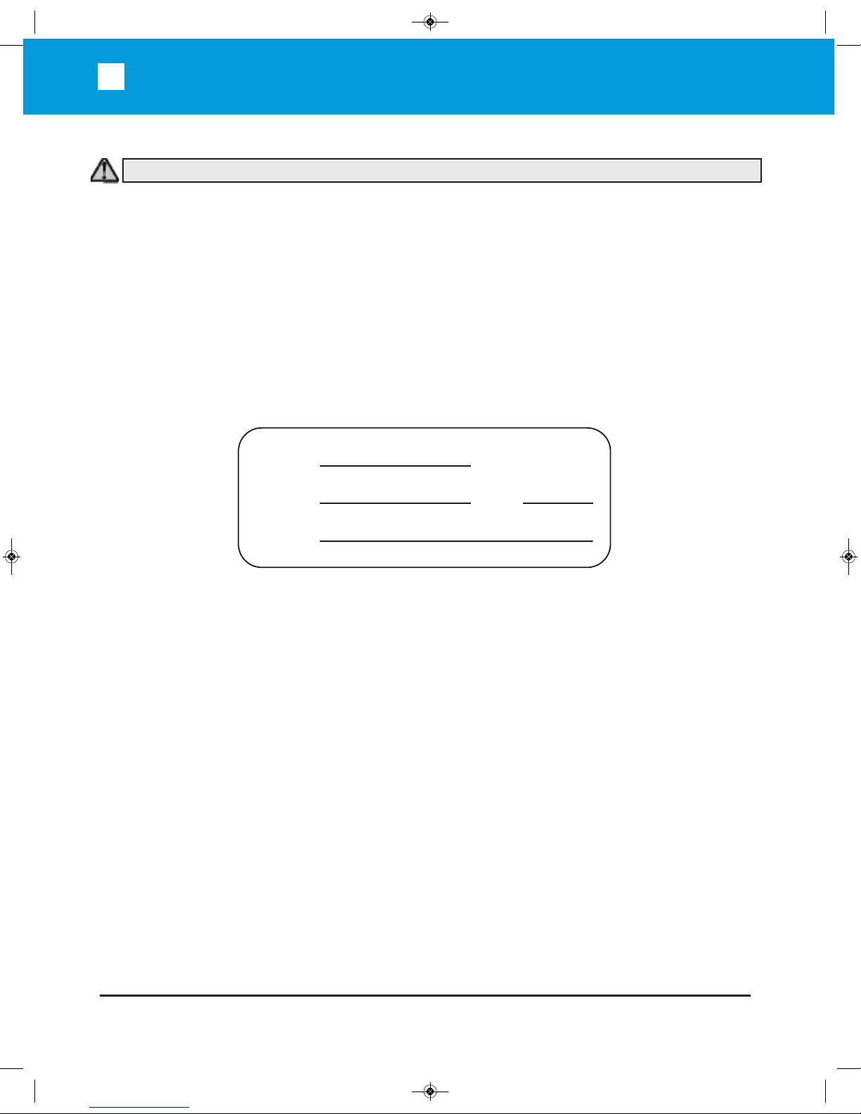
RESIDENTIAL VEHICULAR GATE OPERATOR
CLASS I – A vehicular gate operator (or system) intended for use In
a home of one-to four single family dwelling, or a garage or parking
area associated there with.
COMMERCIAL/GENERAL ACCESS VEHICULAR GATE OPERATOR
CLASS II – A vehicular gate operator (or system) intended for use in
a commercial location or building such as a multi-family housing unit
¿YHRUPRUHVLQJOHIDPLO\XQLWVKRWHOJDUDJHVUHWDLOVWRUHRURWKHU
building servicing the general public.
INDUSTRIAL/LIMITED ACCESS VEHICULAR GATE OPERATOR
CLASS III – A vehicular gate operator (or system) intended for use
in an industrial location or building such as a factory or loading dock
area or other locations not intended to service the general public.
RESTRICTED ACCESS VEHICULAR GATE OPERATOR
CLASS IV – A vehicular gate operator (or system) intended for use in
a guarded industrial location or building such as an air port security
area or other restricted access locations not servicing the general
public, in which unauthorized access is prevented via supervision by
security personnel.
HOTEL
FACT ORY
DOCK
HANGAR 00
WARNING – To reduce the risk of severe injury or death to person, please to follow these instructions:
BLSW1016 Manual_Layout 1 5/8/2015 5:06 PM Page 7
8
SAFETY INFORMATION
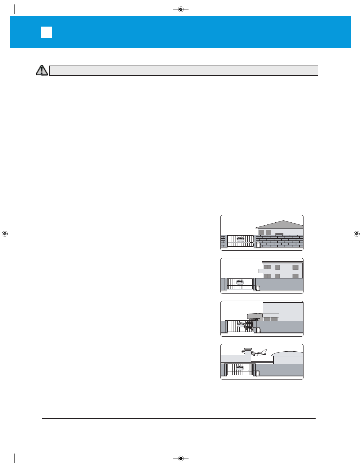
FOR USE WITH GATES OF A
MAXIMUM OF 16 FT IN LENGTH
AND 1000 LBS. IN WEIGHT
Specifications
This is NOT a pedestrian gate operator
Do NOT Install the gate operator to lift gates
Control Buttons Location:
1. Within sight of the gate,
2. At a minimum height of 5 feet so
small children are not able to
reach it, and make sure it is
away from all moving parts of
the gate.
1000 lb.
MAX.
16'-0"
CLOSE
STOP
OPEN
Location
of Control
Buttons
Location
of Control
Buttons
Maximum Gate Length:
Maximum Gate Weight:
Maximum Aperture Angle:
Power Requirements:
Operating Temperature:
16 feet
1000 lbs
120 deg.
120 VAC Single Phase at 2 Amps
or
220 VAC Single Phase at 1 Amp
-20°C (-4°F) to 70°C (158°F)
WARNING – To reduce the risk of severe injury or death to person, please to follow these instructions:
BLSW1016 Manual_Layout 1 5/8/2015 5:06 PM Page 8
9
INSTALLATION
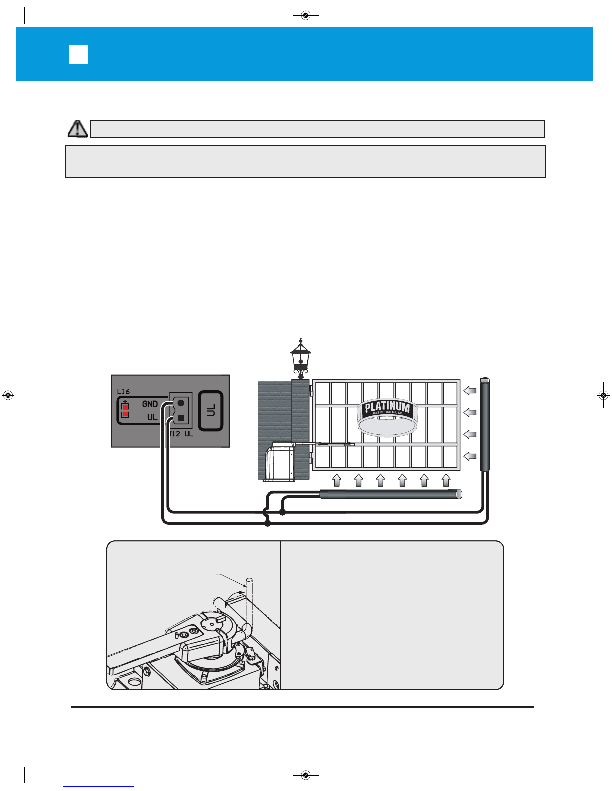
Contact Sensor (Edge) Installation:
Secondary Entrapment Protection
One or more contact sensors shall be located on the inside and outside leading edge of a swing gate.
Also if the bottom edge of a swing gate is more than 6” (152mm) above the ground at any point in its
travel on or more sensors shall be located to protect from the bottom edge.
A wireless contact sensor such as one that transmits radio frequency signals to the gate
operator for entrap-ment protection functions shall be located where the transmission of the
signals are not obstructed or im-peded by building structures, natural landscaping or similar
obstruction. A wireless contact sensor shall function under the intended end-use conditions.
A hardwired contact sensor shall be located and its wiring arranged so that the communica-
tion between the sensor and the gate operator is not subjected to mechanical damage.
Use only Miller Edge 3-sided activation type MGR20 or MDS20 to comply with UL325
3-Sided Edge Sensor
3-Sided Edge Sensor
When manual operation is required:
1. Remove the Hat
2. Lift the Locking Handle.
3. Remove the Clutch Key
To reengage the gate operator:
1. Align the Clutch and the notches on the
Output Shaft.
2. Insert the Clutch Key.
3. Push down the Locking Handle.
4. Reattach the Hat.
Attention: Lock and release operations MUST
be performed with motor NOT RUNNING.
Manual Release
Locking Handle
(in Unlocked
Position)
Note: This type of installation DOES NOT reverse the gate all the way back to its limits when the photobeam is obstructed. This installation is only to protect against entrapment and to comply with UL325.
WARNING – To reduce the risk of severe injury or death to person, please to follow these instructions:
BLSW1016 Manual_Layout 1 5/8/2015 5:06 PM Page 9
10
INSTALLATION
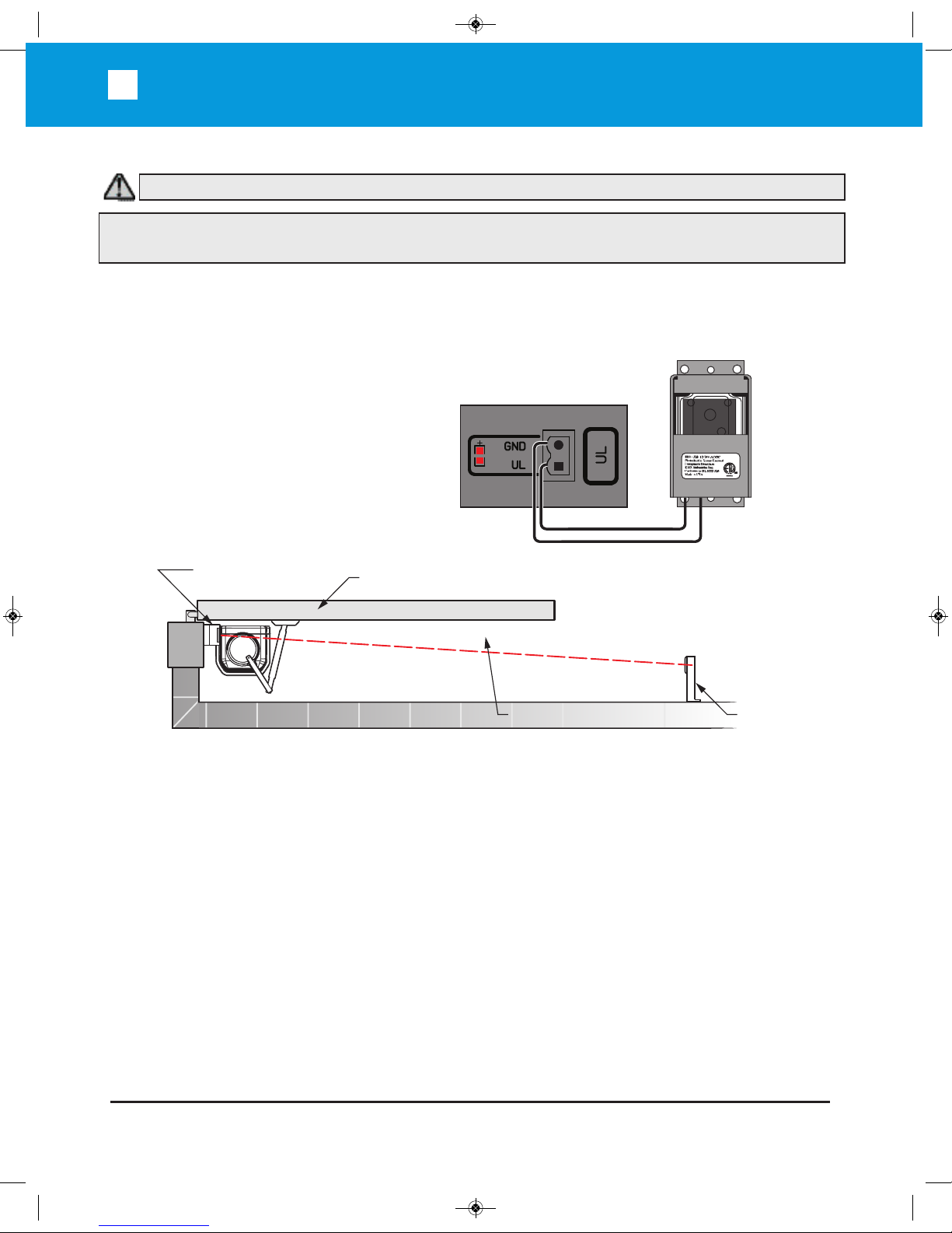
Non-Contact Sensors (Photoelectric Sensors) Installation:
One or more non-contact sensors shall be located where the risk of entrapment or obstruction exists,
such as the perimeter reachable by a moving gate or barrier.
Install photoelectric sensors to protect
against any entrapment or safety conditions
encountered in your gate application.
We recommend the use of EMX IRB-325
photoeyes to comply with UL325.
Open Position
Photo Beam Device
Reflector
Potential Entrapment Area
Consult the UL325 device installation manual for more detail information about the usage,
installation and maintenance of this device.
Note: This type of installation DOES NOT reverse the gate all the way back to its limits when the photobeam is obstructed. This installation is only to protect against entrapment and to comply with UL325.
TX
EMX Model
IRB-325
Shown
Connection ‘1’ (C1)
Connection ‘2’ (NC1)
WARNING – To reduce the risk of severe injury or death to person, please to follow these instructions:
BLSW1016 Manual_Layout 1 5/8/2015 5:06 PM Page 10

11
Installation: Inductive Loops
Inductive Loops Installation:
Safety loops allows the gate to stay open when vehicles are obstructing the gate path.
If the gate is longer than the vehicles that pass through it a center loop is recommended and should
be installed. A center loop prevents the gate from closing when a vehicle is between the safety loops.
Safety loops are required when using a center loop. See Loop Wiring.
Outside
Inside
Outside Safety
Loop
Center
Loop
Inside Safety
Loop
Exit
Loop
5'
5' 5'
XX
5'
Gate in Open Position
Even with Open Gate
Outside
Safety
Loop
Outside Inside
Center
Loop
Inside
Safety
Loop
Exit
Loop
Check with local regulations and accepted best practice requirements for every installation.
S
WARNING – Consult the installation instructions from the loop detector manufacturer. The following
statements are provided as a guide but different requirements may be required by the vehicular loop
detector manufacturer.
BLSW1016 Manual_Layout 1 5/8/2015 5:06 PM Page 11
12
Installation: inductive loops
WARNING – This product is an accessory or part of a system. Always read and follow the manufacturer’s instructions for the equipment before connecting this product. Comply with all applicable codes
and safety regulations. Failure to do so may result in damage, injury or death.
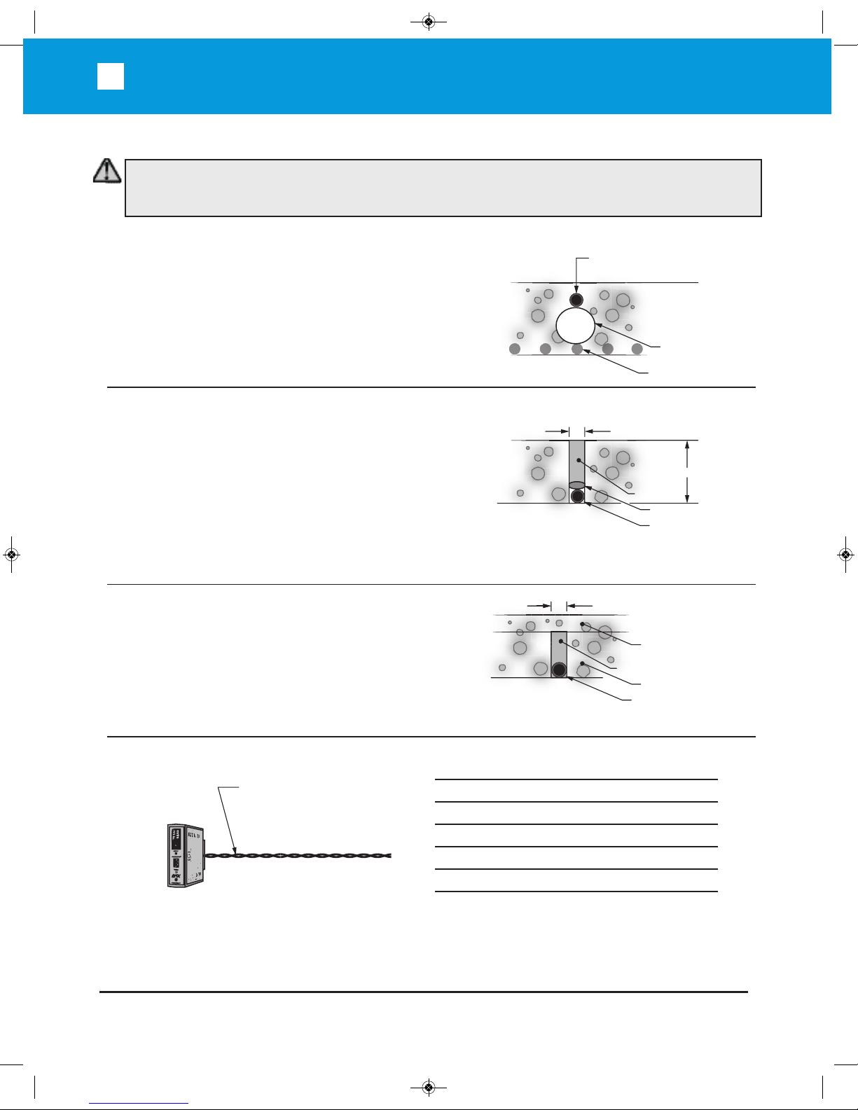
Inductive Loops Installation:
Recommended # of Turns
Perimeter in Feet # of Turns
10 5
20 4
30-40 3
50-100 2
General Installation Guidelines
Lead-in wire (wire from loop to
detector) must be must be twisted
a minimum of 6 turns/ foot to
avoid the effects of noise or other
interference.
Detection height is approximately 70%
of the shortest side of the loop.
1" Min.
Backer-Rod
Vehicular Loop
Detector Wire
Sealant
Saw Cut
Concrete Slab Cross View
1 - 1 1/4in. PVC Pipe
Steel Rebar
Concrete Slab Cross View
Vehicular Loop
Detector Wire
Existing Surface
Vehicular Loop
Detector Wire
Sand filled Saw Cut
Saw Cut
Asphalt Re-surface
New Asphalt
New Slab Pour
Ty-wrap 1 1/4” PVC Pipe to the top of the rebar in the
size and configuration of the loop (i.e. 4ft x 8ft). Then
ty-wrap the loop to the top of the PVC frame. This
stabilizes the loop during the pour and separates it
from the rebar.
Saw Cut Existing Surface
Cut “ deep into the existing surface, place a 45° cut
at the corners to prevent sharp edges from damaging
the loop wire. Notch out for the ”T” connection where
the lead wire connects to the loop. Remove all debris
from the finished cut with compressed air. Place the
loop into the saw cut. Place backer material into the
saw cut over the loop wire and pack tightly. Place a
high quality sealer over the saw cut to seal the
surface.
Resurface Asphalt
Saw cut the existing surface 3/4” deep and place a
45° cut at the corners to prevent sharp edges from
damaging the loop wire. Remove all debris from the
finished cut with compressed air. Place sand over the
loop wire to the surface and pack tightly. Lay new
asphalt.
BLSW1016 Manual_Layout 1 5/8/2015 5:06 PM Page 12
 Loading...