

Platinum Access Systems ACTP715 Installation Instruction And Owenrs Manual
ACTP715
ACTP715 Manual_Layout 1 11/4/2014 3:53 PM Page 1

TECHNICAL SUPPORT: (909) 259-6001
ACTP715
1
Installation Instructions & Safety Information Manual
ACTP715
Vehicular Gate Operator
Class I, Class II, Class III, and Class IV
TA BLE OF CONTENTS
Gate Operator Class Categories & Example
Protection Against Entrapment
Use & Application
Important Safety Instructions
Maintenance Instructions
Intended Use
Types of Installations
Mounting Instructions
Entrapment Protection
Inductive Loops
Alarm Reset Switch
Warning Placards
Electrical
Primary Unit
Primary/Secondary Connections
Loop Rack
Accessory Connections
Selectable Features
Solar Installation
Parts Diagram
....................................................2
....................................................3
....................................................4
....................................................5
....................................................6
....................................................7
.................................................8-9
.............................................10-12
..................................................13
.............................................14-15
..................................................16
.............................................17-19
..................................................20
..................................................21
..................................................22
.............................................23-26
.............................................27-28
..................................................29
..................................................30
ACTP715 Manual_Layout 1 11/4/2014 3:53 PM Page 3
2
TECHNICAL SUPPORT: (909) 259-6001
ACTP715
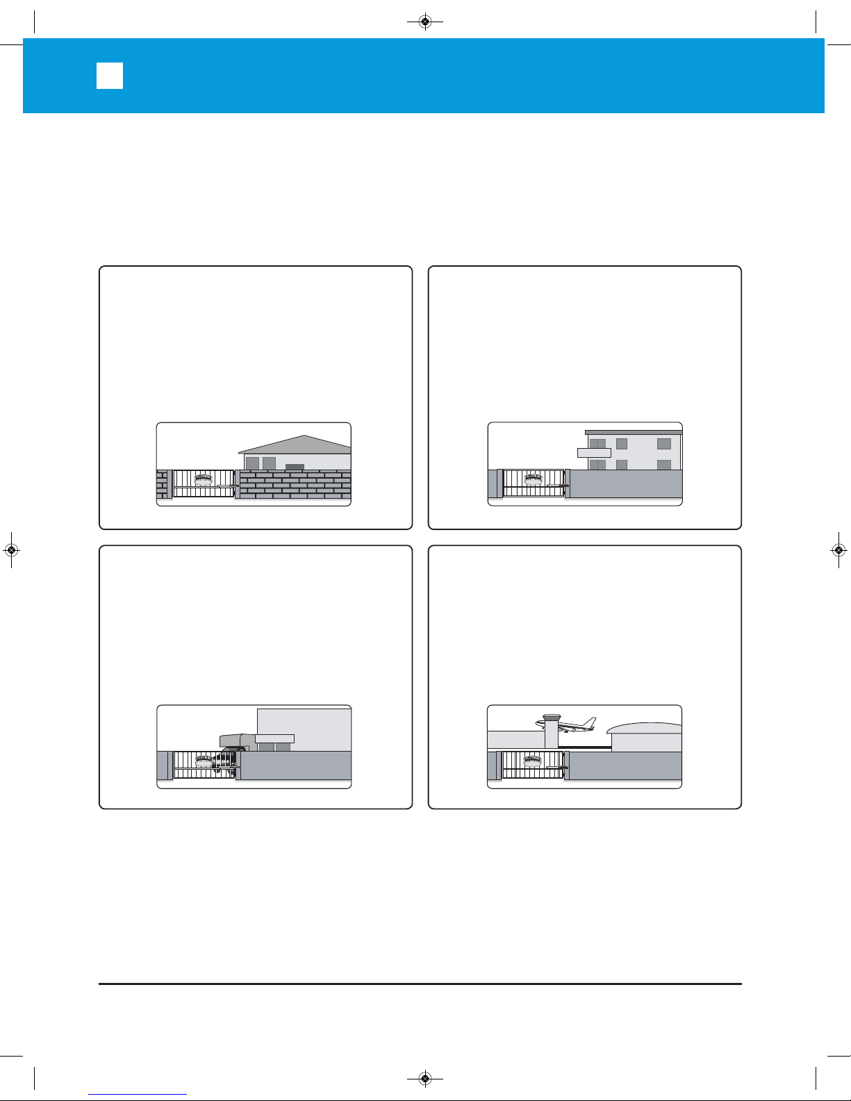
Gate operator class categories and examples
HOTEL
FACT ORY
DOCK
HANGAR 00
READ AND FOLLOW ALL INSTRUCTIONS MANUAL BEFORE ATTEMPTING
ANY INSTALLATION
Residential Vehicular Gate Operator
Class I
A vehicular gate operator (or system) intended
for use in a home of one-to four single family
dwelling, or a garage or parking area associated
therewith.
Commercial/General Access
Vehicular Gate Operator Class II
A vehicular gate operator (or system) intended
for use in a commercial location or building such
DVDPXOWLIDPLO\KRXVLQJXQLW¿YHRUPRUHVLQJOH
family units), hotel, garages, retail store, or other
building servicing the general public.
Industrial/Limited Access Vehicular
Gate Operator Class III
A vehicular gate operator (or system) intended for
use in an industrial location or building such as
a factory or loading dock area or other locations
not intended to service the general public.
Restricted Access Vehicular Gate
Operator Class IV
A vehicular gate operator (or system) intended
for use in a guarded industrial location or building
such as an airport security area or other restricted
access locations not servicing the general public,
in which unauthorized access is prevented via
supervision by security personnel.
ACTP715 Manual_Layout 1 11/4/2014 3:53 PM Page 4
TECHNICAL SUPPORT: (909) 259-6001
ACTP715
3
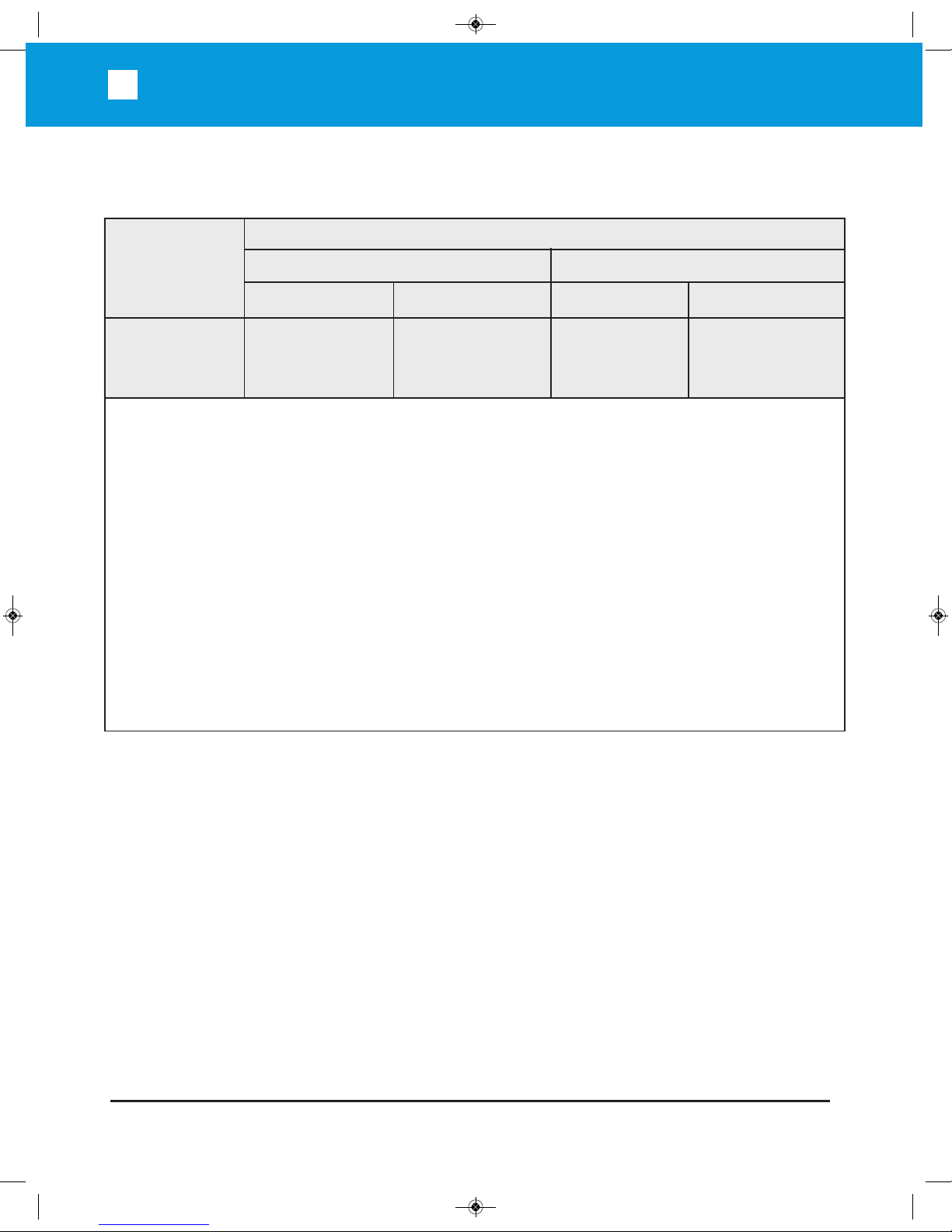
PROTECTION AGAINST ENTRAPMENT
Usage Class
Gate Operator Category
Horizontal Slide, Vertical lift, and Vertical Pivot
Swing and Vertical Barrier (arm)
Primary Type* Secondary Type* Primary Type* Secondary Type*
Vehicular I and II
Vehicular III
Vehicular IV
A
A, B1, or B2
A, B1, B2, or D
B1, B2, C, or D
A, B1, B2, C, D, or E
A, B1, B2, C, D, or E
B1, B2, or D
A, B1, B2, D, or E
A, B1, B2, D, or E
A, or C
A, B1, B2, or C
A, B1, B2, C, or D
Note - The same type of device shall not be utilized for both the primary and the secondary entrapment
protection means. Use of a single device to cover both the opening and closing directions is in accordance with
the requirement; however, a single device is not required to cover both directions. A combination of one Type
B1 for one direction and one Type B2 for the other direction is the equivalent of one device for the purpose of
complying with the requirements of either the primary or secondary entrapment protection areas.
a
Entrapment protection Types:
Type A: Inherent entrapment protection system.
Type B1: Provision for connection of, supplied with, a non-contact sensor (photoelectric sensor
or the equivalent).
Type B2: Provision for connection of, or supplied with, a contact sensor (edge device or the equivalent)
Type C: Inherent adjustable clutch or pressure relief device.
Type D: Provision for connection of, or supplied with, an actuating device requiring continuous pressure to
maintain opening or closing motion of the gate.
Type E: An audio alarm.
ACTP715 Manual_Layout 1 11/4/2014 3:53 PM Page 5

4
TECHNICAL SUPPORT: (909) 259-6001
ACTP715
Use and Application
The model ACTP715 is intended for Class I, II, III and IV usage on a vehicular slide gate
application.
a) Install the gate operator only when:
1) The operator is appropriate for the construction of the gate and the usage Class of the gate,
2) All openings of a horizontal slide gate are guarded or screened from the bottom of the gate to a minimum
of 4 feet (1.22 m) above the ground to prevent a 2-1/4 inch (57.2 mm) diameter sphere from passing
through the openings anywhere in the gate, and in that portion of the adjacent fence that the gate covers
in the open position,
3) All exposed pinch points are eliminated or guarded, and
4) Guarding is supplied for exposed rollers.
b) The operator is intended for installation only on gates used for vehicles. Pedestrians must be supplied with
a separate access opening. The pedestrian access opening shall be designed to promote pedestrian usage.
Locate the gate such that persons will not come in contact with the vehicular gate during the entire path of
travel of the vehicular gate.
c) The gate must be installed in a location so that enough clearance is supplied between the gate and adjacent
structures when opening and closing to reduce the risk of entrapment. Swinging gates shall not open into
public access areas.
d) The gate must be properly installed and work freely in both directions prior to the installation of the gate opera-
tor. Do not over-tighten the operator clutch or pressure relief valve to compensate for a damaged gate.
e) For gate operators utilizing Type D protection:
1) The gate operator controls must be placed so that the user has full view of the gate area when the gate is
moving,
2 The placard equivalent to the following: “To reduce the risk of electric shock the operator power is to be
provided from a weatherproof outlet in the case of attachment plug connection or weatherproof junction
box in the case of permanent wiring according to the National Electrical Code, NFPA 70.” shall be placed
adjacent to the controls,
3) An automatic closing device (such as a timer, loop sensor, or similar device) shall not be employed, and
4) No other activation device shall be connected.
ACTP715 Manual_Layout 1 11/4/2014 3:53 PM Page 6
TECHNICAL SUPPORT: (909) 259-6001
ACTP715
5
Important Safety Instructions
WARNING – To reduce the risk of injury or death:
1. READ AND FOLLOW ALL INSTRUCTIONS.
2. Never let children operate or play with gate controls. Keep the remote control away from children.
3. Always keep people and objects away from the gate. NO ONE SHOULD CROSS THE PATH OF THE
MOVING GATE.
4. Test the gate operator monthly. The gate MUST reverse on contact with a rigid object or stop when an object
activates the non-contact sensors. After adjusting the force or the limit of travel, retest the gate operator.
Failure to adjust and retest the gate operator properly can increase the risk of injury or death.
5. Use the emergency release only when the gate is not moving.
.((3*$7(63523(5/<0$,17$,1('5HDGWKHRZQHU¶VPDQXDO+DYHDTXDOL¿HGVHUYLFHSHUVRQPDNH
repairs to gate hardware.
7. The entrance is for vehicles only. Pedestrians must use separate entrance.
8. SAVE THESE INSTRUCTIONS
Maximum Gate Weight: 700 lbs.
Maximum Gate Length: 15 feet
Opening Time: 90° opening in 21-25 seconds
Maximum Opening Angle: 120°
Power Requirements: 120 VAC Single Phase at 2 Amps or 220 VAC Single Phase at 1 Amp
Main Power: Power Input: 100-240 VAC
Select 115 /230 VAC Single Phase
Built-in 24VDC battery backup (7AmpHr 12VDC x 2)
Operating Temperature: -20°C (-4°F) to 70°C (158°F)
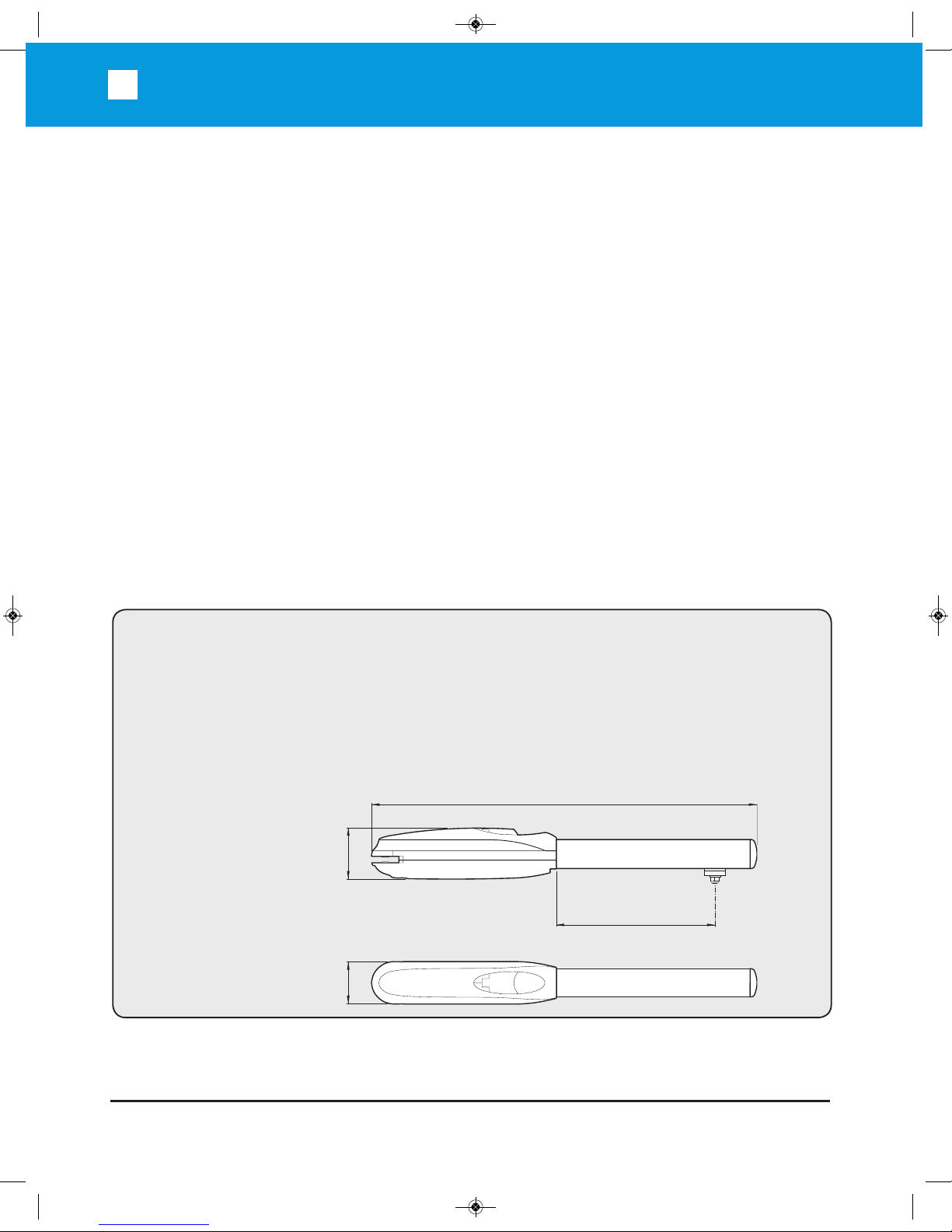
Arm Weight: 40 lbs.
Arm Dimensions:
SPECIFICATIONS
41 (1040 mm)
19 11/16 (500 mm)
(120 mm)
4
23
/
32
(100 mm)
3
15
/
16
ACTP715 Manual_Layout 1 11/4/2014 3:53 PM Page 7

6
TECHNICAL SUPPORT: (909) 259-6001
ACTP715
Maintenance Instructions
Maintenance instructions of ACTP715 performed by a qualified gate operator technician
Installation, all connections, programming, repair and modifications must be done by a
qualified professional gate operator installer.
Maintenance instructions of ACT715 performed by the end user/home owner
The following services need to be periodically performed:
• Check and adjust the gate operator for force, speed, and sensitivity.
• Make sure all power (AC/DC ) connections are corrosion free.
• Check all batteries for proper voltage of the intended use. A fully charged battery must be 26
VDC minimum.
&KHFNWKHLQFRPLQJOLQHYROWDJHDQGFRQ¿UPLWLVZLWKLQRILWVUDWLQJRUYROWV
• Verify battery backup functionally by turning off the power source (115 VAC and 230 VAC).
Don’t forget to restore power after testing.
• Check the wheels, guide rollers, chain, and lubricate where needed with a heavy-duty, highperformance
lubricant and avoid spillage.
• Inspect the track for any signs of cracking or separation.
• Test (use caution) all contact and non-contact sensors, all vehicle detectors, keypad, telephone
entry system or other control devices applicable.
• Test the manual release feature on the operator.
,QVWDOODWLRQDOOFRQQHFWLRQVSURJUDPPLQJUHSDLUDQGPRGL¿FDWLRQVPXVWEHGRQHE\DTXDOL¿HGSURIHVVLRQDO
JDWHRSHUDWRULQVWDOOHU(QGXVHUVKRPHRZQHUVPXVWFDOODTXDOL¿HGSURIHVVLRQDOJDWHRSHUDWRULQVWDOOHUIRU
SURJUDPPLQJFKDQJHVUHSDLUVDQGPRGL¿FDWLRQV
Although all Platinum Access Systems’ gate operators are virtually maintenance free to an end user/home ow
minimal maintenance is recommended to ensure a smooth operation of this unit.
End users/home owners:
• Perform maintenance every six months, or when strenuous noise from wheels and/or guide rollers is
detected. Lubricate them with heavy-duty, high-performance lubricant and avoid spillage.
• DO NOT take the cover off the operator and/or the electrical control box to perform maintenance.
• Make sure there are no cars in the path of the gate while performing maintenance.
• Make sure the person performing maintenance is the only person in control of all control devices
in order to avoid possible involuntary activation of the gate operator.
• Keep spraying water hoses and sprinkler systems away from the gate, gate operator and the
electrical control box at all times. Keep that general area as clean as humanly possible.
• Test (use caution) all non-contact sensors, all vehicle detectors, keypad, telephone entry system or
ACTP715 Manual_Layout 1 11/4/2014 3:53 PM Page 8
TECHNICAL SUPPORT: (909) 259-6001
ACTP715
7
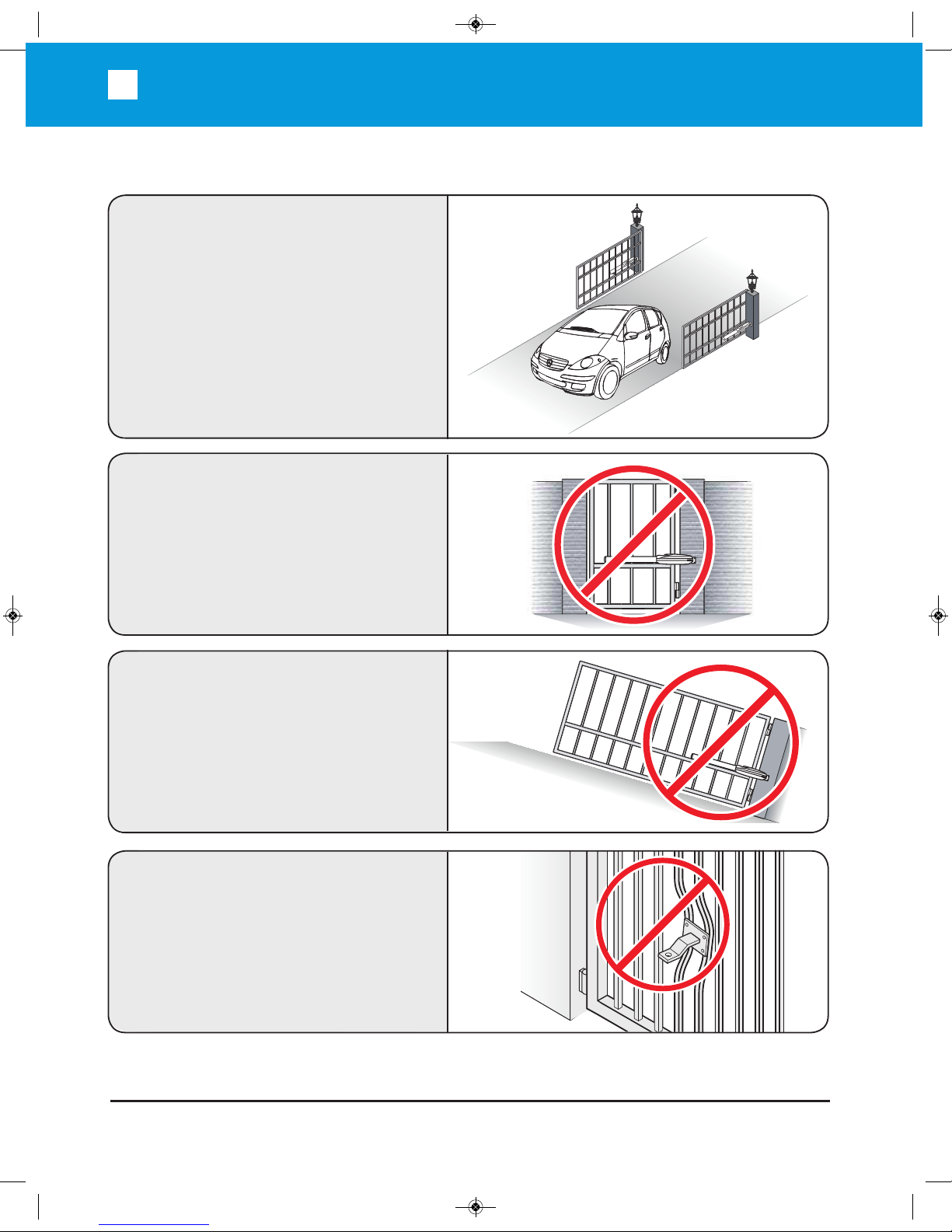
Intended Use
Do not attach/weld the front bracket
plate to pickets directly.
The operator is intended for
installation on a vehicular
swing gate only.
The operator IS NOT intended to be
used for any pedestrian gate.
The operator IS NOT intended to be
used for any uphill gate.
ACTP715 Manual_Layout 1 11/4/2014 3:53 PM Page 9
8
TECHNICAL SUPPORT: (909) 259-6001
ACTP715
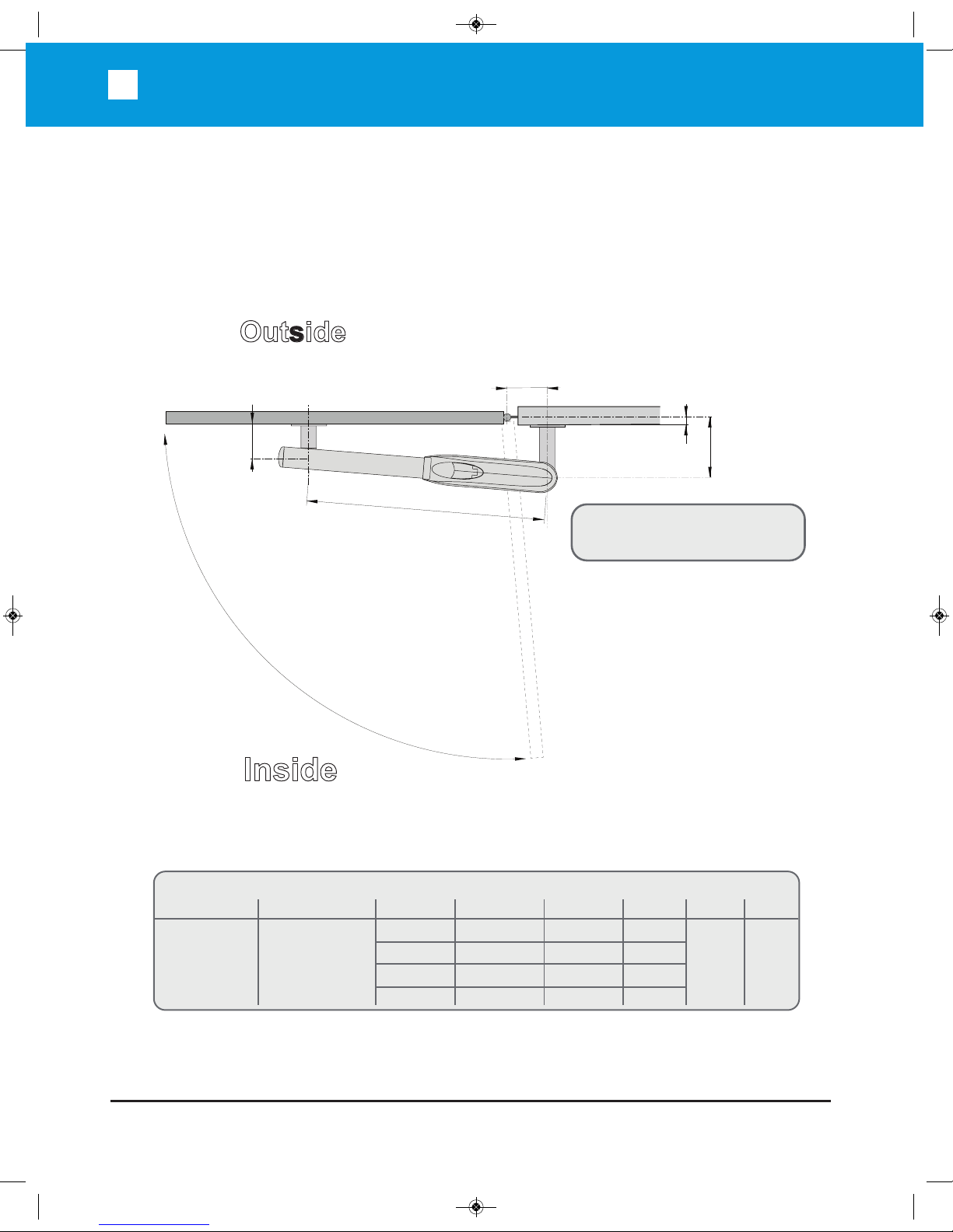
Types of Installations
OPEN INSIDE INSTALLATION IN inches (mm)
A*
Min 5
1
/8”(130)
Max 7
7
/8” (200)
B*
Min 6
11
/16” (170)
Max 11
7
/16” (290)
A
6
11
/16” (170)
7
7
/8” (200)
7
7
/8” (200)
5
1
/8” (130)
B
6
11
/16” (170)
7
7
/8” (200)
6
11
/16” (170)
11
7
/16” (290)
C
3
15
/16” (100)
5
1
/8” (130)
3
15
/16” (100)
8
5
/8” (220)
D
90°
95°
120°
90°
E
4
23
/32”
(120)
F
35 13/16”
(910)
*Use measurements between minimum and maximum.
A
E
F
B
C
D:
90°/120° Travel time: 21 to 25 sec
Inside
Outside
To obtain desired dimension B,
cut the Back Mounting Bracket.
OPEN INSIDE INSTALLATION:
ACTP715 Manual_Layout 1 11/4/2014 3:53 PM Page 10
TECHNICAL SUPPORT: (909) 259-6001
ACTP715
9
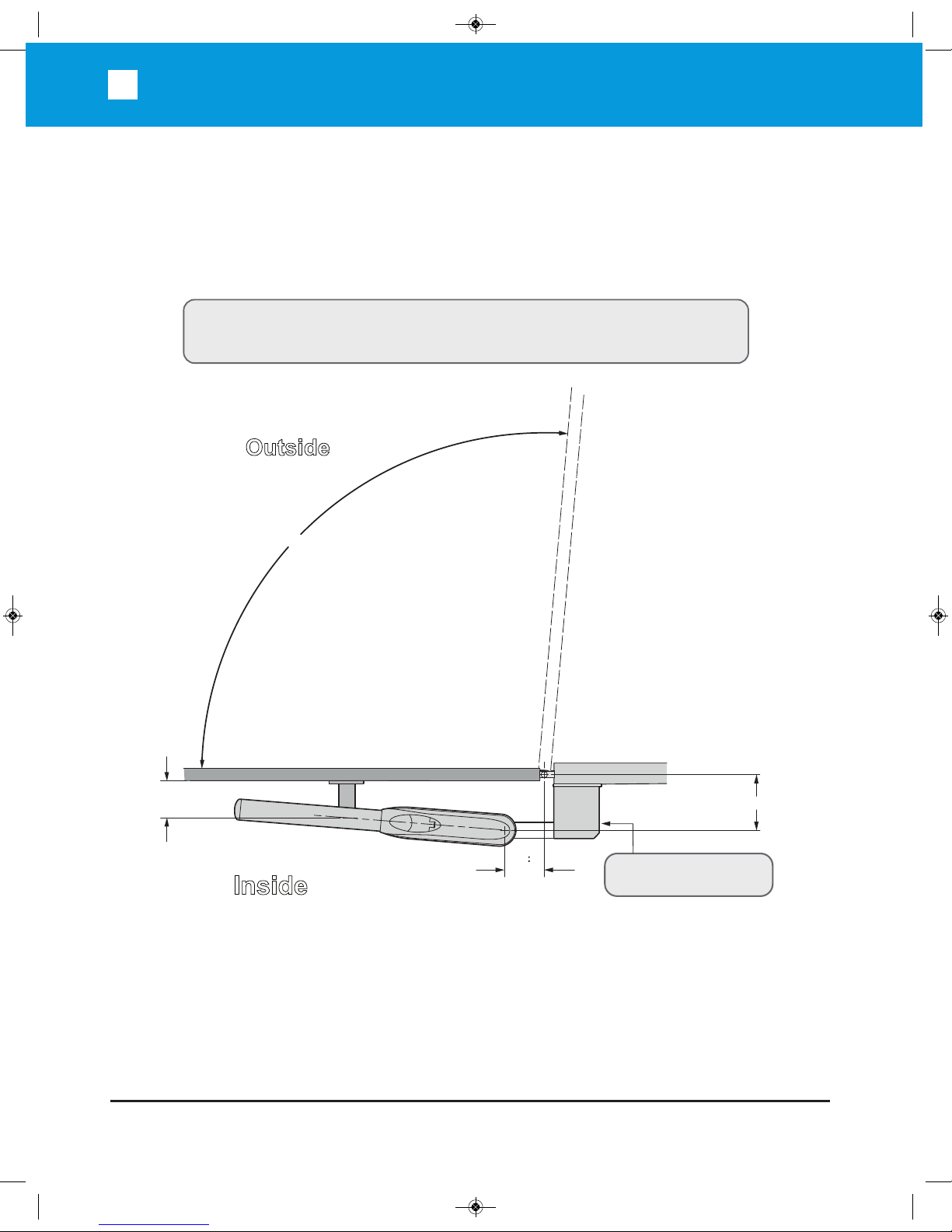
Types of Installations
Inside
Outside
Additional bracket
required (not supplied)
A: 7 ⅞"
D: 90°/105° Travel time: 21 to 24 sec
B
6 ⅝"
C: 4 ¾"
Don’t install the Swing gate
to open into public access areas.
To reduce the risk of entrapment leave enough clearance in between the gate and
adjacent structures during opening.
OPEN OUTSIDE INSTALLATION:
ACTP715 Manual_Layout 1 11/4/2014 3:53 PM Page 11
 Loading...