

Page 1

Platinum Z5 CD™
FM Transmitter Manual
Platinum Z5CD™
FM Transmitter Manual
888-2408-002
June 9, 2003
Rev C.
T.M. No. 888-2408-002
© Copyright Harris Corporation 2000, 2001
All rights reserved
Page 2

888-2408-002
WARNING: Disconnect primary power prior to servicing.
Returns And Exchanges
Damaged or undamaged equipment should not be returned unless written approval and a
Return Authorization is received from HARRIS CORPORATION, Broadcast Systems
Division. Special shi pping instructions an d coding will be provided to assure proper
handling. Complete details regarding circumstances and reasons for return are to be
included in the request for ret urn. Custom equipment or specia l order equipment is not
returnable. In those instances where return or exchange of equipment is at the request of the
customer, or convenience of the customer, a restocking fee will be charged. All returns will
be sent freight prepaid and properly insured by the customer. When communicating with
HARRIS CORPORATION, Broadcast Division, specify the HARRIS Order Number or
Invoice Number.
Unpacking
Carefully unpack the equipment and preform a visual inspection to determine that no
apparent damage was incurred during shipment. Retain the shipping materials un til it has
been determined that all received equipment is not damaged. Locate and retain all
PACKING CHECK LISTs. Use the PACKING CHECK LIST to help locate and identify
any components or assemblies which are removed for shipping and must be reinstalled.
Also remove any shipping supports, straps, and packing materials prior to initial turn on.
Technical Assistance
HARRIS Tech nical and Trouble shooting assist ance is availabl e from HARRIS Fiel d
Service during norm al business hours (8 :00 AM - 5:00 PM Centra l Time). Emergency
service is available 24 hours a day. Telephone 217/222-8200 to contact the Field Service
Department or address correspondence to Field Service Department, HARRIS CORPORATION, Broadcast Systems Division, P.O. Box 4290, Quincy, Illinois 62305-4290,
USA. The HARRIS factory may also be contacted through a FAX facility (217/222-7041)
or a TELEX service (650/372-2976).
Replaceable Parts Service
Replacement parts are available 24 hours a day, seven days a week from the HARRIS
Service Parts Department. Telep hone 217/222-82 00 to contact the service part s department
or address correspondence to Service Parts Department, HARRIS CORPORATION,
Broadcast Systems Division, P.O. Box 4290, Quincy, Illinois 62305-4290, USA. The
HARRIS factory may also be contacted through a FAX facility (217/222-7041) or a
TELEX service (650/372-2976).
NOTE
The # symbol used in the parts list means used with (e.g. #C001 =
used with C001)
Page 3

2408ti.fm
888-2408-002
WARNING: Disconnect primary power prior to servicing.
MANUAL REVISION HISTORY
Platinum Z5 CD™
888-2408-002
Rev. Date ECN Pages Affected
B 12-17-01 47926 Title page, added MRH1/MRH2, sections 2 and 4.
C 06-09-03 TBD Title page, MRH1/MRH2, and page 2-28.
Page 4

888-2408-002
WARNING: Disconnect primary power prior to servicing.
Page 5
2408ti.fm
888-2408-002
WARNING: Disconnect primary power prior to servicing.
Guide to Using Harris Parts List Information
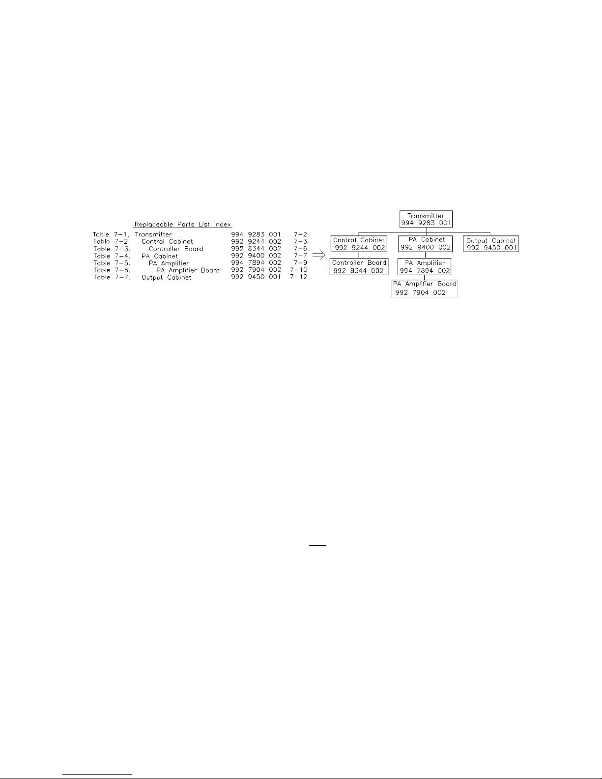
The Harris Replaceable Parts List Index portrays a tree structure with the major items being leftmost in the index.
The example below shows the Transmitter as the highest item in the tree structure. If you were to look at the bill of
materials table for the Transmitter you would find the Control Cabinet, the PA Cabinet, and the Output Cabinet. In
the Replaceable Parts List Index the Control Cabinet, PA Cabinet, and Output Cabinet show up one indentation level
below the Transmitter and implies that they are used in the Transmitter. The Controller Board is indented one level
below the Control Cabinet so it will show up in the bill of material for the Control Cabinet. The tree structure of this
same index is shown to the right of the table and shows indentation level versus tree structure level.
Example of Replaceable Parts List Index and equivalent tree structure:
The part number of the item is shown to the right of the description as is the page in the manual where the bill for
that part number starts.
Inside the actual tables, four main headings are used:
Table #-#. ITEM NAME - HARRIS PART NUMBER - this line gives the information that corresponds to the
Replaceable Parts List Index entry;
HARRIS P/N column gives the ten digit Harris part number (usually in ascending order);
DESCRIPTION column gives a 25 character or less description of the part number;
REF. SYMBOLS/EXPLANATIONS column 1) gives the reference designators for the item (i.e., C001, R102,
etc.) that corresponds to the number found in the schematics (C001 in a bill of material is equivalent to C1 on the
schematic) or 2) gives added information or further explanation (i.e., “Used for 208V operation only,” or “Used
for HT 10LS only,” etc.).
Inside the individual tables some standard conventions are used:
A # symbol in front of a component such as #C001 under the REF. SYMBOLS/EXPLANATIONS column means
that this item is used on or with C001 and is not the actual part number for C001.
In the ten digit part numbers, if the last three numbers are 000, the item is a part that Harris has purchased and
has not manufactured or modified. If the last three numbers are other than 000, the item is either manufactured by
Harris or is purchased from a vendor and modified for use in the Harris product.
The first three digits of the ten digit part number tell which family the part number belongs to - for example, all
electrolytic (can) capacitors will be in the same family
(524 xxxx 000). If an electrolytic (can) capacitor is found
to have a 9xx xxxx xxx part number (a number outside of the normal family of numbers), it has probably been
modified in some manner at the Harris factory and will therefore show up farther down into the individual parts
list (because each table is normally sorted in ascending order). Most Harris made or modified assemblies will
have 9xx xxxx xxx numbers associated with them.
The term “SEE HIGHER LEVEL BILL” in the description column implies that the reference designated part
number will show up in a bill that is higher in the tree structure. This is often the case for components that may
be frequency determinant or voltage determinant and are called out in a higher level bill structure that is more
customer dependent than the bill at a lower level.
Page 6
888-2408-002
WARNING: Disconnect primary power prior to servicing.
Page 7

2408ti.fm
888-2408-002
WARNING: Disconnect primary power prior to servicing.
WARNING
The currents and voltages in this equipment are dangerous. Personnel must at all times observe safety warn ings, in struct ions and regu lations.
This manual is intended as a general guide for trained and qualified per sonnel who are
aware of the dangers inherent in handling potentially hazardous electrical/electronic
circuits. It is not intended to contain a complete statement of all safety precautions which
should be observed by personnel in using this or other electronic equipment.
The installation, operation, maintenance and service of this equipment involves risks both
to personnel and equipment, an d must be pe rformed only by qualified pe rsonnel exercis ing
due care. HARRIS CORPORATION shall not be responsible for injury or damage
resulting from improper procedures or from the use of improperly trained or inexperienced
personnel performing such tasks.
During installation and operation of this equipment, local building codes and fire protection standards must be observed. The following National Fire Prote ction Association
(NFPA) standards are recommended as reference:
• Automatic Fire Detectors, No. 72E
• Installation, Maintenance, and Use of Portable Fire Extinguishers, No. 10
• Halogenated Fire Extinguishing Agent Systems, No. 12A
WARNING
Always disconnect power before opening covers, doors, enclosures,
gates, panels or shields. Always use grounding sticks and short out
high volta ge points before servi cing. Never make int ernal adjustments, perform maintenance or service when alone or when fatigued.
Do not remove, short-circuit or tamper with interlock switche s on access covers, doors,
enclosures, gates, panels or shields. Keep away from live circuits, know your equipment
and don’t take chances.
WARNING
In case of emergency ensure that power has been disconnected.
If oil filled or electrolytic capacitors are utilized in your equipment, an d if a leak or b ulge
is apparent on the capacitor case when the unit is opened for service or mainten ance, allow
the unit to cool down before attempting to remove the defective capacitor. Do not attempt
to service a defective capacitor while it is hot due to the po ssibility of a case rup ture and
subsequent injury.
Page 8
888-2408-002
WARNING: Disconnect primary power prior to servicing.
Page 9

2408ti.fm
888-2408-002
WARNING: Disconnect primary power prior to servicing.
FIRST -AID
Personnel engaged in the installation, operation, maintenance or servicing of this
equipment are urged to become familiar with first-aid theory and practices. The following
information is not intended to be complete first-aid procedures, it is a brief and is only to
be used as a reference. It is the duty of all personnel using the equipment to be prepared to
give adequate Emergency First Aid and thereby prevent avoidable loss of life.
Treatment of Electrical Burns
1. Extensive burned and broken skin
A. Cover area with clean sheet or cloth. (Cleanest available cloth article.)
B. Do not break blisters, remove tissue, remove adhered particles of clothing, or
apply any salve or ointment.
C. Treat victim for shock as required.
D. Arrange transportation to a hospital as quickly as possible.
E. If arms or legs are affected keep them elevated.
NOTE
If medical help will not be available within an hour and the victim
is conscious and not vomiting, give him a weak solution of salt and
soda: 1 level teaspoonful of s al t and 1/ 2 le vel teas po onf ul of bak ing
soda to each quart of water (neither hot or co ld). Allow victim to si p
slowly about 4 ounces (a half of glass) over a period of 15 minutes.
Discontinue fluid if vomiting occurs. (Do not give alcohol.)
2. Less severe burns - (1st & 2nd degree)
A. Apply cool (not ice cold) compresses using the cleanest available cloth arti-
cle.
B. Do not break blisters, remove tissue, remove adhered particles of clothing, or
apply salve or ointment.
C. Apply clean dry dressing if necessary.
D. Treat victim for shock as required.
E. Arrange transportation to a hospital as quickly as possible.
F. If arms or legs are affected keep them elevated.
REFERENCE
ILLINOIS HEART ASSOCIATION
AMERICAN RED CROSS STANDARD FIRST AID AND PERSONAL SAFETY
MANUAL (SECOND EDITION)
Page 10

888-2408-002
WARNING: Disconnect primary power prior to servicing.
Page 11

888-2408-002 1
WARNING: Disconnect primary power prior to servicing.
Table of Contents
1 Introduction/Specifications
Introduction . . . . . . . . . . . . . . . . . . . . . . . . . . . . . . . . .1-1
Features/Benefits. . . . . . . . . . . . . . . . . . . . . . . . . . . . .1-2
General Description. . . . . . . . . . . . . . . . . . . . . . . . . . .1-3
Harris DIGIT Digital FM Exciter. . . . . . . . . . . . . . .1-3
Harris SuperCiter Analog Exciter. . . . . . . . . . . . . . .1-3
Redundant Exciters. . . . . . . . . . . . . . . . . . . . . . . . . .1-3
PA/IPA Modules . . . . . . . . . . . . . . . . . . . . . . . . . . . .1-4
RF Combining. . . . . . . . . . . . . . . . . . . . . . . . . . . . . .1-4
Control System . . . . . . . . . . . . . . . . . . . . . . . . . . . . .1-4
Directional RF Sample Port . . . . . . . . . . . . . . . . . . .1-5
Power Supplies . . . . . . . . . . . . . . . . . . . . . . . . . . . . .1-5
Air System . . . . . . . . . . . . . . . . . . . . . . . . . . . . . . . .1 -5
Performance Specifications. . . . . . . . . . . . . . . . . . . . .1-5
2 Installation & Initial Turn-On
Introduction . . . . . . . . . . . . . . . . . . . . . . . . . . . . . . . . .2-1
Unpacking . . . . . . . . . . . . . . . . . . . . . . . . . . . . . . . . . .2-1
Returns and Exchanges . . . . . . . . . . . . . . . . . . . . . . . .2-1
Air Cooling Requirements. . . . . . . . . . . . . . . . . . . . . .2-2
Z5 Transmitter Installation . . . . . . . . . . . . . . . . . . . . .2-2
Transmitter Placement . . . . . . . . . . . . . . . . . . . . . . .2-3
Removal of Pallet Bolts . . . . . . . . . . . . . . . . . . . . .2-3
Visual Inspection. . . . . . . . . . . . . . . . . . . . . . . . . . . .2-3
Exciter Installation . . . . . . . . . . . . . . . . . . . . . . . . . .2-4
3-Phase Power Supply Installation . . . . . . . . . . . . . .2-5
Power Transformer Tapping. . . . . . . . . . . . . . . . . .2-5
Power Supply Connections . . . . . . . . . . . . . . . . . .2-6
Single Phase Power Supply Installation . . . . . . . . . .2-8
Power Transformer Tapping. . . . . . . . . . . . . . . . . .2-8
Single Phase Power Supply Connections. . . . . . . .2-9
Transmitter AC Connections. . . . . . . . . . . . . . . . . . 2-11
Information concerning some 360 to 416 volt
systems . . . . . . . . . . . . . . . . . . . . . . . . . . . . . . . .2-11
AC Input Connection . . . . . . . . . . . . . . . . . . . . . .2-12
Grounding. . . . . . . . . . . . . . . . . . . . . . . . . . . . . . .2-13
Low Voltage Power Supply and Blower . . . . . . .2-14
Exciter AC Voltage Selection. . . . . . . . . . . . . . . .2-14
RF Output Connection . . . . . . . . . . . . . . . . . . . . . .2-14
Audio Input Connections . . . . . . . . . . . . . . . . . . . .2-14
External and Failsafe Interlock Connections . . . . . 2-15
External Interlock Connection . . . . . . . . . . . . . . .2-15
Failsafe Interlock Connection . . . . . . . . . . . . . . .2-15
Initial Turn-on. . . . . . . . . . . . . . . . . . . . . . . . . . . . .2-16
Remote Control Connections . . . . . . . . . . . . . . . . . 2-21
Control Inputs . . . . . . . . . . . . . . . . . . . . . . . . . . . 2-22
Status Ouputs. . . . . . . . . . . . . . . . . . . . . . . . . . . . 2-22
UPS IN/Remote Exciter S elect,
Configurable Input TB1-9. . . . . . . . . . . . . . . . . . . . 2-24
Using an Uninterruptable Power Supply or UPS. . 2-25
Setting The UPS Power Level. . . . . . . . . . . . . . . 2-25
Optimizing Efficiency. . . . . . . . . . . . . . . . . . . . . . . . 2-26
Setting the Low Power Alarm. . . . . . . . . . . . . . . . . . 2-27
Jumper Settings for In stallation of a Harris Exciter . 2-27
Power Distribution for Optimum Transmitter
Performance. . . . . . . . . . . . . . . . . . . . . . . . . . . . . . . 2-31
Overheating from Line Unbalance. . . . . . . . . . . . . 2-31
Transmitter Noise Performance . . . . . . . . . . . . . . . 2-31
The Causes of Line Unbalance. . . . . . . . . . . . . . . . 2-31
Three Phase Delta Distribution Transformers . . . . 2-32
Three Phase Wye Distribution Transformers . . . . . 2-33
3 Operator Guide
Introduction. . . . . . . . . . . . . . . . . . . . . . . . . . . . . . . . . 3-1
Transmitter Controls . . . . . . . . . . . . . . . . . . . . . . . . . . 3-2
Transmitter Metering. . . . . . . . . . . . . . . . . . . . . . . . . . 3-3
Forward Power (FWD PWR) Units of Measure . . . 3-3
Reflected Power (RFL PWR) Units of Measure . . . 3-3
Using the Diagnostic Display . . . . . . . . . . . . . . . . . . . 3-4
HOME . . . . . . . . . . . . . . . . . . . . . . . . . . . . . . . . . . . 3-5
BACK. . . . . . . . . . . . . . . . . . . . . . . . . . . . . . . . . . . . 3-6
MORE. . . . . . . . . . . . . . . . . . . . . . . . . . . . . . . . . . . . 3-6
Diagnostic Codes . . . . . . . . . . . . . . . . . . . . . . . . . . . 3-6
Asterisk and Pound Signs(*, #) . . . . . . . . . . . . . . . . 3-8
Fault Logging. . . . . . . . . . . . . . . . . . . . . . . . . . . . . . 3-8
Emergency Operating Procedures. . . . . . . . . . . . . . . . 3-9
Multiple PA Failures in a Foursome. . . . . . . . . . . . . 3-9
Manual Exciter Switching. . . . . . . . . . . . . . . . . . . . . 3-10
Manual IPA Switching . . . . . . . . . . . . . . . . . . . . . . . 3-10
Optimizing Efficiency. . . . . . . . . . . . . . . . . . . . . . . . 3-11
Fan Speed . . . . . . . . . . . . . . . . . . . . . . . . . . . . . . . . . 3-12
4 Overall System Theory
Introduction. . . . . . . . . . . . . . . . . . . . . . . . . . . . . . . . . 4-1
RF Flow Block Diagram Description. . . . . . . . . . . . . 4-1
Exciters. . . . . . . . . . . . . . . . . . . . . . . . . . . . . . . . . . . 4-1
IPAs . . . . . . . . . . . . . . . . . . . . . . . . . . . . . . . . . . . . . 4-3
PA . . . . . . . . . . . . . . . . . . . . . . . . . . . . . . . . . . . . . . . 4-3
Z-Plane Divider Board. . . . . . . . . . . . . . . . . . . . . . 4-3
Page 12

2 888-2408-002
WARNING: Disconn ect primary power pri or to servicing.
Table of Contents
Z-Plane Combiner Board . . . . . . . . . . . . . . . . . . . .4-3
5kW Hybrid Combiner . . . . . . . . . . . . . . . . . . . . . . .4-4
Detailed RF Theory of Operation . . . . . . . . . . . . . . . .4-4
Exciter Operation . . . . . . . . . . . . . . . . . . . . . . . . . . .4-4
Automatic Exciter Switching . . . . . . . . . . . . . . . . .4-4
Manual Exciter Switching . . . . . . . . . . . . . . . . . . .4-4
IPA. . . . . . . . . . . . . . . . . . . . . . . . . . . . . . . . . . . . . . .4-5
IPA Power Output. . . . . . . . . . . . . . . . . . . . . . . . . .4-5
IPA Power Supply. . . . . . . . . . . . . . . . . . . . . . . . . .4-5
IPA Backplane Board . . . . . . . . . . . . . . . . . . . . . . . .4-5
Main/Alternate Exciter Switching . . . . . . . . . . . . .4-6
Main/Alternate IPA Switching . . . . . . . . . . . . . . . .4-7
IPA Monitoring . . . . . . . . . . . . . . . . . . . . . . . . . . . .4-7
Air Flow Sensing.. . . . . . . . . . . . . . . . . . . . . . . . . .4-8
IPA_AB1 and IPA_AB2 interlocking. . . . . . . . . . .4-8
IPA Power Divider (3dB Hybrid). . . . . . . . . . . . . .4-8
Z-Plane Combiner/Divider Boards . . . . . . . . . . . . . .4-8
8-Way Divider . . . . . . . . . . . . . . . . . . . . . . . . . . . .4-9
8-Way Combiner. . . . . . . . . . . . . . . . . . . . . . . . . . .4-9
PA Modules . . . . . . . . . . . . . . . . . . . . . . . . . . . . .4-10
Power Amplifier (PA). . . . . . . . . . . . . . . . . . . . . .4-10
3 dB Hybrid Combiner. . . . . . . . . . . . . . . . . . . . .4-13
Harmonic Filter. . . . . . . . . . . . . . . . . . . . . . . . . . . . 4 -14
Directional Coupler Assembly . . . . . . . . . . . . . . . .4-14
Power Supply Block Diagram Description . . . . . . . .4-15
PA Power Supply. . . . . . . . . . . . . . . . . . . . . . . . . . .4-15
3-Phase Power Supply . . . . . . . . . . . . . . . . . . . . .4-15
Single Phase Power Supply . . . . . . . . . . . . . . . . .4-18
Low Voltage Power Supply. . . . . . . . . . . . . . . . . . .4-20
Detailed Power Supply Descriptions. . . . . . . . . . . . .4-20
3-Phase PA Power Supply. . . . . . . . . . . . . . . . . . . .4-20
Rectifier Board . . . . . . . . . . . . . . . . . . . . . . . . . . .4-22
Rectifier Board Circuit Description . . . . . . . . . . .4-22
Single Phase PA Power Supply. . . . . . . . . . . . . . . .4-25
Rectifier Board . . . . . . . . . . . . . . . . . . . . . . . . . . .4-25
Rectifier Board Circuit Description . . . . . . . . . . .4-26
Power Supply ID Jumpers. . . . . . . . . . . . . . . . . . . .4-28
Low Voltage Power Supply Board . . . . . . . . . . . . .4-28
Relays . . . . . . . . . . . . . . . . . . . . . . . . . . . . . . . . . .4-29
Cooling System Description . . . . . . . . . . . . . . . . . . .4-29
Control System Description. . . . . . . . . . . . . . . . . . . .4-30
Master Controller . . . . . . . . . . . . . . . . . . . . . . . . . .4-31
EEPROM U39 . . . . . . . . . . . . . . . . . . . . . . . . . . .4-31
APC, Automatic Power Control. . . . . . . . . . . . . .4-32
Calibration Factors and A/D Values . . . . . . . . . . . .4-34
DAC_APC_REF. . . . . . . . . . . . . . . . . . . . . . . . . .4-35
Forward Factor and A/D_FWD_PWR. . . . . . . . .4-36
APC Factor. . . . . . . . . . . . . . . . . . . . . . . . . . . . . .4-37
MAX HIGH, MAX LOW and UPS Power Levels4-37
EXC Factor and IPA Factor . . . . . . . . . . . . . . . . . 4-39
Reflect Factor and A/D_RFL_PWR . . . . . . . . . . 4-39
VSWR Foldback. . . . . . . . . . . . . . . . . . . . . . . . . . . 4-40
Master Controller Faults . . . . . . . . . . . . . . . . . . . 4-41
PA Controller Boards . . . . . . . . . . . . . . . . . . . . . . . 4-42
PA Turn On/Turn Off. . . . . . . . . . . . . . . . . . . . . . 4-42
Metering. . . . . . . . . . . . . . . . . . . . . . . . . . . . . . . . 4-43
Crossover (XOVER) Protection . . . . . . . . . . . . . 4-44
PA Controller Faults . . . . . . . . . . . . . . . . . . . . . . 4-44
Power Supply Controller . . . . . . . . . . . . . . . . . . . . 4-44
Power Supply Turn On . . . . . . . . . . . . . . . . . . . . 4-45
PA Power Supply Discharge . . . . . . . . . . . . . . . . 4-46
Power Supply Standby Mode . . . . . . . . . . . . . . . 4-46
Discharge Protection Circuit . . . . . . . . . . . . . . . . 4-46
RESET. . . . . . . . . . . . . . . . . . . . . . . . . . . . . . . . . 4-46
Watchdog Timer. . . . . . . . . . . . . . . . . . . . . . . . . . 4-47
Analog Inputs. . . . . . . . . . . . . . . . . . . . . . . . . . . . 4-47
PS Controller Faults. . . . . . . . . . . . . . . . . . . . . . . 4-47
Life Support Board. . . . . . . . . . . . . . . . . . . . . . . . . 4-48
Normal Operational Mode. . . . . . . . . . . . . . . . . . 4-48
Life Support Mode. . . . . . . . . . . . . . . . . . . . . . . . 4-55
5 Maintenance and Alignment
Introduction. . . . . . . . . . . . . . . . . . . . . . . . . . . . . . . . . 5-1
Routine Maintenance . . . . . . . . . . . . . . . . . . . . . . . . . 5-1
Safety Precautions . . . . . . . . . . . . . . . . . . . . . . . . . . 5-1
Record Keeping . . . . . . . . . . . . . . . . . . . . . . . . . . . . 5-1
Recommended Log Readings . . . . . . . . . . . . . . . . 5-1
Transmitter Logbook. . . . . . . . . . . . . . . . . . . . . . . 5-2
Maintenance Logbook. . . . . . . . . . . . . . . . . . . . . . 5-2
Cleaning . . . . . . . . . . . . . . . . . . . . . . . . . . . . . . . . . . 5-3
Module cleaning . . . . . . . . . . . . . . . . . . . . . . . . . . 5-3
Cleaning the Air Filter. . . . . . . . . . . . . . . . . . . . . . 5-3
Cleaning the Power Supply . . . . . . . . . . . . . . . . . . 5-3
Blower Motor Maintenance . . . . . . . . . . . . . . . . . . . . 5-3
Routine Annual Tests . . . . . . . . . . . . . . . . . . . . . . . . . 5-4
System Level ISO/Reject Load Ohmmeter Test . . . 5-4
System Test. . . . . . . . . . . . . . . . . . . . . . . . . . . . . . . . 5-5
Isolation Board Maintenance . . . . . . . . . . . . . . . . . . . 5-6
Isolation Board Replacement. . . . . . . . . . . . . . . . . . 5-6
Isolation Board Removal. . . . . . . . . . . . . . . . . . . . 5-6
Inspection. . . . . . . . . . . . . . . . . . . . . . . . . . . . . . . . 5-7
Installation of Isolation Assembly. . . . . . . . . . . . . 5-7
PA Replacement . . . . . . . . . . . . . . . . . . . . . . . . . . . . . 5-7
Directional Coupler Removal and Replacement. . . . . 5-8
Page 13

888-2408-002 3
WARNING: Disconnect primary power prior to servicing.
Table of Contents
Typical Coupling Ratios . . . . . . . . . . . . . . . . . . . . . .5-8
Setting Maximum Power Limits . . . . . . . . . . . . . . . . .5-9
Setting FWD PWR to Display 100% . . . . . . . . . . . . 5-10
Setting Life Support Power Level. . . . . . . . . . . . . . .5-10
Forward Power Calibration . . . . . . . . . . . . . . . . . . . .5-11
Reflected Power Calibration . . . . . . . . . . . . . . . . . . .5-14
PC Board Replacement Procedures. . . . . . . . . . . . . .5-16
Replacement of the Life Support Board . . . . . . . . . 5-16
Replacing the Power Supply Controller Board. . . .5-18
Replacing a PA Controller Board . . . . . . . . . . . . . .5-18
Replacing the Master Controller Board . . . . . . . . . 5-19
Replacement Using EEPROM U39 From
Old Board . . . . . . . . . . . . . . . . . . . . . . . . . . . . . .5-19
Replacing EEPROM U39. . . . . . . . . . . . . . . . . . . .5-20
System Configuration and Calibration . . . . . . . . . . .5-22
Configuration . . . . . . . . . . . . . . . . . . . . . . . . . . . . .5-22
Calibration. . . . . . . . . . . . . . . . . . . . . . . . . . . . . . . .5-24
Removing/Replacing Firmware ICs . . . . . . . . . . . . .5-24
6 Troubleshooting
Introduction . . . . . . . . . . . . . . . . . . . . . . . . . . . . . . . . .6-1
Power Amplifier Repair. . . . . . . . . . . . . . . . . . . . . . . .6-2
Transmitter Power vs. Module Failures . . . . . . . . . .6-2
Multiple PA Failures in a Foursome . . . . . . . . . . . . .6-3
Software Revision . . . . . . . . . . . . . . . . . . . . . . . . . . . .6-4
System Reset - TX_RESTART . . . . . . . . . . . . . . . . . .6-4
3 Strike Routine . . . . . . . . . . . . . . . . . . . . . . . . . . . .6-4
Diagnostics Display Menu Tree . . . . . . . . . . . . . . . . .6-6
Fault Log . . . . . . . . . . . . . . . . . . . . . . . . . . . . . . . . . . .6-6
Front Panel Fault LED . . . . . . . . . . . . . . . . . . . . . . .6-7
Fault Reset . . . . . . . . . . . . . . . . . . . . . . . . . . . . . . . .6-7
Abbreviations Used In Fault Reporting . . . . . . . . . .6-7
Fault Listing . . . . . . . . . . . . . . . . . . . . . . . . . . . . . . .6-8
Self Diagnostics. . . . . . . . . . . . . . . . . . . . . . . . . . . . . .6-9
System Test. . . . . . . . . . . . . . . . . . . . . . . . . . . . . . . .6-9
PA Muting Test. . . . . . . . . . . . . . . . . . . . . . . . . . .6-10
PA_ISO Resistor and Thermistor Test . . . . . . . . .6-10
PA RF Switch Te st . . . . . . . . . . . . . . . . . . . . . . . .6-11
Hardware Test. . . . . . . . . . . . . . . . . . . . . . . . . . . . .6-12
General Troubleshooting Tips . . . . . . . . . . . . . . . . . .6-13
Foldback Conditions. . . . . . . . . . . . . . . . . . . . . . . .6-13
Turning the Transmitter O N with No Pow er
Output . . . . . . . . . . . . . . . . . . . . . . . . . . . . . . . . . .6-13
Asterisk and Pound Signs(*, #). . . . . . . . . . . . . . . .6 -13
Master Controller Related Faults. . . . . . . . . . . . . . . .6-14
THERMISTOR, Fault . . . . . . . . . . . . . . . . . . . . . . 6-14
EEPROM_DEF, EEPROM U39 Default Load . . . 6-15
REF_WARNING, +5V Reference Warning. . . . . . 6-15
MSTR_REF, +5V Reference Fault. . . . . . . . . . . . . 6-15
RFL_PWR, Reflected Power Fault . . . . . . . . . . . . 6-16
INTLK, External Interlock Fault . . . . . . . . . . . . . . 6-16
FAILSAFE, Interlock Fault . . . . . . . . . . . . . . . . . . 6-17
POWER_FAIL, Fault. . . . . . . . . . . . . . . . . . . . . . . 6-17
LOW_AIR, Fault . . . . . . . . . . . . . . . . . . . . . . . . . . 6-17
UPS, Uninterruptable Power Supply Fault. . . . . . . 6-18
CPLR_NC, Forward Directional Coupler Cable Not
Connected . . . . . . . . . . . . . . . . . . . . . . . . . . . . . . . 6-18
IPA_AB#_MUTE, Fault. . . . . . . . . . . . . . . . . . . . . 6-18
IPA_AB#_LOW, (Power) Fault . . . . . . . . . . . . . . . 6-18
IPA_AB#_OC, Fault. . . . . . . . . . . . . . . . . . . . . . . . 6-18
IPA_TW, IPA Temperature Warning . . . . . . . . . . . 6-18
IPA_OT, Fault. . . . . . . . . . . . . . . . . . . . . . . . . . . . . 6-18
IPA_AB#_OUT, Fault . . . . . . . . . . . . . . . . . . . . . . 6-19
IPA_LOAD, Fault. . . . . . . . . . . . . . . . . . . . . . . . . . 6-19
PSC#_COMM, Fault . . . . . . . . . . . . . . . . . . . . . . . 6-19
PAC#_COMM, Fault . . . . . . . . . . . . . . . . . . . . . . . 6-19
AMB_WARNING, Ambient Temperature Warning6-19
AMB_TEMP, Ambient Temperature Fault . . . . . . 6-19
ISO_##_OT, Over-Temperature . . . . . . . . . . . . . . . 6-20
System ISO Foldback . . . . . . . . . . . . . . . . . . . . . 6-20
System ISO Overload (Fault) . . . . . . . . . . . . . . . 6-20
EXC#_FAULT, Fault . . . . . . . . . . . . . . . . . . . . . . . 6-21
EXC#_LOW, Fault. . . . . . . . . . . . . . . . . . . . . . . . . 6-21
EXC#_AFC Fault. . . . . . . . . . . . . . . . . . . . . . . . . . 6-21
PA Signal Tracing . . . . . . . . . . . . . . . . . . . . . . . . . . . 6-21
PA Controller Faults . . . . . . . . . . . . . . . . . . . . . . . . . 6-22
General PA Troubleshooting . . . . . . . . . . . . . . . . . 6-22
A or B#_OC, PA Over-Current Fault. . . . . . . . . . . 6-22
PA Current Foldback . . . . . . . . . . . . . . . . . . . . . . . 6-23
A or B#_UC, PA Under-Current . . . . . . . . . . . . . . 6-23
A or B#_MUTE_FLT, PA Mute Fault . . . . . . . . . . 6-23
A or B#_OT, PA Over-Temperature. . . . . . . . . . . . 6-24
A or B#_OUT, PA Out Fault . . . . . . . . . . . . . . . . . 6-24
A or B#_ISO, PA ISO Temperature Fault . . . . . . . 6-24
PA_ISO_OT . . . . . . . . . . . . . . . . . . . . . . . . . . . . . . 6-25
PA_ISO_LOW, Fault . . . . . . . . . . . . . . . . . . . . . . . 6-25
PA_ISO_SW, Fault. . . . . . . . . . . . . . . . . . . . . . . . . 6-25
Combiner ISO Faults . . . . . . . . . . . . . . . . . . . . . . . 6-26
PAC#_REF, +5V Reference Fault . . . . . . . . . . . . . 6-26
PAC#_VOLTS, Power Supply Fault . . . . . . . . . . . 6-26
PAC#_-15V, PA Controller PS Fault . . . . . . . . . . . 6-27
PAC#_J#, Cable Fault. . . . . . . . . . . . . . . . . . . . . . . 6-27
Power Supply Controller Faults . . . . . . . . . . . . . . . . 6-28
Page 14

4 888-2408-002
WARNING: Disconn ect primary power pri or to servicing.
Table of Contents
General Power Supply Troubleshooting. . . . . . . . .6-28
Critical Power Supply Faults. . . . . . . . . . . . . . . . . .6-28
PS#_START, Soft Start Circuit Fault . . . . . . . . . .6-29
PS#_HS_TEMP, Rectifier Heatsink Temperature 6-29
PS#_DSCHG, Discharge circuit fault. . . . . . . . . .6-29
PS#_PHS_LS, Phase Loss (100-120 Hz ripple) . .6-30
PSC#+20V, Fault . . . . . . . . . . . . . . . . . . . . . . . . .6-30
PS#_CONFIG, Configuration Fault. . . . . . . . . . .6-30
PS#_JUMP . . . . . . . . . . . . . . . . . . . . . . . . . . . . . .6-31
Non Critical Power Supply Faults. . . . . . . . . . . . . .6-31
PS#_TAP#, Power Supply Tap Fault . . . . . . . . . .6-31
7 Parts List
Part List Index . . . . . . . . . . . . . . . . . . . . . . . . . . . . . . .7-1
Page 15

888-2408-002 1-1
WARNING: Disconnect primary power prior to servicing.
Introduction/
Specifications
1.1 Introduction
This technical manual describes the Harris Platinum Z5 solid-state FM radio
transmitter. This manual contains all the information needed to install, operate and
service these transmitters.
This manual contains the following sections:
• Section 1: Introduction/Specifications, identifies the versions of the product
available and the possible options, and provides specifications.
• Section 2: Installation/Initial Turn-on, details the procedures to receive, install
and prepare the transmitter for use, up through the initial turn-on of the equipment.
• Section 3: Operators Guide, describes operation of the equipment and is intended
to be the primary section referenced by operating personnel.
• Section 4: Overall System Theory, is included to help service personnel to under-
stand the inner workings of the transmitter.
• Section 5: Maintenance/Alignments-Adjustments, lists and explains alignments
and adjustments which might be required once the transmitter leaves the Harris
Broadcast factory.
• Section 6: Troubleshooting, is included as a servicing aid, to be used along with
Sections 4 and 5 by qualified service personnel to identify and correct any equipment problem which might develop.
• Section 7: Parts List, a comprehensive listing any of the equipment’s component s
which might ever be needed.
Page 16

1-2 888-2408-002
WARNING: Discon nect primar y power prior to servicing.
Introduction/Specifications
1.2 Features/Benefits
• Includes the field-proven Harris DIGIT Digital FM Exciter with built in DSP ste-
reo generator. As the world’s first all-digital FM e xciter the Harris DIGIT accepts
AES/EBU digital audio and generates the fully modulated RF carrier totally in
the digital domain for the lowest noise and distortion available in any FM transmitter (16 bit digital audio quality).
• Power output range: 1.25 - 5kW for Z5CD; up to 5.5kW into a 1.1 or less VSWR.
• Redundant, autoswitching, IPA amplifiers to eliminate a single point of failure.
• Microprocessor based controller for advanced control, diagnostics and display
capability. Includes built-in logic and commands for switching between main/
alternate DIGIT exciters and IPAs.
• Redundant RF amplifier modules that allow maintenance while the transmitter
remains on the air at reduced power (“Hot-Pluggable” modules).
• Redundant power supplies to keep the transmitter on the air.
• Broadband design to eliminate tuning adjustments from 87 through 108MHz
(N+1 capable). Frequency change can be done manually in less than five minutes
using simple switch settings, and in less than 0.5 seconds using an optional,
external controller.
• Quick start design provides full output power meeting all specifications within
five seconds of an “On” Command.
• Versatile air cooling design uses either an internal blower or an external air sys-
tem.
• Dual output power settings, standard, along with a third available power setting
for use with UPS or generator backup systems.
• Directional RF sample port provided for customer use.
• Available for single or three phase mains power, 50/60Hz.
Page 17

888-2408-002 1-3
WARNING: Discon nect primar y power prior t o servicing .
Introduction/Specifications
1.3 General Description
The Harris Platinum Z is a series of highly-functional, cost-effective FM radio
transmitters designed using a concept called Z-Axis 3-dimensional electronic
design. The Z5CD and Z5FM are 5kW versions of the Platinum Z FM transmitter.
The Z5CD (Clearly Digital) utilizes the Harris DigitCD, Digital FM exciter, while
the Z5FM would designate an analog exciter such as the Harris SuperCiter is being
used.
The Z-axis approach arranges the system RF components such as dividers,
combiners and amplifiers in three dimensions, to permit the most efficient possible
signal paths between them. The method allows the transmitter amplifying group to
be broken down economically into the smallest possible blocks for removal,
servicing and replacement. See Figure 4-1 on page 4-2 for overall block diagram.
1.3.1 Harris DIGIT Digital FM Exciter
The Harris DIGIT FM exciter is supplied as standard equipment with all Platinum Z
transmitters. The DIGIT, with its digital input module, generates the complete
stereo FM waveform in the digital domain, using a digital signal processor (DSP) as
a stereo generator and composite limiter, and a 32-bit numerically controlled
oscillator (NCO) as a digital modulator. Digital techniques allow direct connection
of standard AES/EBU stereo audio data to the FM exciter to eliminate the distortion
and alignment problems of analog signal paths and analog FM exciters. DIGIT is
also available with an analog interface module for stations with analog program
paths, easily interchangeable with the digital module.
1.3.2 Harris SuperCiter Analog Exciter
The optional Harris SuperCiter is a 55 watt, high quality, analog exciter designed
for broadcasters needing state-of-the-art analog performance at a value price. The
SuperCiter combines time-proven PLL technology with modern RF amplifier
circuits to provide driving power of very high quality to any FM transmitter.
1.3.3 Redundant Exciters
Each transmitter includes one exciter in a basic version but allows space for a
second optional exciter with the needed exciter exchange autoswitching hardware
and control already within the cabinet.
Page 18

1-4 888-2408-002
WARNING: Discon nect primar y power prior to servicing.
Introduction/Specifications
1.3.4 PA/IPA Modules
Each PA Modules consists of two independent RF amplifiers or PAs. Each PA has
two MOSFET devices mounted on a compact heat spreading assembly and is
capable of providing up to 425 watts (850W per module). Each PA module consists
of two RF PAs mounted on opposite sides of the heatsink assembly. The RF
modules plug directly into an isolated combiner without using channel sens itive RF
cables. PA modules are “hot-pluggable” and can be removed and inserted into an
operating transmitter without removing plugs and cables. Each PA module is
conservatively rated to produce over 750 watts of output power into a system
VSWR of 1.5:1 at up to 50 degrees C ambient temperature at sea level.
The IPA consists of a standard PA Module with only one side active at a time to
provide the required drive to the 5kW PA. The transmitter contains sensing, logic
and switching circuitry which will automatically switch from a failed IPA to the
remaining one. For even further redundancy, any PA module can also be used as an
IPA module, without modification.
1.3.5 RF Combining
Each PA (one half of a PA module) is combined first in groups of eight in a
compact, “Z plane” isolated combiner. True isolation means that each module will
continue to work into a nominal 50 ohm load regardless of the number of active
amplifiers, for almost zero stress to the amplifiers during fault conditions. The
outputs of the 8 way combiners are then combined in a compact 3dB hybrid. The
3dB hybrid provides improved load conditions for the RF modules and tends to
absorb power received by the antenna. This can reduce the amount of RF
intermodulation generated by the transmitter when co-sited with other FM
transmitters.
1.3.6 Control System
A microprocessor based controller monitors over 100 operating functions of the
transmitter and makes intelligent operating decisions based on operating conditions.
Detailed system information is available using the front panel diagnostic display.
The controller is designed for direct connection to standard parallel remote control
systems.
The Controller also includes built-in logic and controls for automatically switching
to the reserve IPA section, and a backup exciter if installed. The main controller
provides automatic power control, VSWR overload protection, automatic VSWR
foldback, RF power soft start, AC restart and diagnostics. Basic control functions
available even without the main controller are VSWR protection, IPA protection,
transmitter on/off, failsafe and interlock.
The control system for the transmitter is modular and is centered on the backplane
which is also the control panel for the transmitter. Various control printed circuit
Page 19

888-2408-002 1-5
WARNING: Discon nect primar y power prior t o servicing .
Introduction/Specifications
boards are plugged into the backplane to fit the transmitter for the configuration
being supplied.
The control system front panel includes an output metering LCD display which can
be used to view power output, VSWR, PA voltage and PA current. A second LCD
window , the Diagnostics Display, permits extensive viewing of internal voltages,
temperatures and a detailed Fault Log to easily pin-point problems. Long-life LED
fault and status indicators and reliable membrane switches provide all needed local
control and selection for the transmitter.
1.3.7 Directional RF Sample Port
Platinum Z FM transmitters provide an RF sample port with 30dB nominal
directivity. A directional RF sample provides more accurate performance
measurements by supplying a nearly reflection free RF sample source for external
monitoring equipment.
1.3.8 Power Supplies
The Z5 can be configured with a 3-Phase or Single Phase power supply. Both of
these supplies are dual units, with each supply powering half of the PA amplifiers.
Most other sections such as the IPA and the control system are powered from both
supplies. The supplies are regulated by reliable tap-switching techniques (nonswitching design). This approach provides high conversion efficiency and excellent
power factor with very low line harmonics, in an easy to service design. The power
supplies are mounted on a roll-out mounting plate for complete accessibility. The
dual-supply concept protects against total loss of service due to loss of a single
supply.
1.3.9 Air System
The Platinum Z uses a 2 speed fan to pull air in the back of the transmitter and
exhausts it out the top. There are air channels up through the PA assembly for
cooling. Upon startup, the transmitter will run at high speed for 1 minute, then will
drop to a lower speed provided there are no active faults. If a fault does occur during
normal operation the fan will automatically switch to high speed. For detailed
airflow information, refer to the Cabinet Outline Drawing in the Schematic
package.
1.4 Performance Specifications
See Sales Brochure at the end of this manual for a listing of the Performance
Specifications for the Platinum Z FM Transmitter.
NOTE:
Specifications subject to change without notice.
Page 20

1-6 888-2408-002
WARNING: Discon nect primar y power prior to servicing.
Introduction/Specifications
Page 21

888-2408-002 2-1
WARNING: Disconnect primary power prior to servicing.
Installation &
Initial Turn-On
2.1 Introduction
This section contains information for the installation of the Platinum Z5 solid state
FM Broadcast Transmitter and for performing the pre-operational checks.
NOTE:
For Dual transmitter installations refer to the Systems Manual before
proceeding with this procedure.
2.2 Unpacking
Carefully unpack the transmitter and perform a visual inspection to ensure that no
apparent damage was incurred during shipment. Retain the shipping materials until
it has been determined that the unit is not damaged. The contents of the shipment
should be as indicated on the packing list. If the contents are incomplete or if the
unit is damaged electrically or mechanically, notify the carrier and HARRIS
CORPORATION, Broadcast Systems
2.3 Returns and Exchanges
Damaged or undamaged equipment should not be returned unless written approval
and a Return Authorization is received from HARRIS CORPORATION, Broadcast
Division. Special shipping instructions and coding will be provided to assure proper
handling. Complete details regarding circumstances and reasons for return are to be
included in the request for return. Custom equipment or special order equipment is
not returnable. In those instances where return or exchange of equipment is at the
request of the customer, or convenience of the customer, a restocking fee will be
charged. All returns will be sent freight prepaid and properly insured by the
customer. When communicating with HARRIS CORPORATION, Broadcast
Systems, specify the HARRIS Order Number or Invoice Number.
Page 22

2-2 888-2408-002
WARNING: Discon nect primar y power prior to servicing.
Installation & Initial Turn-On
2.4 Air Cooling Requirements
Harris transmitters are designed to operate in a free, unobstructed environment with
a maximum inlet air tem perature of 50°C. This means that the t ransmitter air system
is designed to supply sufficient air at the required static pressure to cool the
transmitter only. Any additional pressure losses introduced by air exhaust systems
& air supply systems must be satisfied by means other than the transmitt er blo wers.
These inlet & exhaust systems generally need to be fan driven. Refer to the Outline
Drawing in the schematic package for information on intake and exhaust air flows.
NOTE:
“Clean” air is r equired. No salt air, polluted air, or sulphur ai r can be to lerated. A closed air system is recommended in these environments;
that is, an air conditioned room that recirculates, and properly filters,
the room air. No outside air is brought into the transmitter room.
2.5 Z5 Transmitter Installation
Prior to installation, this Technical Manual and the appropriate FM Exciter
T echnical Manual should be carefully studied to obtain a thorough understanding of
the principles of operation, circuitry and nomenclature. This will facilitate proper
installation and initial checkout.
!
CAUTION:
ALL CONNECTIONS REFERRE D TO IN THIS INS TALLATION PROCEDURE
SHOULD BE VERIFIED USING THE SCHEMATICS SUPPLIED WITH THE
TRANSMITTER. THE SCHEMATICS SHOULD BE CONSIDERED THE MOST
ACCURATE IN CASE OF A DISCREPANCY.
The FM Transmitter installation is accomplished in the following order:
1. Transmitter placement
2. Visual Inspection
3. Exciter Installation
4. Power Sup ply In stallation
5. Transmitter wiring
6. Initial checko ut
7. Remote Control Connections
Page 23

888-2408-002 2-3
WARNING: Discon nect primar y power prior t o servicing .
Installation & Initial Turn-On
2.5.1 Transmitter Placement
Set the transmitter in place on a level surface near power and signal cables. Either or
both sides of the FM Transmitter may be placed against a wall or other equipment.
Complete access is through the front and rear of the transmitter. The floor must be
capable of supporting a load of 250 pounds per-square-foot (1221 kg per-squaremeter) (refer to Cabinet Outline drawing). Also be aware that the power supplies are
very heavy and roll out the front of the tran smitt er for mainte nance . Be sure to have
a smooth flat surface in front of the transmitter of at least 36 inches for power
supply maintenance.
2.5.1.1 Removal of Pallet Bolts
There are 4 bolts which must be removed in order to take the transmitter off the
wooden pallet, 2 toward the front of the cabinet and 2 toward the rear. Location of
these bolts can be verified by looking for the bolt heads underneath the pallet. If the
transmitter was shipped with the power supply removed, simply remove the power
supply cover from the bottom front of the transmitter cabinet to access the pallet
bolts. However, if the transmitter was shipped with the power supply installed, the
power supply tray is covering the bolts, so the fan assembly on the rear of the
transmitter will also have to be removed to access the rear pallet bolts (the power
supply itself does not have to be removed). Open and remove the rear door by lifting
it off its hinges. Remove the fan assembly by removing six screws and two nuts
located around the outside edge of the fan assembly. Slowly move the assembly to
the righthand side and disconnect the blower wire connector. The fan assembly can
now be set aside while removing the transmitter from the pallet. The rear pallet bolts
can now be accessed under the rear of the power supply tray.
After the transmitter is off the pallet, it is also a good idea to remove the shipping
screws holding the rear of the power supply tray. This will allow the power supply
to be rolled out the front of the transmitter at a later date without having to take off
the fan assembly.
2.5.2 Visual Inspection
Be sure to check the connection of all cables and wires in the transmitter. Areas to
check would include:
a. Power Supply Connections
1. Check for loose cables and connections on the power supply trays and
loose hardware on the floor of the cabinet.
2. Make sure the Rectifier Boards are properly seated in the connectors on
top of the transformers (3-phase version).
3. Check the power supply and control connections to the Rectifier
Boards.
Page 24

2-4 888-2408-002
WARNING: Discon nect primar y power prior to servicing.
Installation & Initial Turn-On
b. Controller Connections
1. Check the Ribbon cables connected to the back of the controller boards
and to the exciter(s).
2. Make sure that all of the boards in the controller are properly seated in
the backplane (motherboard) connector.
2.5.3 Exciter Installation
The exciter may or may not be removed from the transmitter depending on the
shipping considerations. If the exciter was not removed for shipping, then all
transmitter connections will already be hooked up. The audio input connections and
level adjustments can be found in the exciter manual accompanying the transmitter.
Install the exciter input cables in a metal conduit which is separate from the AC
supply. Remote control cabling may be included in the same conduit with the
exciter cabling. AC power wiring and small signal lines should never be put in the
same conduit.
If the exciter was removed for shipping, there are three cables which will need to be
hooked up (not counting the audio inputs).
a. A ribbon cable which will hook to the remote control connector on the back
of the exciter. This is A10-J2 on the SuperCiter and J2 on the ‘DIGIT.
b. A coaxial cable with a male BNC connector which connects to the exciter rf
output. This is A10-J11 on the SuperCiter and J1 on the DIGIT.
c. AC Power Cable. Verify that the exciter is set for the correct operating volt-
age. For more information refer to the Excite r Manual, Section II, Insta llation.
NOTE:
For Digit Exciters, the VCO shipping screws must be removed as outlined in the exciter manual in Section II.
Page 25

888-2408-002 2-5
WARNING: Discon nect primar y power prior t o servicing .
Installation & Initial Turn-On
2.5.4 3-Phase Power Supply Installation
The Z5 transmitter can be configured with either a 3-Phase or Single Phase power
supply. Operation of the supplies is basically the same with both using the dynamic
tap switching for efficiency. However, their physical make-up is different and
requires separate installation procedures. The 3-phase will be discussed first, then
the Single Phase will follow. Note that some transmitters may be shipped with the
power supply installed, depending on where and how it is shipped. If the power
supply is already installed and your measured AC voltage at the wall breaker
matches the Factory test data sheet and the tag on the main AC c onta ctor in the re ar
of the transmitter then skip the power supply installation and proceed directly to
"2.5.6 Transmitter AC Connections" on page 2-11. If there are any discrepancies
then the transformer tapping will have to be checked and possibly changed as
outlined below.
!
WARNING:
DISCONNECT AND LOCKOUT STATION PRIMARY POWER AT THE WALL
BREAKER BEFORE MAKING ANY CONNECTIONS.
2.5.4.1 Power Transformer Tapping
The power transformers are tapped at the factory for the primary AC voltage
specified by the customer. This voltage should be documented in the factory test
data accompanying the transmitter and tagged at the main contactor in the rear of
the transmitter. However, the voltage at the site and the transformer tapping should
be verified by the installation personnel. The input voltage and strapping chart is
shown on the Overall System Block Diagram along with the transformer schematic.
Verification and/or re-tapping will require opening the power supply access panel
on the front of the transmitter, disconnecting the supply and rolling it out (this is
only if the transmitter was shipped with the power supply installed). To remove the
power supply, refer to Section V, under the heading “Power Supply Removal.”
Page 26
2-6 888-2408-002
WARNING: Discon nect primar y power prior to servicing.
Installation & Initial Turn-On
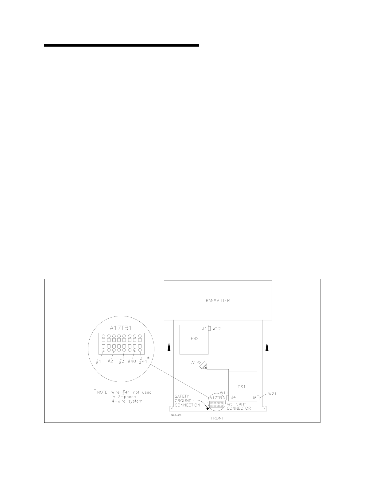
2.5.4.2 Power Supply Connections
First, remove the front cover panel from the power supply compartment at the
bottom of the transmitter. The power supply connection cables are either tied up in
the power supply compartment (in the bottom of the transmitter) or tied up with the
power transformers. The power supply should be rolled into position in front of the
transmitter. Do not roll it in yet. There are two separate supplies on the tray, PS1 is
in front and PS2 is in the rear. The following cables will need to be connected:
a. There are two ribbon cables W11 and W12 (blue) and one control voltage
cable W21 (gray with orange connector) hanging on the right side of the
power supply compartment.
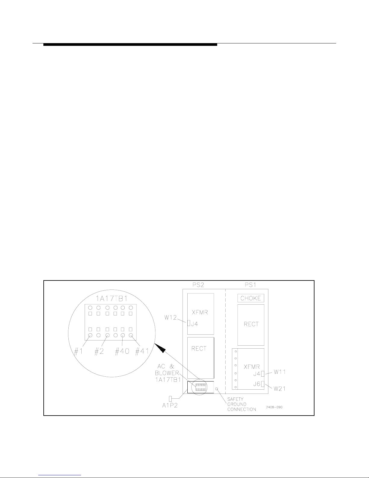
1. First connect W12 to J4 on the PS2 Rectifier Board. See Figure 2-1.
2. Now the supply can be rolled into the cabinet. Be sure to get the orange
AC input cables, #1, #2 and #3 and wires #40 and #41 out of the way
before rolling the power supply all of the way in. These are bundled on
the left side of the power supply compartment.
3. Connect W11 to J4 on the PS1 Rectifier Board.
4. Connect W21 (flat gray cable with orange connector) to J6 on the PS1
Rectifier Board.
b. The cable labeled A1P2 (gray multi-conductor cable with 12 pin gray connector)
plugs into its mating connector on the left wall of the power supply compartment.
c. Roll the power supply the rest of the way into the cabinet.
Figure 2-1 3-Phase Power Supply Top View
Page 27
888-2408-002 2-7
WARNING: Discon nect primar y power prior t o servicing .
Installation & Initial Turn-On
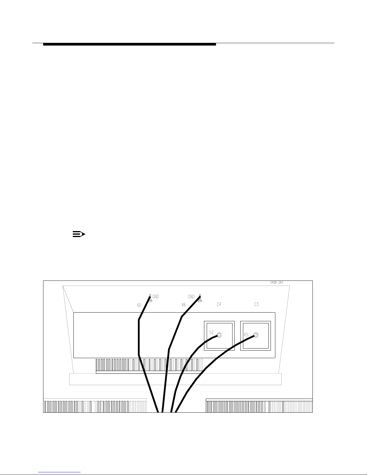
d. Wires 45 and 52 (large orange cables tied up with the transformers) connect to
the feed-thru terminals, C3 and C4 at the top of the power supply compartment. These are the 52Vdc outputs from the two supplies. See Figure 2-2. The
wires connect as follows:
• Wire #52 connects to C4 (on the left along with wire #81)
• Wire #45 connects to C3 (on the right along with wire #80)
e. Wires #1, #2, and #3 (orange cables tied up on the left side of the power sup-
ply compartment) and two smaller gray wires #40 and #41* plug into the gray
Wego block connector, A17TB1 on the front of the power supply tray (A17
designates a component on the power supply tray). See Figure 2-1. The Wego
block has 8 terminals labeled terminal #1 on the left and #8 on the right. The
connections are as follows:
• Wire #1 connects to terminal #1
• Wire #2 connects to terminal #3
• Wire #3 connects to terminal #5
• Wire #40 connects to terminal #7
• Wire #41* connects to terminal #8
(*Wire #41 is not used on 3 phase 4-wire system)
NOTE:
If these wires are not connected to the appropriate terminal on the
Wego block, as d esig nated on the Overall System Block Diagram , the
blower may not operate.
Figure 2-2 DC and Ground Connections for 3-Phase Power Supply
Page 28

2-8 888-2408-002
WARNING: Discon nect primar y power prior to servicing.
Installation & Initial Turn-On
f. To insert the wires into the Wego block, insert a screwdriver into the rectan-
gular slot above the wire hole then carefully lift. This will open the contact
inside the Wego block and the wire can be inserted. Be very careful not to let
the wire ends fray as the connectors are very close together and could cause a
short. The wire insulation should actually extend just inside the Wego block
hole.
g. The large orange ground wires, #46 and 60, coming from the top of each rec-
tifier assembly attach to ground studs at the top-front edge of the power supply compartment. It is located under the shelf which separates the power
supply from the PA compartment just above C3 and C4. See Figure 2-2.
h. Connect the safety ground wire to the stud on the front of the power supply
tray, just in front of A17TB1, See Figure 2-1.
i. Tighten the two hold down nuts located on the bottom front corners of the
power supply compartment. Re-install the front cover panel for the power
supply compartment.
2.5.5 Single Phase Power Supply Installation
Before installing the power supply check the primary ac tapping on the power
transformers as outlined below. Even if the transmitter was shipped with the power
supply installed, it would be a good idea to check the power supply tapping if
possible.
2.5.5.1 Power Transformer Tapping
The power transformers are tapped at the factory for the primary AC voltage
specified by the customer. This voltage should be documented in the factory test
data accompanying the transmitter and tagged at the ac contactor. However, the
voltage at the site and the transformer tapping should be verified by the installation
personnel. The input voltage and strapping chart is shown on the Overall System
Block Diagram along with the transformer schematic. V erification and/or re-tapping
will require opening the power supply access panel on the front of the transmitter
and rolling out the power supply if the transmitter was shipped with the power
supply already installed (this depends on where and how it is shipped).
Page 29
888-2408-002 2-9
WARNING: Discon nect primar y power prior t o servicing .
Installation & Initial Turn-On
2.5.5.2 Single Phase Power Supply Connections
First, remove the front cover panel from the power supply compartment at the
bottom of the transmitter. The power supply connection cables are either tied up in
the power supply compartment (in the bottom of the transmitter) or tied up with the
power transformers. The power supply should be rolled into position in front of the
transmitter. Do not roll it all the way in. The following cables will need to be
connected:
a. There are two ribbon cables and one power connector hanging on the right
side of the power supply compartment inside the transmitter. The ribbon
cables connect to J4 on the Rectifier Boards. The longer ribbon cable, W12
connects to the Rectifier Board on PS2 (nearest the back of the transmitter)
and should be connected first. Be sure to route this cable so it does not touch
the resistor standing up on top of the Rectifier heatsink. See Figure 2-3.
b. The shorter blue ribbon cable, W21 connects to the front Rectifier Board on
PS1. The power cable, W11 (the gray cable with the orange connector) connects to J6, on the Rectifier Board nearest the front of the transmitter.
c. The cable labeled A1P2 (gray and yellow multi-conductor cable with gray
connector) plugs into its mating connector on the left wall of the power supply compartment. Roll the power supply all the way into the cabinet.
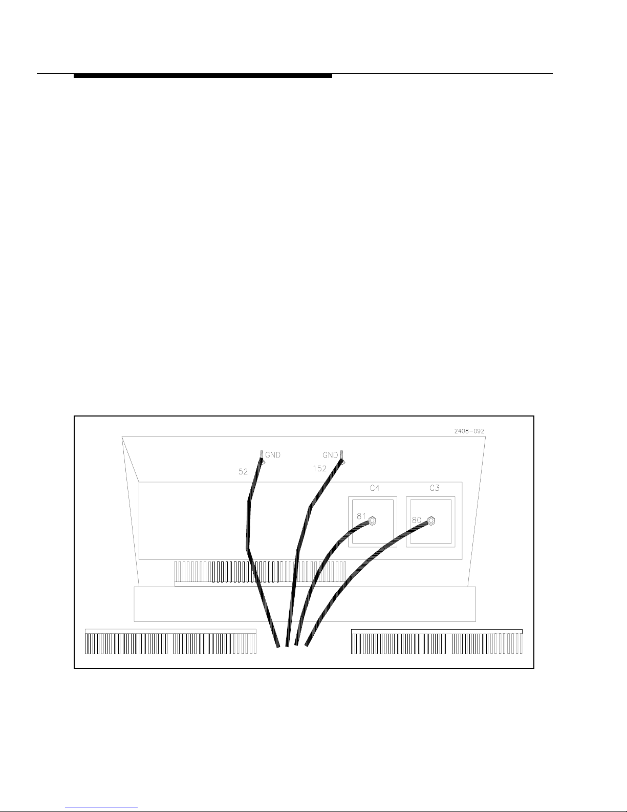
d. Wires 80 and 81 (large orange cables tied up with the transformers) connect to
the feed-thru terminals at the top of the power supply compartment. See Figure 2-4. The cables are dressed such that the shorter cable, 81 connects to the
left hand terminal and the longer cable, 80 connects to the right hand terminal.
Figure 2-3 Single Phase Power Supply Top View
Page 30
2-10 888-2408-002
WARNING: Discon nect primar y power prior to servicing.
Installation & Initial Turn-On
e. Wires #1 and #2 (orange cables tied up on the left side of the power supply
compartment) plug into the gray Wego block connector on the front of the
power supply tray. See Figure 2-3. Wire #1 goes to the left and #2 in the 3rd
hole from the left. Wires #40 and #41 are inserted into the 5th and 6th holes
respectively from the left. To insert the wires into the Wego block, insert a
screwdriver into the rectangular slot behind the wire hole and then carefully
push toward the rear of the transmitter. This will open the contact inside the
Wego block and the wire can be inserted. Be very careful not to let the wire
ends fray as the connectors are very close together and could cause a short.
The wire insulation should actually extend just inside the Wego block hole.
f. The large orange ground wires, #52 and 152, coming from the power supply
attach to the ground stud at the top-front edge of the power supply compartment. It is located under the shelf which separates the power supply from the
PA compartment, see Figure 2-4.
g. Connect the safety ground wire to the stud on the front of the power supply
tray, just in front of A17TB1, See Figure 2-3.
h. Tighten the two hold down nuts located on the bottom front corners of the
power supply compartment.
Re-install the front cover panel for the power supply compartment.
Figure 2-4 DC and Ground Connections for Single Phase Power Supply
Page 31

888-2408-002 2-11
WARNING: Discon nect primar y power prior t o servicing .
Installation & Initial Turn-On
2.5.6 Transmitter AC Connections
The ac input for the transmitter should be low impedance, 50/60 Hz, single or three
phase depending on transmitter phase supply with sufficient capacity to supply the
transmitter. Refer to the “Z2 Outline Drawing” in the drawing package for current
ratings, nominal fuse sizes and wire gauge for the 3 phase delta, 4 wire wye, and
single phase input voltage combinations.For more information AC power requirements see “Power Distribution for Optimum Transmitter Performance” at the
end of this section.
A customer supplied ac primary power disconnect or means to completely deenergize the transmitter primary circuit for servicing is necessary.
NOTE:
Harris does not recommend using circuit breakers for the main transmitter disconnect due to the inrush current during turn-on.
The recommended fuse type is class RK5, a dual element time delay fuse. Examples
are the Bussmann FRN-R (250V), FRS-R (600V), Littelfuse FLNR (250V), FLSR
(600V), and Ferraz gG fuses. If you prefer to use a circuit breaker in your
installation, select one with a motor-starting trip curve, similar to the RK5 curve for
fuses. This type of delayed response is needed in order to accommodate the
momentary in-rush current. This can be 300 to 600 amps, depending on the
transmitter model and AC configuration.
!
WARNING:
DISCONNECT AND LOCK OUT PRIMARY POWER TO THE TRANSMITTER
BEFORE PROCEEDING.
2.5.6.1 Information concerning some 360 to 416 volt systems
This transmitter is equipped with MOVs (metallic oxide varistors) which provide a
measure of protection against incoming overvoltage transients. However, the
selection of some of the MOVs relies upon knowing the approximate voltage from
each AC phase to ground. Unfortunately a few AC power systems around the world
do not have a direct connection to earth ground, thereby making it impossible to
predict the phase-to-earth ground voltage.
In a typical 380 volt system that has a connection to earth ground, each AC phase
will measure about 220 volts to ground. The phase-to-phase, and phase-to-ground
voltages should be balanced within a few percent.
However, in a system which has no direct connection to earth ground, each AC
phase will measure a voltage which follows no particular pattern. In such a case, the
Page 32
2-12 888-2408-002
WARNING: Discon nect primar y power prior to servicing.
Installation & Initial Turn-On
MOV protection may need to be modified. Please consult with an electrician if this
applies to your installation. If applicable, the phase-to-earth 275 volt MOVs in the
RV7 through RV13 and RV20 positions may be replaced with 510 volt MOVs
(Harris part number 560-0042-000, quantity 8).
For safety reasons, you also must install a 4 pole disconnect device if your neutral
line is not connected to earth ground.
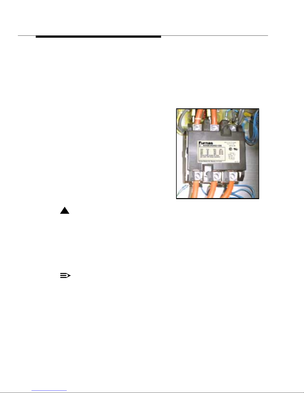
2.5.6.2 AC Input Connection
AC connections are made to the top of the main
contactor K1, located in the top righthand
corner in the back of the transmitter. Bring the
ac wires through the holes in the top of the
transmitter and connect to the top terminals on
contactor K1. Access is also available through
the bottom of the transmitter.
For 380VAC (342 - 432VAC) 3 Phase 4-wire
systems, there is also a large insulated standoff
located near the main contactor for the
NEUTRAL connection.
!
CAUTION:
THE NEUTRAL CONNECTION IS EXTREMELY IMPORTANT IN 380VAC 4
WIRE APPLICATIONS. BY VIRTUE OF THE SINGLE PHASE LOADS
WITHIN THE TRANSMITTER, THE SYSTEM IS NOT ENTIRELY
BALANCED, REQUIRING NEUTRAL CURRE NT TO MAINTAIN PROPER
PHASE TO NEUTRAL VOLTAGES. A POOR NEUTRAL CONNECTI ON
COULD CAUSE DAMAGE TO THE SINGLE PHASE ELEMENTS IN THE
TRANSMITTER.
NOTE:
The NEUTRAL connection is NOT required for 208/220V AC 4-wire
WYE source voltage and should not be run to the transmitter.
There is no connectio n in the tra nsmitter for the neutra l connection (for
this application) and it sho uld not be connected to chassi s ground. The
power supply transformers in the transmitter will be configured as
delta for this application.
Page 33

888-2408-002 2-13
WARNING: Discon nect primar y power prior t o servicing .
Installation & Initial Turn-On
2.5.6.3 Grounding
The importance of a good grounding system and lightning protection can hardly be
overemphasized for reasons of personnel safety, protection of the equipment, and
equipment performance. The following is only a brief overview.
Lightning and transient energy via the power line or tower connections can impose
serious threats to your personal safety as well as damage the equipment. For these
reasons you should have a good protective earthing system to divert these forms of
energy to earth ground. Proper grounding of the equipment also guards against
electrical shock hazards that would exist if the equipment failed in a way which put
a hazardous voltage on the chassis.
A good grounding system should include substantial grounding at the tower base
using copper ground rods and/or a buried copper ground screen, with copper strap
used to connect the tower base to earth ground. A low impedance will help carry
lightning current directly into the ground instead of into your building. Additionally,
coax shield(s) should be electrically connected to and exit the tower as near to the
bottom as practical to minimize the lightning voltage potential carried by the coax
into your building.
For coaxes, a single point of entry into the building is best, with all connected to a
common grounding plate (or bulkhead panel) having a low impedance connection
to the building perimeter ground. Wide copper straps should be used for making the
connection from the common grounding plate to earth ground.
A common grounding plate is also the best location for coaxial surge protectors for
sensitive equipment such as an STL receiver. Ideally, this plate should also be the
entry point for all signal lines, and serve as a single point ground for AC power
surge protection.
A good ground system should include perimeter grounding of the transmitter
building using copper ground rods and copper strap. There should also be a copper
strap running from tower ground to the building perimeter ground.
Good grounding and shielding will help keep stray RF current to a minimum. RF
interference usually shows up in one of several ways, intermittent problems with
digital or remote control circuits, audio feedback or high pitched noise. Even a
small amount of non-shielded wire makes a very efficient antenna for RF and
transient energy. If RF is allowed into the audio equipment, it can be rectified and
may show up as noise or feedback. Wire and cable shields should normally be
connected at both ends to the equipment chassis.
Page 34

2-14 888-2408-002
WARNING: Discon nect primar y power prior to servicing.
Installation & Initial Turn-On
A ground strap attachment point is located on the top, right rear, of the cabinet (use
four 1/4-20 brass screws with brass washers). Use this connection when utilizing a
single point grounding system, attaching your ground strap to the common
grounding plate. An alternate ground connection is a short copper strap on the back
of the Platinum Z transmitter, on the bottom right side. Unfold this strap and
securely bolt or silver solder it to the building ground. This strap can be removed
from the bottom and used at the top.
A grounding stud is also provided near the AC input connections in the upper
portion of the Platinum Z transmitter . Use this connection for the power line ground.
It is located above the low voltage power supply board.
2.5.6.4 Low Voltage Power Supply and Blower
The Low Voltage Power Supply and the blower motor operate from any voltage
within the specified range of the tapping chart without re-tapping.
2.5.6.5 Exciter AC Voltage Selection
Once the site voltage has been checked, verify that the exciter(s) are set for the
proper input ac voltage. For verification, the selected voltage should be visible next
to the ac power cord connection on the rear of the exciter. For information on setting
the exciter voltage, refer to the exciter technical manual.
2.5.7 RF Output Connection
The station transmission line may now be connected at the 1 5/8" EIA flange
located on top of the transmitter. Be sure the bullet seats correctly and all flange
bolts are tight. Make sure the clamp at the top of the harmonic filter is tightened.
2.5.8 Audio Input Connections
All audio signals connect directly to the back of the exciter(s) by routing the cables
through the top or bottom of the transmitter. The exciter technical manual has all of
the information pertaining to audio connections, input levels and adjustments. Be
sure to leave enough cable slack to allow the exciter to be pulled all of the way out
on the rack slides.
Page 35

888-2408-002 2-15
WARNING: Discon nect primar y power prior t o servicing .
Installation & Initial Turn-On
2.5.9 External and Failsafe Interlock Connections
The transmitter is shipped with two jumpers installed on TB1, the Remote Control
Interface terminal strip: TB1-7 to TB1-6(GND) is for External Interlock and TB1-8
to TB1-10(GND) is for Failsafe.
2.5.9.1 External Interlock Connection
To use the External Interlock connection, remove the jumper between terminals
TB1-7 to TB1-6(GND), then connect external interlock wires. A contact closure
allows the transmitter to operate. When the external interlock connection is opened
the P A power supplies, blower and exciter turn off, the status of the transmitter is set
to off. The external interlock wires can also be connected directly to the Life
Support Board at J4-7 and J4-10 if it is desired to have the interlock completely
separate from the remote control interface. The TB1 and J4 connections are in
parallel. Only one or the other is to be used. NOTE: The transmitter will require an
ON command after the external interlock connection is restored.
!
CAUTION:
TO CONNECT TO THE WAGO BLOCK, J4 ON THE LIFE SUPPORT BOARD
REQUIRES PRESSING A SCREWDRIVER INTO THE RECTANGULAR
SLOT ON THE FRONT SIDE OF THE BLOCK SO THE WIRE CAN BE
INSERTED FROM THE REAR. BE SURE TO PROPERLY SUPPORT THE
BOARD SO THAT IT IS NOT BENT OR STRESSED IN ANY WAY WHILE
INSERTING THE WIRES.
2.5.9.2 Failsafe Interlock Connection
To use the failsafe interlock connection, remove the jumper between TB1-8 to TB110(GND), then connect failsafe interlock wires. A contact closure allows the
transmitter to operate. The Failsafe connection can be used for any application
which requires muting the transmitter RF output. When the failsafe interlock
connection is open the fan is set to high, the IPA and exciter are muted. The failsafe
interlock wires can also be connected directly to the Life Support Board at J4-7 and
J4-8 if it is desired to have the failsafe interlock completely separate from the
remote control interface. The TB1 and J4 connections are in parallel. Only one or
the other is to be used. NOTE: The transmitter will transmit when the failsafe
interlock connection is restored (if it was transmitting when the failsafe connection
was opened).
Page 36
2-16 888-2408-002
WARNING: Discon nect primar y power prior to servicing.
Installation & Initial Turn-On
2.5.10 Initial Turn-on
Each transmitter is thoroughly checked out during factory final test but adjustment
may be required during installation due to shipping, variations in primary power,
antenna systems, or transmission line differences. Any remote or extended control
connections should be connected only after the transmitter is checked out and fully
operational. Refer to the Factory Test Data Sheets supplied with the transmitter for
typical meter readings. The transmitter was checked into a 50-ohm resistive load at
the Factory.
The Transmitter ON-OFF sequence is controlled by three separate buttons:
• HIGH
• LOW
• OFF
These buttons are located on the front panel of the Controller.
STEP 1 Activate the STATION AC POWER source to the transmitter.
STEP 2 Turn on the low voltage power supply breaker, CB1, located in the
rear of the transmitter cabinet in the upper right-hand corner. There
are 6 green LEDs on the Low Voltage Supply board which should be
illuminated. Close and secure the rear door.
STEP 3 Verify that the two LCD displays on the front of the controller are
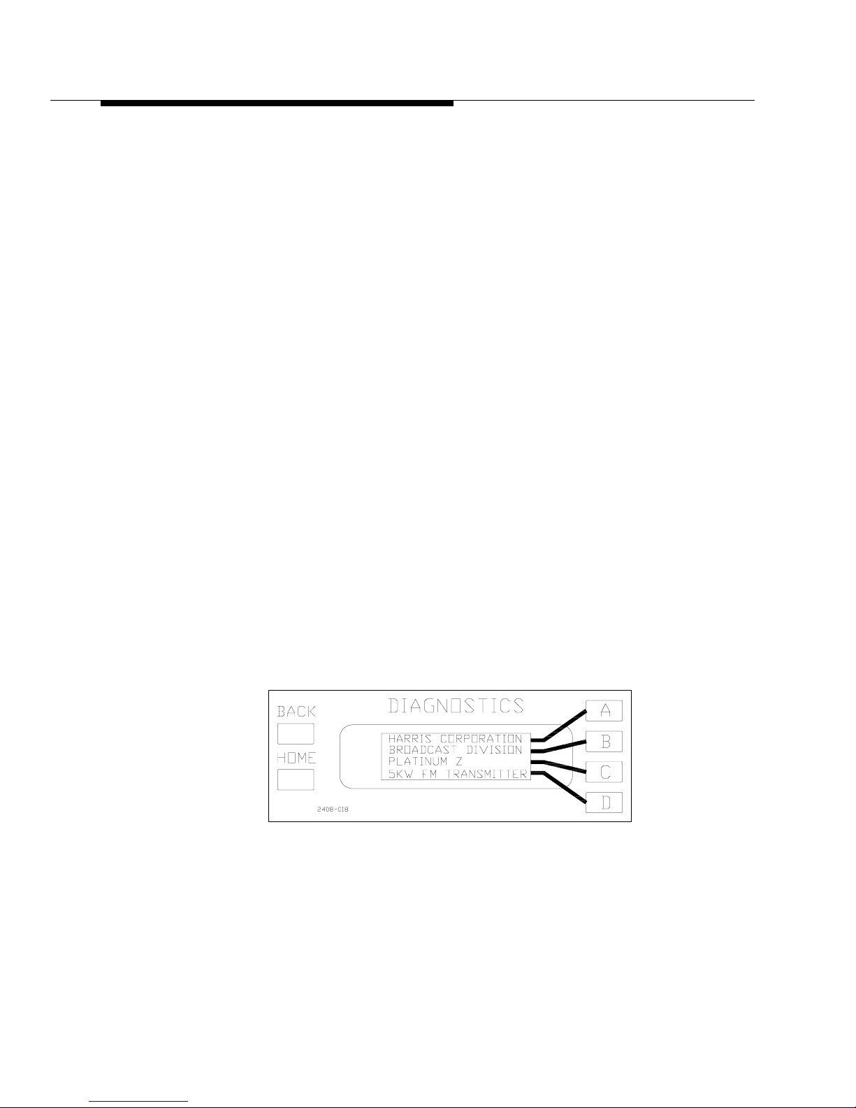
active. The Diagnostics display should look like Figure 2-5. The
Fault LED on the front panel will be lit, since the modules are not
installed yet, and should be ignored at this point.
Figure 2-5 Default Display
STEP 4 Press the PA VOLTS button on the front panel of the controller.
STEP 5 Press the LOW power ON button on the front of the controller, but
be ready to quickly press the off button if necessary. The PA VOLTS
reading on the front panel should be above 40Vdc and the blower
should come on at HIGH Speed.
Page 37

888-2408-002 2-17
WARNING: Discon nect primar y power prior t o servicing .
Installation & Initial Turn-On
NOTE:
If the blower does not run, check the position of wires #1, #2 and #3
for 3-phase or wir es # 1 a nd #2 for a single phase, a t A17TB1. If these
are connecte d in the wrong positi on, the fan may not operate (this is
also true for the single phase transmitter due to switching on the Low
Voltage Supply Board). Also check blower fuses F1 and F2 located in
the bottom deck of the front PA compartment (F2 not used in 3 phase
4-wire systems).
STEP 6 If the PA VOLTS reading appears okay then shut the transmitter off
and insert the PA and IPA Modules as directed below. See Figure 2-6
and Figure 2-7.
STEP 7 PA Module installation - Four PA modules and 1 IPA module are
inserted in the front of the cabinet and four PA modules are inserted
in the back of the cabinet. The PA and IPA modules are symmetrical
which means they can be inserted with either side of the module
facing up and cannot be inserted improperly. The modules should
only require a minimal amount of force for insertion into the card
edge connectors. If they do not slide in easily, check the connectors
on the combiner boards, and visually inspect the com biner asse mbl y
to verify nothing has come loose and/or moved during shipment.
!
WARNING:
THE PA MODULES ARE DESIGNED TO HANDLE VERY HIGH TEMPERATURES
AND MAY BE EXTREMELY HOT. DO NOT TOUCH THE MODULES WITH BARE
HANDS AFTER THE TRANSMITTER HAS BEEN RUNNING, ESPECIALL Y IN HIGH
AMBIENT TEMPERATURE ENVIRONMENTS.
STEP 8
Optimization - The Factory Test Data Sheet contains the serial
numbers of each of the P A and IPA modules. The data sheet also tells
which slot each of the PA modules were connected into during
factory testing. While it is Not Critical to operation, the transmitter
readings may be closer to the data sheet if the PA and IPA modules
are placed in the same positions as during factory testing. The
module serial number tag should be on top of the module when
inserted into the transmitter.
!
CAUTION:
EACH MODULE HAS TWO CAPTIVE THUMBSCREWS WHICH MUST BE
TIGHTENED TO ASSURE PROPER MODULE OPERATION. THEY SHOULD
BE FINGER TIGHT. IF A SMALL SCREWDRIVER IS USED, BE SURE NOT
TO OVERTIGHTEN.
Page 38
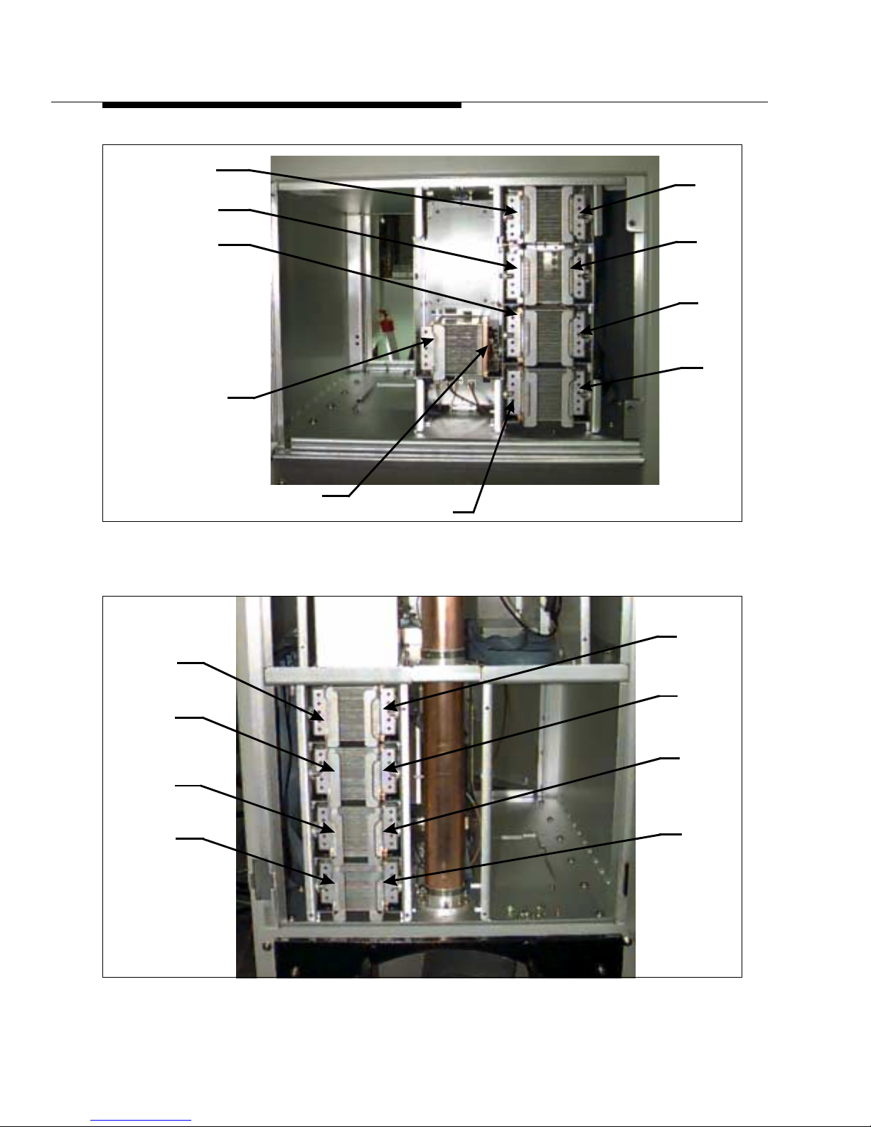
2-18 888-2408-002
WARNING: Discon nect primar y power prior to servicing.
Installation & Initial Turn-On
Figure 2-6 PA Compartment Front View
Figure 2-7 PA Compartment Rear View
A1
A2
A3
A4
IPA_AB1
IPA_AB2
B1
B2
B3
B4
B5
B6
B7
B8
A5
A6
A7
A8
Page 39
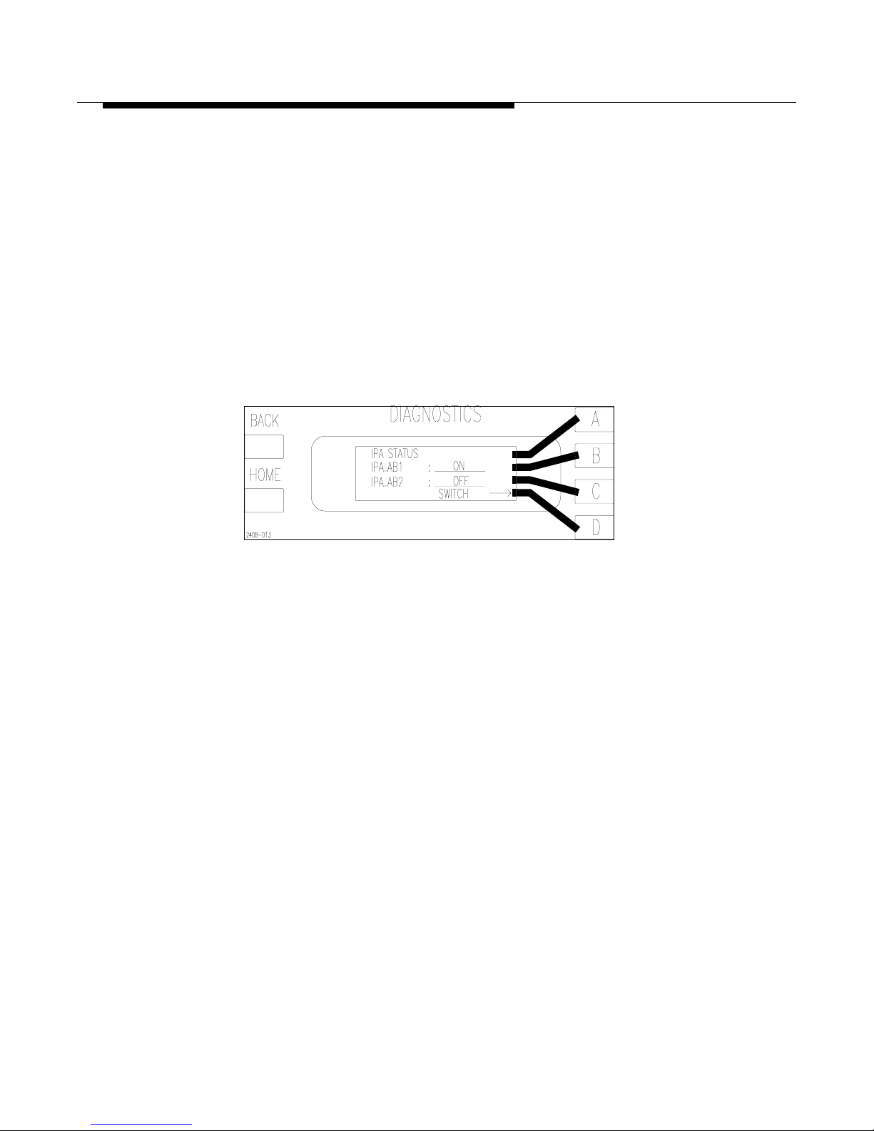
888-2408-002 2-19
WARNING: Discon nect primar y power prior t o servicing .
Installation & Initial Turn-On
STEP 9 F or the dual IPA configuration, the IPA will be identical to any of the
PA modules and may be plugged in with either side up in the IPA
slot. To see which IPA is active press [HOME, STATUS D,B]. This
should bring up the screen shown in Figure 2-8. If the transmitter is
configured with only a single IPA, then one half of the module will
be empty. It is recommended that the IPA module be inserted with
the amplifier on the right side of the heatsink. This places the
amplifier in the IPA_AB1 position (the default for the controller). If
the IPA is on the left side of the heatsink when inserted, then
IPA_AB2 will have to be selected before operating the transmitter.
To select IPA_AB2 press the [D] or switch key to toggle from
IPA_AB1 to IPA_AB2 and back.
Figure 2-8 IPA Status and Manual Switch
[HOME, STATUS D,B]
STEP 10 With all of the modules installed, the Fault LED on the controller
front panel should be flashing at this point. This indicates that there
are inactive faults in the fault log which need to be cleared at this
time. To reset the Fault Log press [FAULT, C, and then D for YES].
This will erase all inactive faults i n the Fault Log and the front panel
Fault LED should be off. If the “FAULT” LED on the front panel of
the controller is not lit, then proceed to the next step.
If the “FAULT” LED, on the front panel of the controller, is
illuminated (not flashing), use the Fault Log to find the active
fault(s) and refer to Section VI, Troubleshooting for information on
how to track down the problem.
STEP 11 Turn the transmitter back ON at LOW power. Verify that the exciter
power is the same as the factory test data sheet. This can affect
performance.
The fan will run at high speed for 1 minute then will automatically
switch to low speed provided there are no faults. Any fault will
cause the fan to automatically switch to high speed. There is also an
option to force the fan speed to HIGH in the Configuration menus of
the Diagnostics Display. See Table 2-14 on page 2-24.
Page 40

2-20 888-2408-002
WARNING: Discon nect primar y power prior to servicing.
Installation & Initial Turn-On
STEP 12 At this point, if there are no faults, verify that the transmitter display
readings closely resemble those on the factory test data sheet for
LOW power. If the “FAULT” LED comes on, go to the Fault Log in
the Diagnostics Display to find out which fault has been activated
and refer to Section VI, Troubleshooting. If everything looks okay,
proceed to the next step.
STEP 13 Press the HIGH power ON button on the front panel of the controller.
If there are no faults, again verify all of the transmitter display
readings against those in the factory test data sheet.
STEP 14 This step is optional, as it simply makes the transmitter FWD PWR
% meter read 100% at the customer specified Transmitter Power
Output (TPO), which should already be factory set. This will not
change the kW reading on the FWD PWR display.
a. Set the power to the desired TPO using the raise and lower but-
tons.
b. Go to the 100% TPO SET screen [HOME,MORE,CONFIGU-
RATION B,A] and set the power level to your TPO. Press
[BACK] to update and store the new information.
c. The front panel FWD PWR reading should be 100%. You may
also want change the MAX HIGH and MAX LOW power settings to something more in line with your new TPO as well.
MAX HIGH sets the maximum power level when the HIGH ON
button is pressed, while MAX LOW sets the maximum power
level when the LOW ON button is pressed. The procedure for
changing power limits is given in Section V, Maintenance and
Alignments.
The initial turn on is now complete.
Page 41
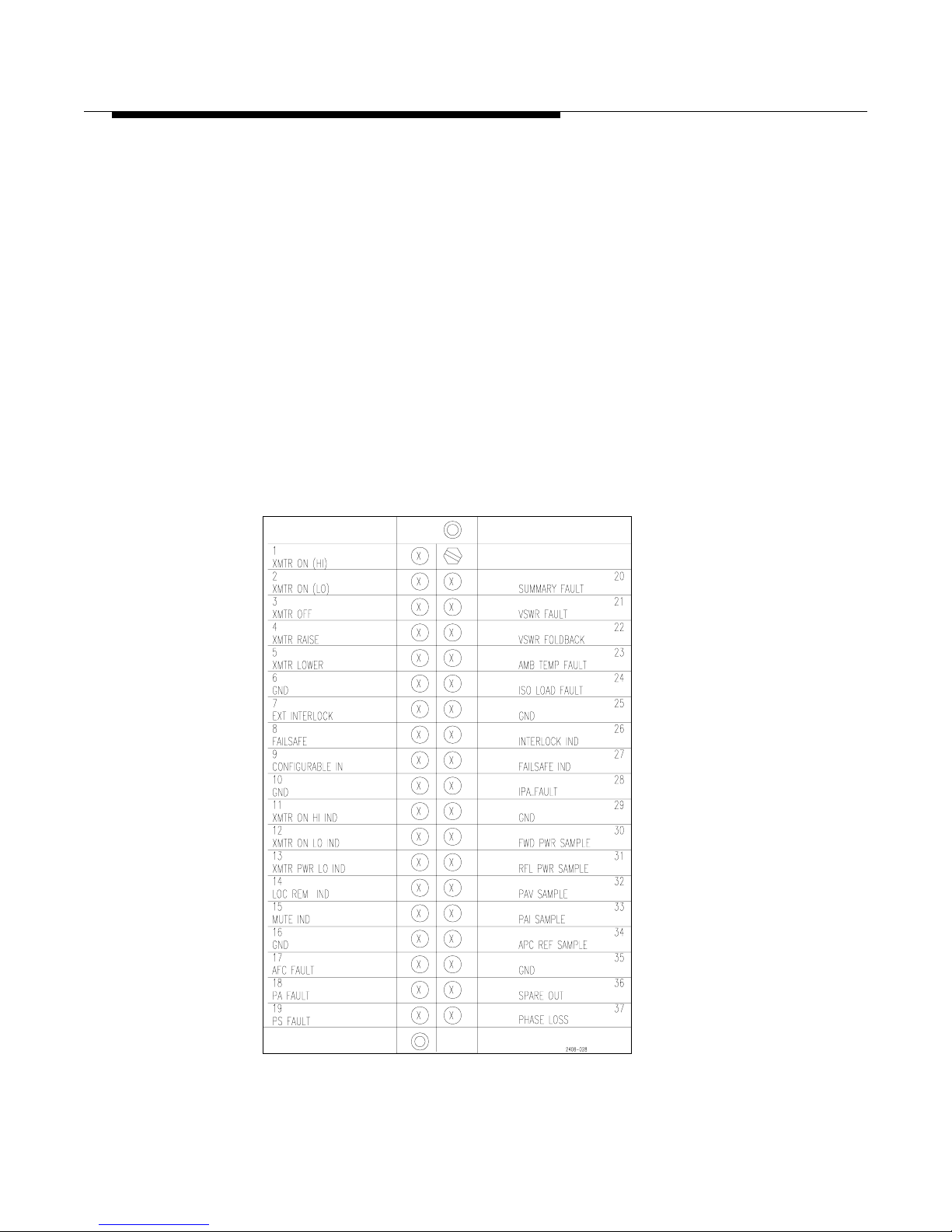
888-2408-002 2-21
WARNING: Discon nect primar y power prior t o servicing .
Installation & Initial Turn-On
2.5.11 Remote Control Connections
The Platinum Z5 Transmitter may be operated by remote control by installing a
remote control system. If the transmitter is to be remote ly controll ed, it is i mportant
to initiate thorough inspection and maintenance procedures at the transmitter
location. Installation of equipment to monitor temperature and humidity at the
remote transmitter site is also recommended.
Terminations provided in the Platinum Z5 Transmitter allow remote control of the
transmitter functions by connection to terminals on terminal board A1TB1. TB1 is a
38 pin Terminal strip with a D-connector on the back which connects to J20 on the
controller. Table 2-1 on page 2-28 contains a complete listing and explanation of
connections for TB1. Figure 2-9 shows TB1 pinout and connections. TB1 is located
in the upper left side in the rear of the transmitter when viewing from the back.
Use shielded cable for the remote control lines and/or install it in a metal conduit. It
is acceptable to install it in the same conduit as the exciter input cables.
Figure 2-9 TB1 Customer Interface Connections
Page 42
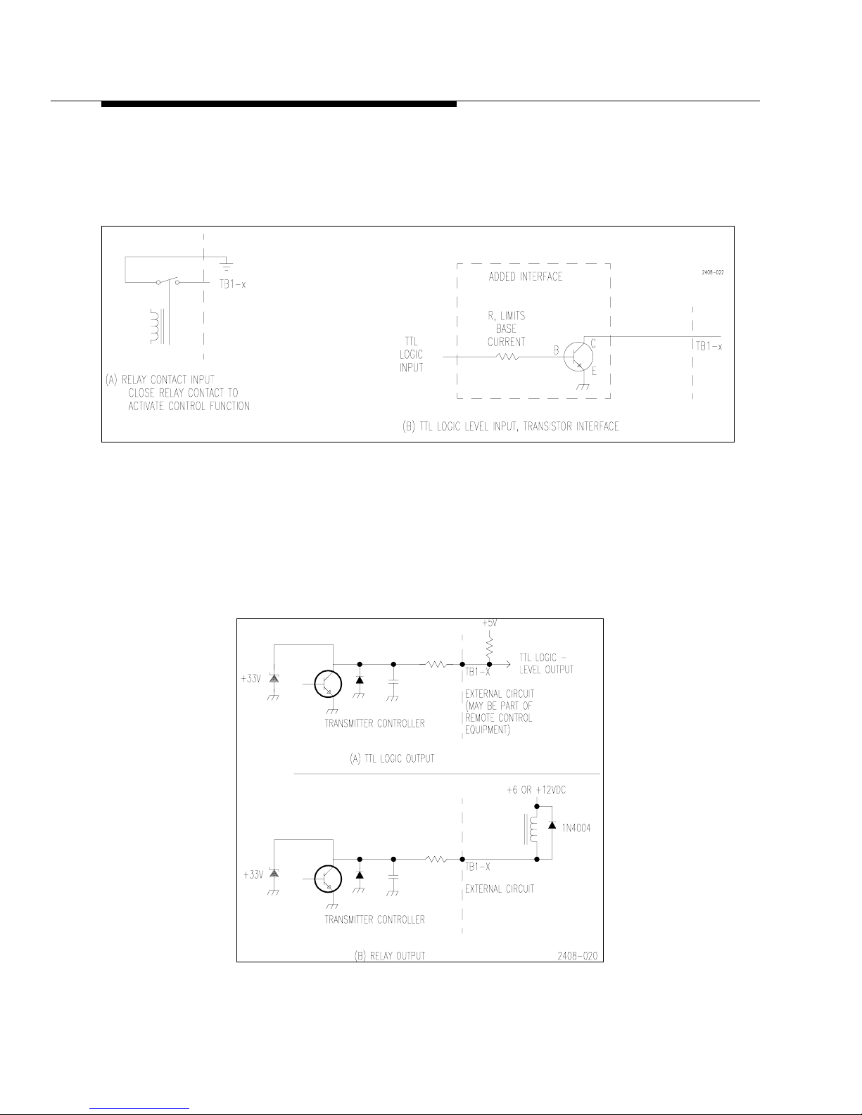
2-22 888-2408-002
WARNING: Discon nect primar y power prior to servicing.
Installation & Initial Turn-On
2.5.11.1 Control Inputs
Input control lines are standard ground switching inputs. The inputs can be operated
by relay contact or transistor switching. See Figure 2-10.
Figure 2-10 Ground Switching for Remote Control Lines
2.5.11.2 Status Ouputs
The status output lines on TB1 are transistor type - open collector. Figure 2-11(A)
illustrates how to interface TB1 outputs with TTL logic circuits. Figure 2-11(B)
illustrates how to interface TB1 with an external relay.
Figure 2-11 TTL Logic and Relay Status Outputs
Page 43
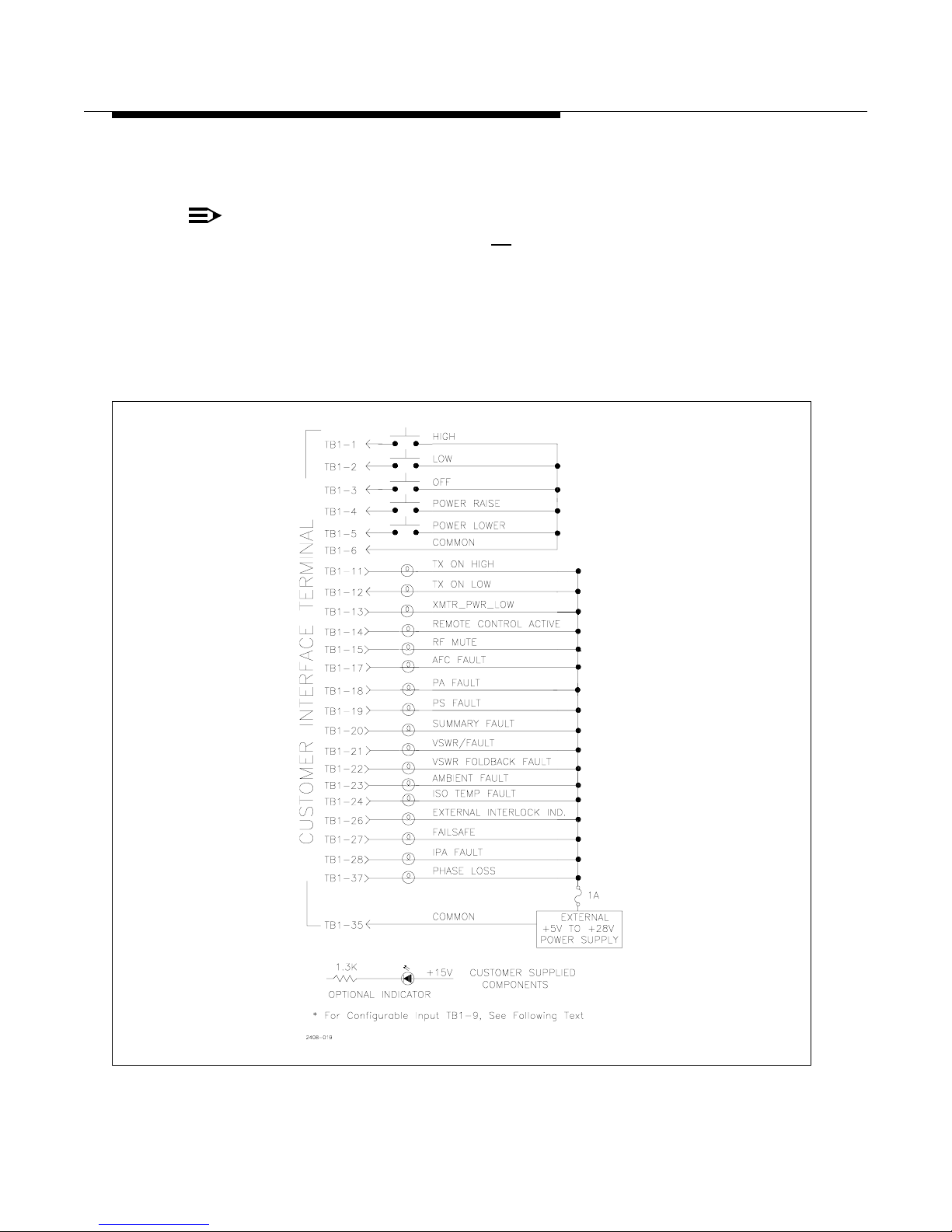
888-2408-002 2-23
WARNING: Discon nect primar y power prior t o servicing .
Installation & Initial Turn-On
A series resistor and LED can also be used for extended status indications.
Maximum external supply voltage should not exceed +28Vdc.
NOTE:
Maximum status line current is 25 mA. If the output is used to drive a
small printed circuit board type re lay, check current requirements for
relay coil and be sure to install a circuit protection diode across the
coil. A 1N4004 or equivalent will work.
Figure 2-12 shows typical remote/extended control and status connections.
Figure 2-12 Remote/Extended Control and Status Connections
Page 44
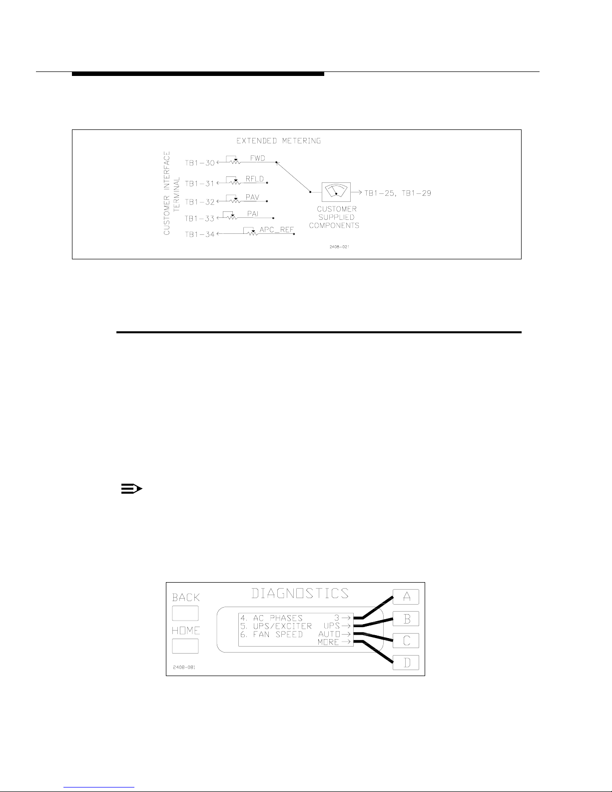
2-24 888-2408-002
WARNING: Discon nect primar y power prior to servicing.
Installation & Initial Turn-On
Extended metering can also be connected to TB1 terminals. See Figure 2-13 for an
example of extended metering connections.
Figure 2-13 Extended Metering
2.6 UPS IN/Remote Exciter Select,
Configurab l e In pu t TB1 - 9
The remote input at TB1-9 is a software configurable input which is set via the
Diagnostics Display Menu. It can be used as either a UPS Mode select input or as a
Remote Exciter select when a second exciter is installed in the transmitter. To
configure the input using the Diagnostics Display Menu press [HOME, MORE,
CONFIGURATION A,D]. This should bring up the screen shown in Figure 2-14.
The default setting is shown as “UPS”. This means the input is ready to be used as
the UPS Mode select. To use TB1-9 as a Remote Exciter Select input press [B]. This
will toggle the display to read “EXC”. This re-configures the TB1-9 input so that
when it is pulsed low momentarily, the transmitter will switch to the other exciter.
NOTE:
This input is simply a switch command and does not care which
exciter was on the ai r to be gi n with. For example, if the Main exciter i s
on the air, then it will switch to the alternate, but if the alternate is on
the air it will switch to the main exciter.
Figure 2-14 Configurable Input Select
[HOME, MORE, CONFIGURATION A,D]
Page 45
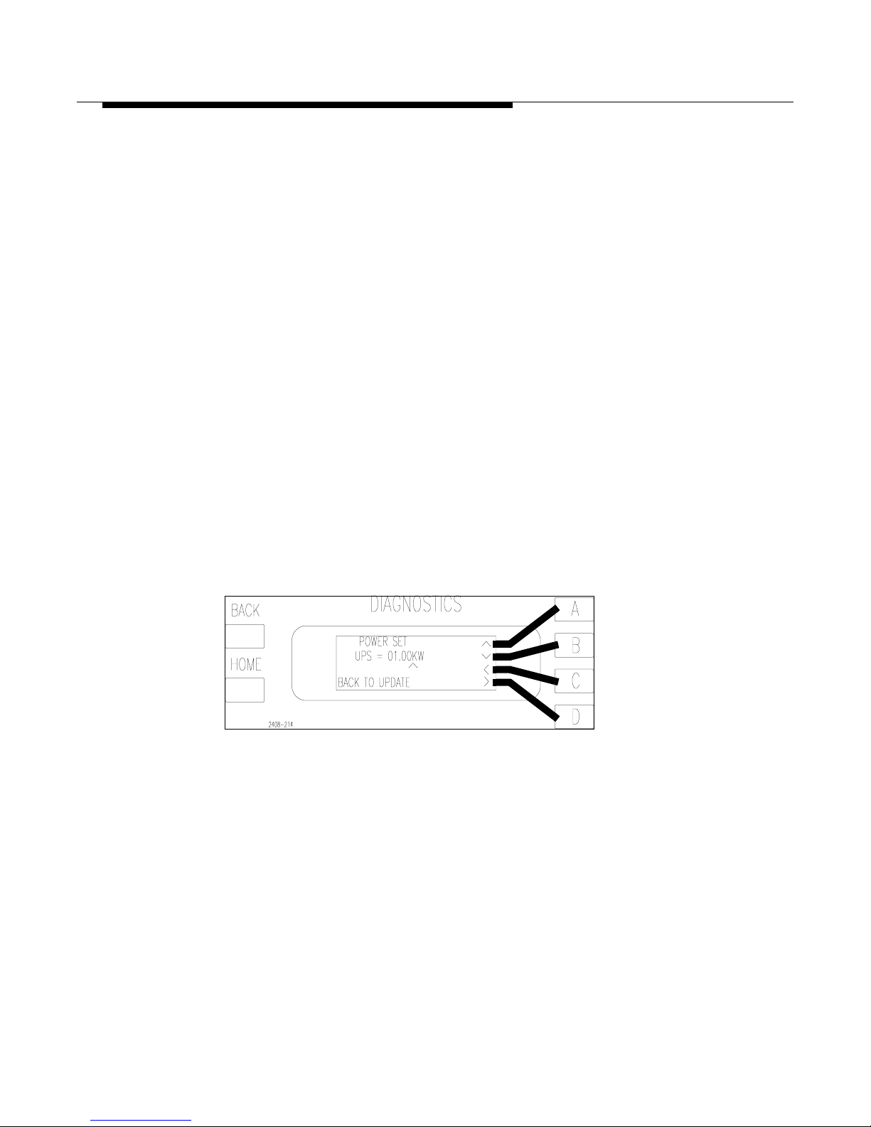
888-2408-002 2-25
WARNING: Discon nect primar y power prior t o servicing .
Installation & Initial Turn-On
2.6.1 Using an Uninterruptable Power Supply or UPS
If the transmitter is backed up with a UPS, to keep it operating during an ac power
failure, then the logical thing to do i s to lower the transm itte r power to conse rve the
UPS for as long as possible. Therefore, during an ac power failure, the transmitter
has the ability to automatically operate at a reduced power level when backed up by
a UPS or even a generator if so desired.
When the UPS is activated, TB1-9, the remote control interface terminal strip, must
be pulled low. This will take the transmitter to the preset UPS power level which is
factory set for 2.5kW, via software in the Diagnostics Display System. However, if
the transmitter is operating in LOW power when the UPS mode is activated, then the
transmitter will stay at the LOW power level unless the UPS level is set lower. For
example, if LOW power is set for 2kW and UPS is set for 2.5kW , the transmitter will
stay at the LOW power level of 2kW. If the transmitter is operating at HIGH power
when the UPS mode is activated then it will drop to the UPS power setting.
2.6.1.1 Setting The UPS Power Level
The setting of the UPS power level is done in the software of the Diagnostics
Display Menu. To set the UPS power level press [HOME, MORE,
CONFIGURATION B,D,A] see Figure 2-15. Once the new UPS power level is set
press [BACK] to save the new information. Pressing [HOME] instead will cancel
any changes made and take you back to the main menu.
Figure 2-15 UPS Power Set
[HOME, MORE, CONFIGURATION B,D,A]
Page 46
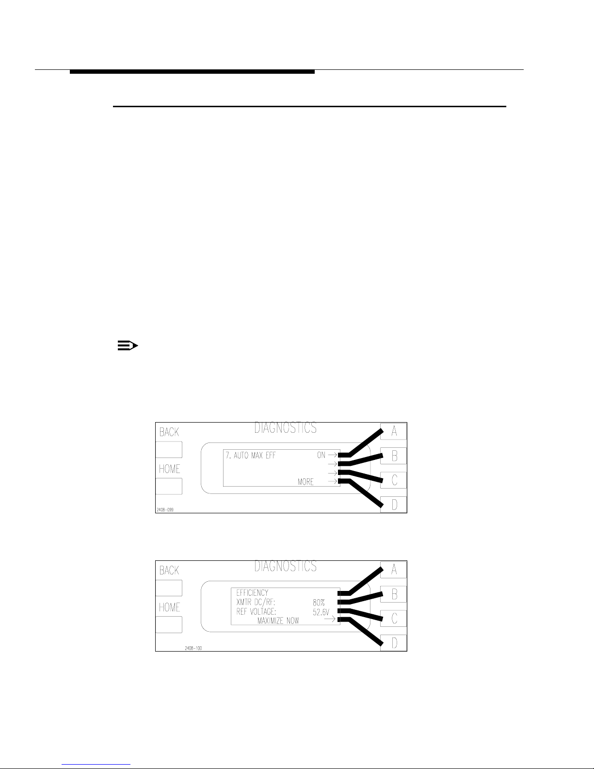
2-26 888-2408-002
WARNING: Discon nect primar y power prior to servicing.
Installation & Initial Turn-On
2.7 Optimizing Efficiency
The transmitter has the ability to Manually or Automatically optimize its own
operating efficiency. It is not a requirement, and the transmitter will meet all
specifications without activating this function. When activated, the controller will
adjust the transmitter operating parameters to get the best possible efficiency. The
user must select whether the function is in Manual or Automatic mode via the
Diagnostics Display Menus. To select the mode press [HOME, MORE,
CONFIGURATION A,D,D then A to Toggle: ON for Auto and OFF for Manual].
See Figure 2-16.
• Automatic Mode - When AUTO mode is selected, the transmitter will automati-
cally optimize the efficiency every 12 h ours if there are no active f aults present. This
is the recommended mode of operation and is the default mode from the factory.
• Manual Mode - In the Diagnostics Display, under Configuration, there is a
menu screen which can be used to optimize the transmitter efficiency. To optimize efficiency press [HOME, METERING D,C then D for Maximization]. See
Figure 2-17.
NOTE:
The REF VOLTAGE in Figure 2-17 is merely an internal reference
point the controller uses to reduce the supply voltage in optimized
mode. This reading is usually in the low 40 ’s when the transmitter is
optimized (well below the actual supply voltage).
Figure 2-16 Configuring Auto Max Efficiency
[HOME, MORE, CONFIGURATION A,D,D]
Figure 2-17 Efficiency Status
[HOME, METERING D,C]
Page 47
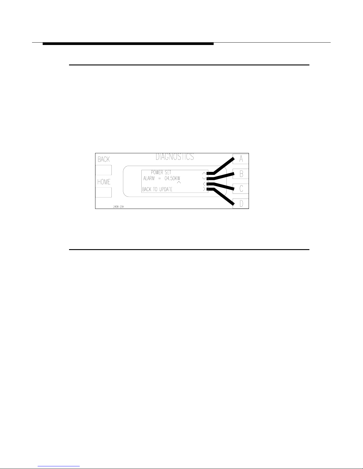
888-2408-002 2-27
WARNING: Discon nect primar y power prior t o servicing .
Installation & Initial Turn-On
2.8 Setting the Low Power Alarm
The transmitter has a low power alarm output for a remote control system. The
power level at which this remote alarm output is triggered, at TB1-13
XMTR_PWR_LO_IND, is selectable in the Configuration Menus. T o set this power
level press [HOME, MORE, CONFIGURATION B,D,B]. This should take you to
the screen in Figure 2-18. Set the power level at which you want the alarm to
become active and press [BACK] to save changes. For a complete listing of all
configurable parameters see “System Configuration and Calibration” in Section VI,
Troubleshooting.
Figure 2-18 Low Power Alarm Set Screen
2.9 Jumper Settings for Installation of a Harris Exciter
The following is for installing an exciter other than the one or tw o which came with
the transmitter . Any exciter te sted and shipped with the transmitt er will have already
been configured properly for the transmitter and should not require any jumper
changes. Table 2-2 includes all relevant jumper placement for the transmitter and
the following exciters:
• Digit CD Exciter with 994-9410-004 Part Number
• Digit Exciter with 994-9410-002 Part Number
• SuperCiter
• THE-1
Mounting Kits are available for each of the exciters listed.
Page 48
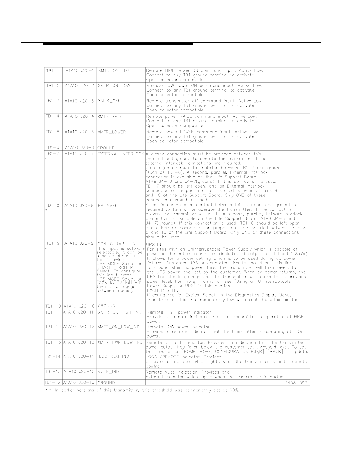
2-28 888-2408-002
WARNING: Discon nect primar y power prior to servicing.
Installation & Initial Turn-On
Table 2-1 TB1 Remote Control Interface Conn ections
Page 49
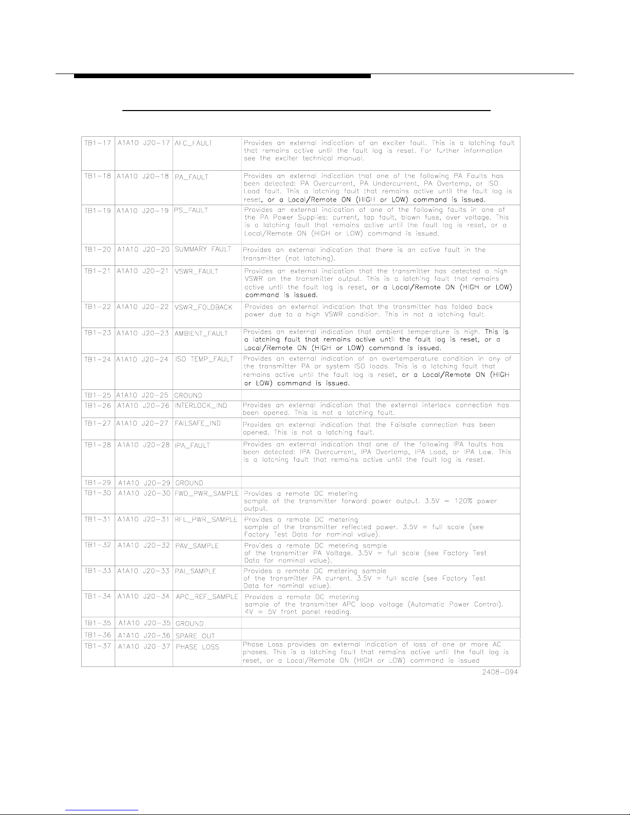
888-2408-002 2-29
WARNING: Discon nect primar y power prior t o servicing .
Installation & Initial Turn-On
Table 2-1 TB1 Remote Control Interface Connect ions (continued)
Page 50
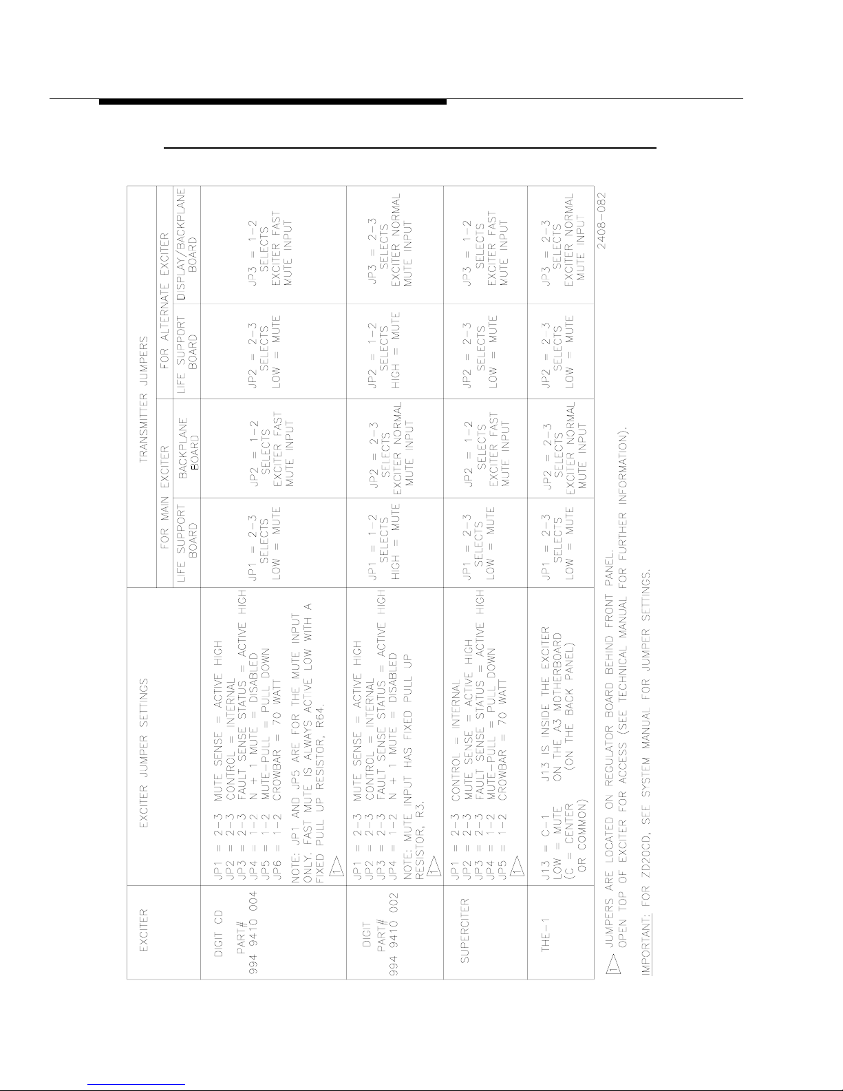
2-30 888-2408-002
WARNING: Discon nect primar y power prior to servicing.
Installation & Initial Turn-On
Table 2-2 Jumper Setting for installation of a Harris Exciter
Page 51

888-2408-002 2-31
WARNING: Discon nect primar y power prior t o servicing .
Installation & Initial Turn-On
2.10 Power Distribution for Optimum T ransmitter
Performance
This section is applicable to the three phase supplies only, as well as other three
phase equipment. For many years HARRIS engineers have recommended that the
three phase power distribution system should be either a closed delta or WYE
configuration to provide better radio and television transmitter performance by
helping prevent line unbalance. Operation with substantial voltage unbalance from
line to line results in higher than normal signal-to-noise ratio in the transmitter
output signal, increased three phase transformer heating, and hot three phase
motors.
2.10.1 Overheating from Line Unbalance
Even a device as simple as a three phase motor should be operated from a power
line in which the voltage is balanced within 1%. It takes only a 3.5% line unbalance
to produce a 25% increase above normal temperature. A 5% unbalance will cause
destructive temperature rises of 50% greater than normal!
Similar characteristics can be expected in the windings of a three phase power
transformer down inside the cabinet of your transmitter. Transformers and motors
can be designed with extra safety features where thermal rise is limited to
acceptable levels; however, in this case, other transmitter parameters cannot be
made acceptable at a reasonable cost.
2.10.2 Transmitter Noise Performance
The most difficult parameter to meet with power line unbalance is transmitter noise
performance. Most large transmitters use six-phase or twelve-phase high voltage
power supplies. The energy storage capacitors are expensive to install and large
stored energies make destructive faults inevitable. A good design will have
sufficient energy storage capacitors to meet the specified signal-to-noise but not
much more. When the equipment is then operated from an unbalanced line, the
power supply ripple frequency will be twice the line frequency instead of six to
twelve times. It becomes obvious that it would take three times as much energy
storage to achieve the original performance goal.
2.10.3 The Causes of Line Unbalance
How does a line unbalance occur? It is a rare case in which a large commercial
power producer would generate unbalanced voltage, so we must look elsewhere in
the system. When you have large single phase power users on a power line this can
cause uneven distribution of the line currents in the system. Uneven currents
through balanced impedances will result in line-to-line voltage unbalance.
Page 52
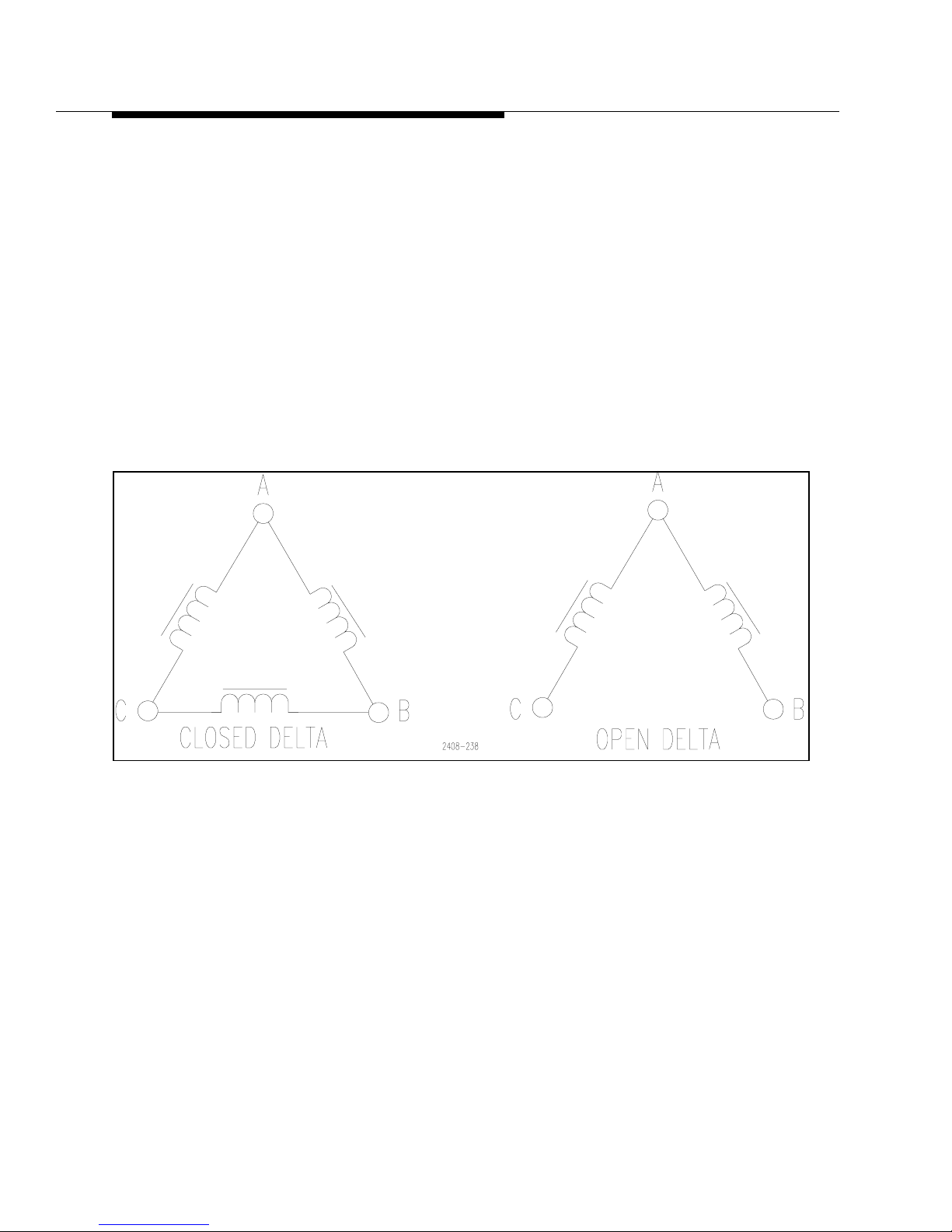
2-32 888-2408-002
WARNING: Discon nect primar y power prior to servicing.
Installation & Initial Turn-On
Another likely source of this problem can come from unbalanced impedances in the
power distribution system. Unbalanced impedance will always be seen when an
“open” delta three phase distribution system is used. Transformer design textbooks
clearly show that the voltage regulation of an unbalanced system is poor.
2.10.4 Three Phase Delta Distribution Transformers
Figure 2-19 shows open and closed delta systems. The closed delta impedance
looking into each terminal (A, B & C) is exactly the same; but this is not the case in
the open delta configuration. Depending on the impedances of the transformers in
the open delta circuit, line voltage unbalance sufficient to impair satisfactory
operation of the overall transmitter may result. For this reason, along with their
inherent susceptibility to transients, Harris does not recommend the use of open
delta systems.
Figure 2-19 Closed Delta vs. Open Delta
The only advantage of the open delta is lower initial cost, and this is partially offset
by the fact that when only two transformers are used, they must be larger than the
three transformers in a closed delta system.
Difficulties have often been experienced with open delta systems; but when a third
transformer was added to close the delta, the problems disappeared.
There is another problem which can occur with an open delta system, and that is
caused by lightning and switching transients. When lightning strikes or heavy loads
are switched on a power distribution system, high voltage transients are propagated
throughout the system. Unbalanced impedances will enhance these transients and
can cause transmitter damage, particularly to solid state rectifiers.
Page 53
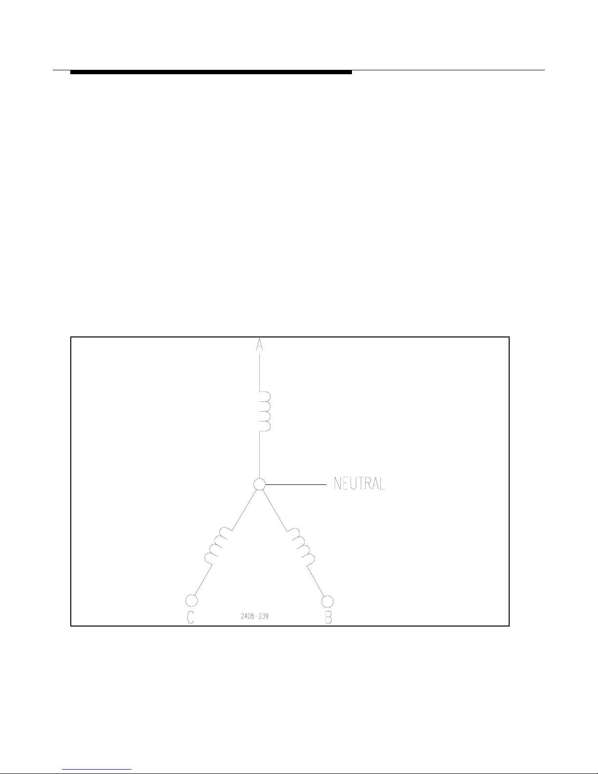
888-2408-002 2-33
WARNING: Discon nect primar y power prior t o servicing .
Installation & Initial Turn-On
Many transmitters are located at the end of a long transmission line which is highly
susceptible to transient phenomena. Devices such as Metal Oxide Varistors are
inexpensive and very effective in reducing over voltage spikes. These units are
limited in the amount of energy that can be dissipated, but will handle, if designed
properly, very large currents. You can’t take a direct lightning hit and still operate,
but not many things will. It has been reported by engineers that insta llation of a third
transformer and transient protection devices, have eliminated the difficulty.
2.10.5 Three Phase Wye Distribution Transformers
The WYE connected system is also considered a symmetrical form of three phase
power distribution. All impedances are balanced as seen from each terminal, see
Figure 2-20. It is important when using a WYE connected system that the fourth
wire (neutral) is connected to the mid-point of the system as shown in the diagram.
When this connection is made it provides a path for the zero sequence currents as
well as any harmonic currents which are generated due to the rectification of the
secondary voltages.
Figure 2-20 3-Phase 4-Wire WYE
Page 54

2-34 888-2408-002
WARNING: Discon nect primar y power prior to servicing.
Installation & Initial Turn-On
T oday, many transformers are supplied with all of the primary terminals a vailable so
that either a delta or WYE connection can be made. Table 2-3 shows the different
line-to-line voltages that are available with this configuration.
In summary, both symmetrical power distribution systems are satisfactory because
of their balanced impedances. Use either a closed delta or a four wire WYE system
for maximum transmitter performance. Never use an open delta system just to cut
costs - it could cost dearly in the long run.
Table 2-3 Typical Line Voltages, Delta or WYE
Delta Connected
Transformer
WYE Connected
Transformer
210 364
220* 380*
230 400
240* 415*
250 433
*Typical voltages in some areas of the world.
Page 55
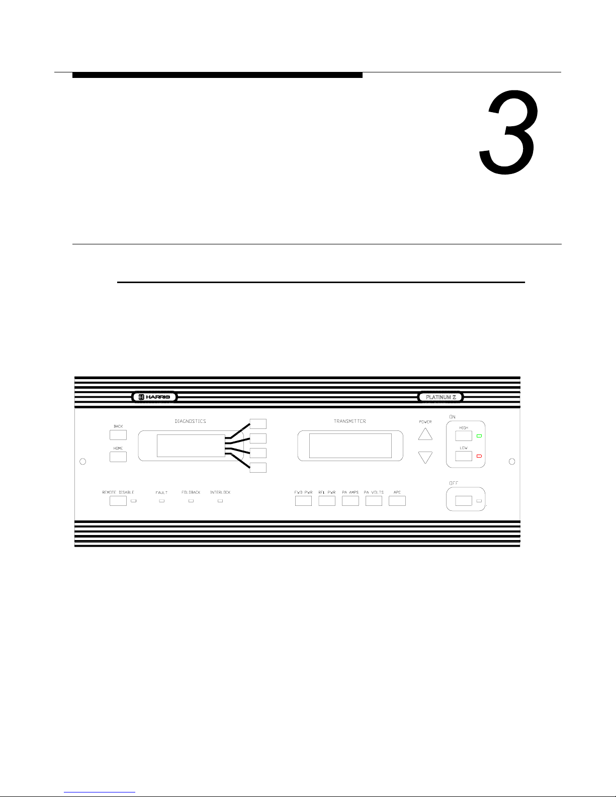
888-2408-002 3-1
WARNING: Disconnect primary power prior to servicing.
Operator Guide
3.1 Introduction
This section contains normal operational procedures and information pertaining to
the function of the Platinum Z5 Transmitter. Most important, is the information
regarding use of the Diagnostic System. All of the information in this section
assumes the the transmitter and controller are in proper working order.
Figure 3-1 Transmitter Controller Panel
Page 56

3-2 888-2408-002
WARNING: Discon nect primar y power prior to servicing.
Operator Guide
3.2 Transmitter Controls
The transmitter controls are mostly on the right half of the controller front panel at
the top of the transmitter, See Figure 3-1. These controls and their function are listed
below.
OFF - Used to turn the transmitter off
ON - HIGH - Turns the transmitter on to the previous HIGH setting. If the
transmitter has folded back power automatically, due for instance to high VSWR,
pressing the HIGH button will return the transmitter to the normal high power level
provided the cause of the foldback is gone.
ON - LOW - Turns the transmitter on to the previous LOW setting. If the transmitter
has folded back power automatically, due for instance to high VSWR, pressing the
LOW button will return the transmitter to the normal low power level provided the
cause of the foldback is gone.
POWER (up/down arrows) - used to raise and lower the transmitter power.
REMOTE DISABLE - (Located on the left side of the controller) used to disable
any remote control system which is connected to the transmitter. When the LED is
lit, the remote control inputs are disabled.
NOTE:
Some of the less often used transmitter controls, such as calibration and configuration, are located in the menu screens of the Diagnostics system. These
are covered as part of the Diagnostics system later in this section.
Page 57

888-2408-002 3-3
WARNING: Discon nect primar y power prior t o servicing .
Operator Guide
3.3 Transmitter Metering
There are five function keys below the Transmitter display on the front of the
controller:
1. FWD PWR (Forward Power)
2. RFL PWR (Reflected Power)
3. PA Amps
4. PA Volts
5. APC (Automatic Power Control)
These are dedicated metering selections for the 5 most important transmitter
parameters. The Diagnostic Display will provide all other necessary metering, while
still being able to monitor these five readings.
3.3.1 Forward Power (FWD PWR) Units of Measure
The default unit of measure for the forward power reading is percentage, with 100%
representing the nominal power output for the station. This percentage can be
calibrated to any power level using the Configuration controls in the Diagnostics
System. If desired, the forward power reading can be converted to kilowatt by
simply pressing and holding the FWD PWR button for at least 3 seconds. After 3
seconds the display should automatically change to power in kilowatts.
3.3.2 Reflected Power (RFL PWR) Units of Measure
The default unit of measure for reflected power is VSWR. If desired, the reflected
power reading can be converted to kilowatt by simply pressing and holding the RFL
PWR button for at least 3 seconds. After 3 seconds the display should automatically
change to power in kilowatts.
Page 58
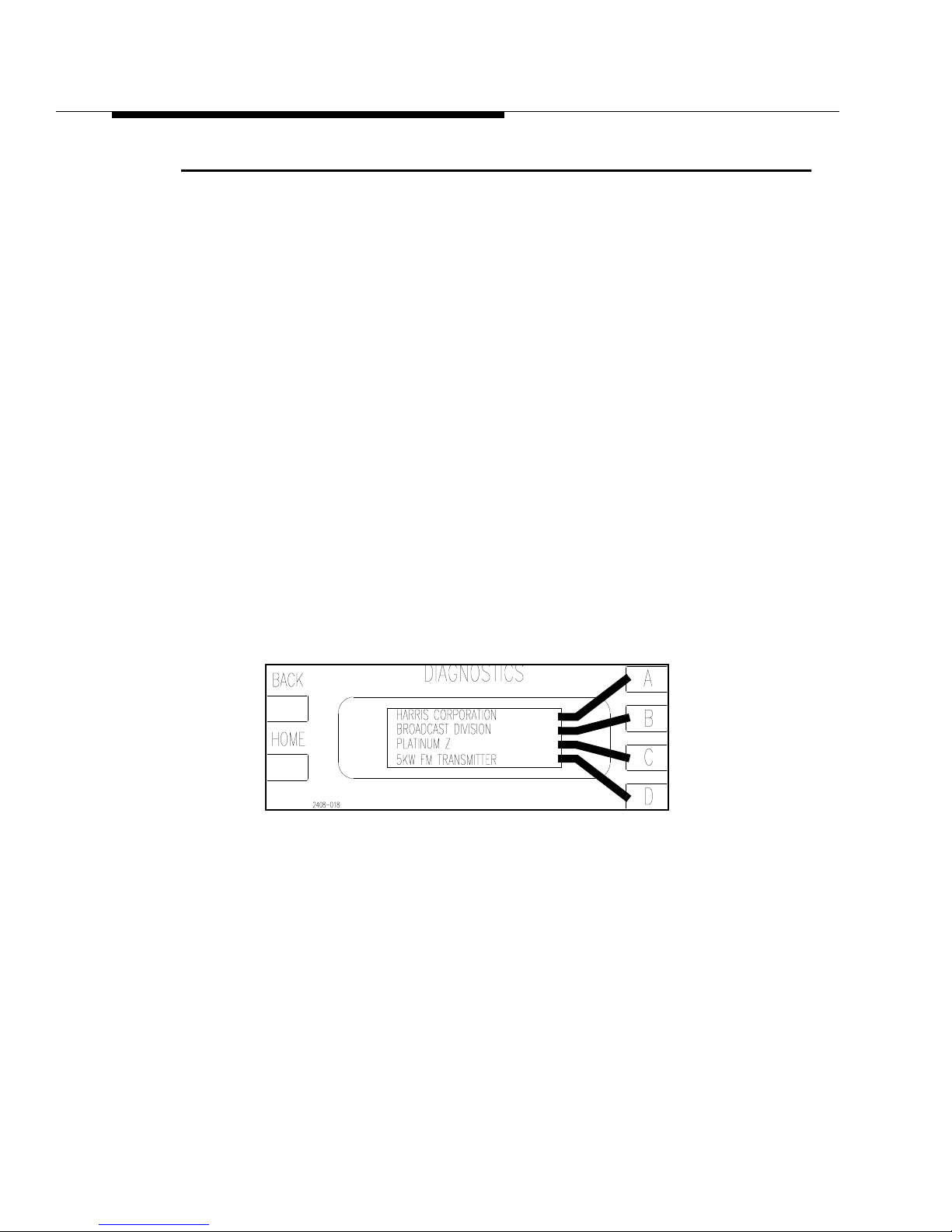
3-4 888-2408-002
WARNING: Discon nect primar y power prior to servicing.
Operator Guide
3.4 Using the Diagnostic Displa y
The Platinum Z Series transmitters utilizes a very unique and powerful diagnostic
system. The diagnostic system is actually your interface to the inner workings of the
transmitter. It is used for Status, Metering, Fault Logging, Configuration and even
hardware and software Testing of the controller. A good working knowledge of the
diagnostic system is crucial to proper transmitter maintenance and operation.
Familiarization with the display and its operation should be quick and easy. Simply
press the HOME key and follow the menus. A drawing labeled “Diagnostics
Display Menu Tree” is included in the schematic package. This drawing shows all
of the menus and screens available in the Diagnostic display system. Note that the
drawings are divided into layers from left to right, with Layer 1 considered the
HOME layer at the left and successive layers to the right.
The diagnostic system consists of the LCD Diagnostic display and 6 function keys,
HOME, BACK and the four selection keys on the right side of the LCD screen.
IMPORTANT: For all discussions pertaining to the Diagnostic system, the four
function keys to the right side of the Diagnostic LCD display will be called A, B, C
and D from top to bottom as in Figure 3-2. This figure also shows the default screen
which will show up when the controller is first turned on or after being idle for 15
minutes.
Figure 3-2 Default Diagnostics Screen
Page 59
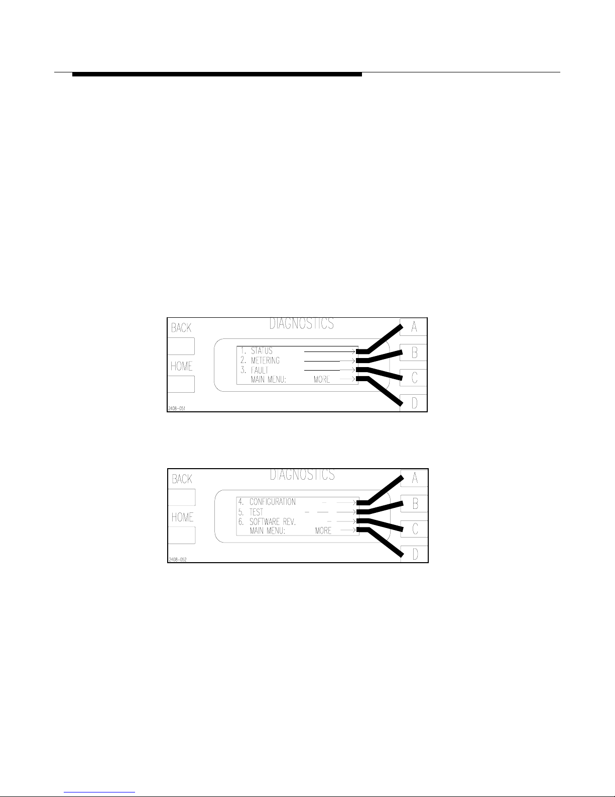
888-2408-002 3-5
WARNING: Discon nect primar y power prior t o servicing .
Operator Guide
3.4.1 HOME
HOME takes you to the home layer or root menu. This menu should look like the
one in Figure 3-3, which is the first of two screens in this layer. The second screen
in the HOME layer is accessed by pressing the “D” function key to the right of the
display which is labelled “MORE -” on the display . The screen should now look like
Figure 3-4. These two screens give access to all six HOME menus:
• Status
• Metering
• Fault
• Configuration
• Test
• Software Revision
Figure 3-3 Home Menu Page 1
Figure 3-4 Home Menu Page 2
Page 60

3-6 888-2408-002
WARNING: Discon nect primar y power prior to servicing.
Operator Guide
3.4.2 BACK
BACK takes you to the previous layer in the menu tree, not necessarily to the
previous screen. As an example, if you were to press HOME and then choose
STATUS you would now be in layer 2 of the STATUS menu. You should see the
screen shown in Figure 3-5. If you press MORE, you go the the second screen in
layer 2. Now press the BACK key. Notice that it did not take you to the previous
screen but back to Layer 1, the HOME layer, shown in Figure 3-3. However, if
instead of pressing BACK, you pressed more again, this would have taken you to
the first screen in layer 2 (since there are only two screens).
Figure 3-5 Status Layer 2, Page 1
3.4.3 MORE
MORE is a menu item which is used when there are more menu items on a layer
than will fit on one screen. It will take you to the next screen in the same layer.
When you have reached the last screen in that layer , pressing MOR E again will take
you back to the first screen in that layer. This is shown on the Diagnostics Display
Menu Tree drawings.
3.4.4 Diagnostic Codes
For ease of discussion a simple code will be used to guide you to the area or screen
being discussed. The code will have the name of one of the HOME menu items
listed above, followed by the appropriate A, B, C or D function key presses required
to get to the screen being discussed. The code will always be enclosed in brakets
[x,x,x].
NOTE:
It will be assumed that you always press the HOME key first before entering
the key sequences in the brackets.
Page 61
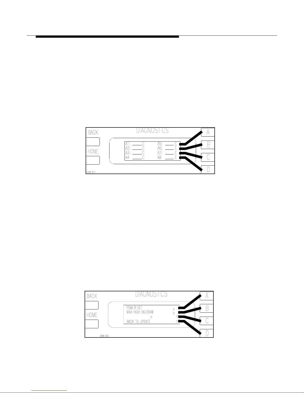
888-2408-002 3-7
WARNING: Discon nect primar y power prior t o servicing .
Operator Guide
Example 1
If you wanted to check the temperature of the individual Power Amplifiers on Z
Plane A, you would press the following keys;
[HOME, METERING C,A,C]
After entering this key sequence the screen should look like Figure 3-6. This is
equivalent to pressing the following menu items as they appear on each successive
screen: METERING, TEMPERATURE, PA, Z PLANE A.
Figure 3-6 PA Temperature Metering
[HOME, METERING C,A,C]
Example 2
You want to check or possibly change the Maximum High Power Setting. This falls
under the category of CONFIGURA TION, but this menu item only shows up on the
second screen of the HOME layer. Therefore, press the following keys:
[HOME, MORE, CONFIGURATION B,B]
This should have taken you to the screen shown in Figure 3-7. This screen now
allows the operator to change the Maximum High Power setting using the A,B,C
and D function keys. Pressing the BACK key updates the change, while pressing
HOME would cancel any changes.
Figure 3-7 Max High Power Configuration Screen
[HOME, MORE, CONFIGURATION B,B]
Page 62

3-8 888-2408-002
WARNING: Discon nect primar y power prior to servicing.
Operator Guide
3.4.5 Asterisk and Pound Signs(*, #)
The asterisk and the pound sign characters are used in some of the metering menus
of the Diagnostics Display. If an asterisk (*) shows up in a metering menu, it means
that there is no data being received for that reading. The pound sign will only be
used in the Vg (Gate Control Voltage for the individual PAs) menus and signifies
that there has been a crossover (this is a condition where one PA Controller crosses
over and mutes the PAs associated with another PA Controller).
3.4.6 Fault Logging
The Fault Log is located under “Fault” in the Main Menu. Pressing Fault will take
you to the screen shown in Figure 3-8. This screen gives you a choice of resetting
the transmitter faults and fault log (and clearing any red indicators) or viewing the
Fault Log. Pressing B then takes you to the Fault Log, shown in Figure 3-9. This
screen shows the latest of a possible 32 faults as designated by “LOG No. 1 of N”,
where N would be the total number of faults present. “Type” gives the name of the
fault. The individual faults and their cause are given in Section VI, Troubleshooting.
“Time” gives the elapsed time since the fault occurred, not the actual time at which
it occurred. “Status” tells you whether the fault is cleared or is still active. Pressing
the D or PREV button will take you to the previous fault in the display.
Figure 3-8 Fault Menu
HOME, FAULT
Figure 3-9 Fault Log
[HOME, FAULT D]
Page 63

888-2408-002 3-9
WARNING: Discon nect primar y power prior t o servicing .
Operator Guide
3.5 Emergency Operating Procedures
3.5.1 Multiple PA Failures in a Foursome
!
WARNING:
THE PA MODULES ARE DESIGNED TO HANDLE VERY HIGH TEMPERATURES
AND MAY BE EXTREMELY HOT. DO NOT TOUCH THE MODULES WITH BARE
HANDS AFTER THE TRANSMITTER HAS BEEN RUNNING, ESPECIALL Y IN HIGH
AMBIENT TEMPERATURE ENVIRONMENTS.
If two PAs were to fail in a single group of four or Foursome, the resulting system
imbalance could result in a power foldback to approximately 84% of nominal power
output. Since a single PA failure in a foursome does not create an imbalance severe
enough to cause foldback, one of the PA modules with a bad PA should be taken
out, turned over and re-inserted, placing the bad PA in a different foursome. For
example, if PA amplifiers B1 and B2 have failed, pull out the A2/B2 PA module,
turn it over and plug it back in so that the bad PA is in position A2 instead of B2.
There are still 2 failed PAs, B1 and A2, but now each one is in a different foursome.
This will restore balance to the system and the transmitter will still be able to
operate at or near full power output by automatically increasing the drive to the
remaining PAs (via the APC voltage). For more information on Foursomes refer to
Section IV, Overall System Theory, under the heading “8-Way Combiner”.
For quick reference, the foursome groupings are as follows:
(See Figure 4-5 and Figure 4-6 on page 4-12)
• A1, A2, A3 and A4 - Front Right Foursome
• B1, B2, B3 and B4 - Front Left Foursome
• A5, A6, A7 and A8 - Rear Left Foursome
• B5, B6, B7 and B8 - Rear Right Foursome
Page 64
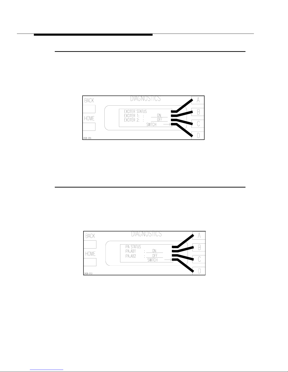
3-10 888-2408-002
WARNING: Discon nect primar y power prior to servicing.
Operator Guide
3.6 Manual Exciter Switching
The active exciter (if dual exciters are installe d) can be switc hed manually from the
Status menus in the Diagnostics Display. To manually switch from Exciter 1 to
Exciter 2 press [HOME, STATUS D,C]. This will bring up the screen shown in
Figure 3-10. Pressing [D] will toggle between the two exciters.
Figure 3-10 Exciter Status Screen
[HOME, STATUS D,C]
3.7 Manual IPA Switching
The active IPA can be switched manually from the Status menus in the Diagnostics
Display. To manually switch from IPA_AB1 to IPA_AB2 press [HOME, STATUS,
D,B].This will bring up the screen shown in Figure 3-11. Pressing [D] will toggle
between the two IPAs.
Figure 3-11 IPA Status Screen
[HOME, STATUS, D,B]
Page 65

888-2408-002 3-11
WARNING: Discon nect primar y power prior t o servicing .
Operator Guide
3.8 Optimizing Efficiency
The transmitter has the ability to Manually or Automatically optimize its own
operating efficiency. It is not a requirement, and the transmitter will meet all
specifications without activating this function. When activated, the controller will
adjust the transmitter operating parameters to get the best possible efficiency. The
user must select whether the function is in Manual or Automatic mode via the
Diagnostics Display Menus. To select the mode press [HOME, MORE,
CONFIGURATION A,D,D then A to toggle: ON for auto mode or OFF for Manual
mode]. The configuration screen is shown in Figure 3-12.
• Automatic Mode - When AUTO mode is selected, the transmitter will automati-
cally optimize the efficiency every 12 hours if there are not faults present. This is
the recommended mode of operation and is the default mode from the factory.
• Manual Mode - In the Diagnostics Display there is a menu screen which can be
used to optimize the transmitter ef fi cienc y. To optimize efficiency press [HOME,
METERING D,C then D for Maximization]. The Efficiency Status/Manual Optimize screen is shown in Figure 3-13.
NOTE:
The REF VOLTAGE in Figure 3-13 is merely an internal reference point the
controller uses to reduce the supply voltage in optimized mode. This reading
is usually in the low 40’s when the transmitter is optimized (well below the
actual supply voltage).
Figure 3-12 Efficiency Configuration Screen
[HOME, MORE, CONFIGURATION A,D,D]
Figure 3-13 Efficiency Status Screen
[HOME, METERING D,C]
Page 66
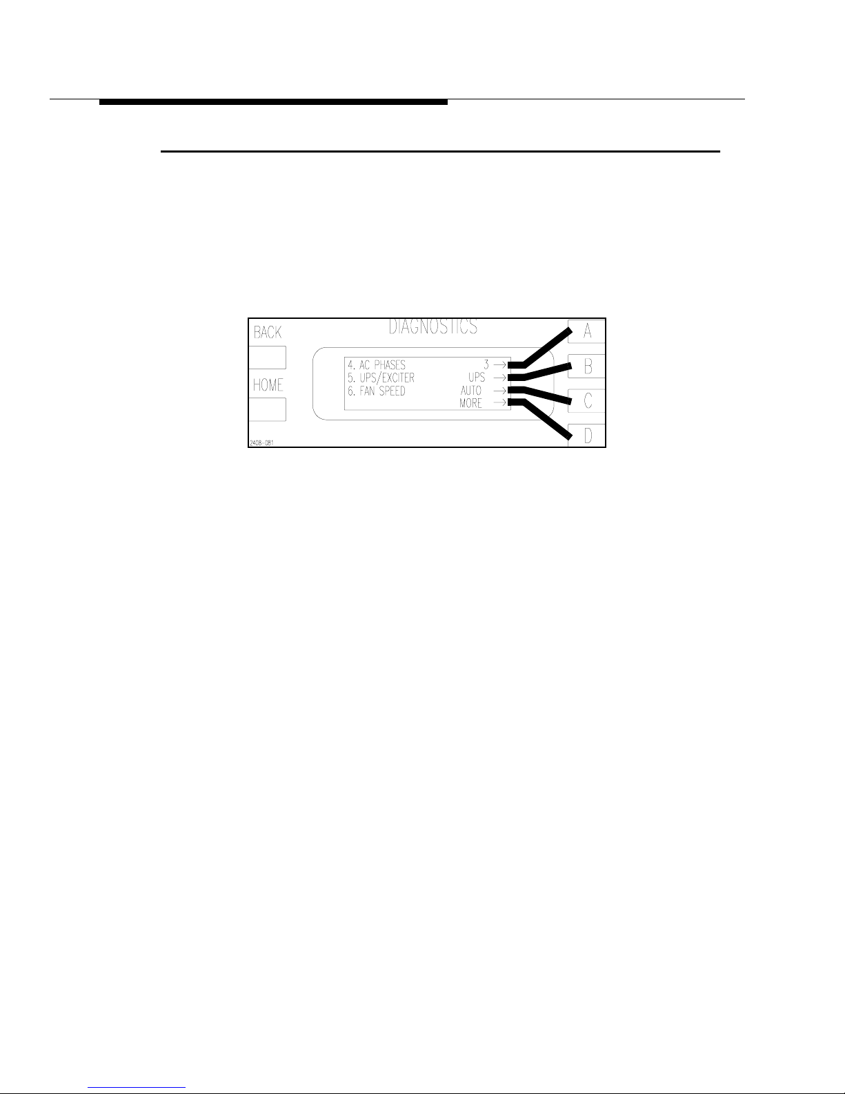
3-12 888-2408-002
WARNING: Discon nect primar y power prior to servicing.
Operator Guide
3.9 Fan Speed
The Platinum Z is equipped with a 2 speed blower. This normally runs at the LOW
speed to reduce ambient noise and increase transmitter efficiency. However, if any
fault occurs, the fan will automatically switch to high speed until the fault is no
longer active. The fan can also be forced to HIGH speed using the configuration
menus in the Diagnostics Display. See Figure 3-14. The normal setting for the fan
speed is AUTO. Pressing the [C] button toggles between AUTO and HIGH.
Figure 3-14 Efficiency Status Screen
[HOME, MORE, CONFIGURATION A,D]
Page 67

888-2408-002 4-1
WARNING: Disconnect primary power prior to servicing.
Overall System
Theory
4.1 Introduction
This section contains theory of operation and circuit descriptions of the Platinum
Z5™ FM Broadcast Transmitter.
The Platinum Z5™ has two possible designations:
• Z5CD, which is a 5kW FM transmitter supplied with the DIGIT, digital FM
exciter. CD stands for Clearly Digital.
• Z5FM which is a 5kW FM transmitter supplied with the SuperCiter, analog FM
exciter.
4.2 RF Flow Block Diagram Description
Figure 4-1 is a block diagram of RF flow of the Pl atinum Z5 transmitt er. Not shown
on this diagram is the control and monitoring associated with the advanced
Controller and Diagnostics system.
4.2.1 Exciters
It starts with the built in dual exciter option (in other words the switching
components are present but the exciter is optional). The RF output of both exciters
(if present) connect in to the Exciter/IPA Backplane board. The exciter RF switch
shown on this board is activated by the controller if Exciter A were to fail, placing
Exciter B on the air automatically. This fault and all other transmitter faults are
stored in the Fault Log in the Diagnostics Display Syst em. The active exciter output
is selected by the first RF switch and directed to the active IPA by the second RF
switch. Both RF switches are controlled by the Master Controller.
Page 68
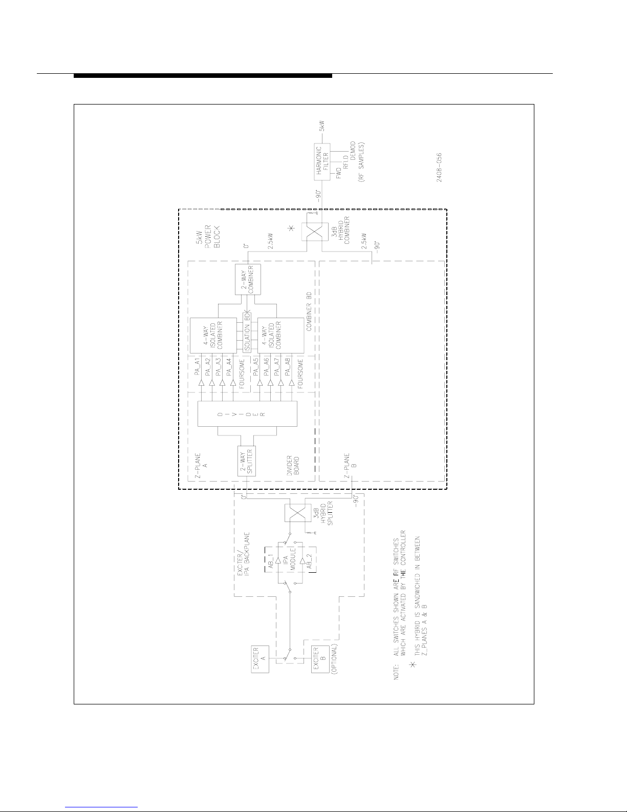
4-2 888-2408-002
WARNING: Discon nect primar y power prior to servicing.
Overall System Theory
Figure 4-1 RF System Block Diagram
Page 69

888-2408-002 4-3
WARNING: Discon nect primar y power prior t o servicing .
Overall System Theory
4.2.2 IPAs
The Z5 has 1 IPA Module, which is made up of 2 power amplifiers or PAs. The IPA
Module is identical to, and interchangeable with, the PA Modules. The 2 IPAs per
IPA Module operate in Main/Alternate mode, meaning that only one of them is
active at a time. The block diagram shows that IPA_AB1 is the normally active
amplifier. RF switching on the input and output of the IPA is activated by the
controller if a fault is sensed in the active IPA. The IPA output is split using a 3dB
hybrid built onto the IPA Backplane Board. This provides 2 equal amplitude outputs
90 degrees out of phase to drive the Power Amplifiers.
4.2.3 PA
The Z5 contains two Z-Planes which could be considered 2.5kW Power Blocks. For
simplicity in Figure 4-1, Z-Plane A is the only one which shows the actual
component assemblies located on each Z-Plane. Z-Plane B is identical. Next, each
Z-Plane can also be broken down into 2 parts, a Divider Board and a Combiner
Board.
4.2.3.1 Z-Plane Divider Board
The Divider Board takes the IPA input and uses a 2 way wilkinson splitter to drive
two more 4 way Wilkinson splitters. This provides the necessary 8 drive signal for
the 8 PAs connected to Z-Plane A. The PAs are labeled A1-A8 for Z-Plane A and
B1-B8 for Z-Plane B. PAs 1-4 on each Z-Plane are located in the front of the
transmitter , while 5-8 are located in the re ar of the transmitt er . Any four PAs labeled
1-4 are considered a FOURSOME, because they are connected to the same 4 Way
combiner. Any PAs labeled 5-8 are also considered a Foursome. Here is a list of the
4 different Foursomes in the Z5: (See Figure 4-5 and Figure 4-6)
• A1, A2, A3 and A4 - Front, Z-Plane A
• B1, B2, B3 and B4 - Front, Z-Plane B
• A5, A6, A7 and A8 - Rear, Z_Plane A
• B5, B6, B7 and B8 - Rear, Z-Plane B
4.2.3.2 Z-Plane Combiner Board
The Combiner Board receives the outputs from the 8 PAs and combines them in two
4 Way Isolated Wilkinson Combiners, whose outputs are then combined in a 2 way
Wilkinson combiner for a 2.5kW nominal output. Each PA is capable of delivering
up to 425 watts into a good load, but will be operating at approximately 325 watts
nominally for 5kW of combined transmitter output. The isolation loads for all 3
combiners are located on another board called the Isolation Board for better heat
dissipation and easier access. The Isolation boards are located on each side of the
Power Block. The Isolation Board also contains RF switches which can switch out a
faulty PA without causing a severe system imbalance, allowing greater redundancy.
Page 70

4-4 888-2408-002
WARNING: Discon nect primar y power prior to servicing.
Overall System Theory
This also allows the PA Modules to be HOT-PLUGGABLE, meaning that a PA
module may be removed while the transmitter is operating. Interlock pins on the
module connectors mute the PA modules before it switches out the unplugged
module.
4.2.4 5kW Hybrid Combiner
The 2.5kW outputs from Z-Plane A and Z-Plane B are combined in a 3dB Hybrid
which is specially fit in between the two Z-Planes. The 5kW output from the hybrid
passes through an aluminum box under the PA (in the Power Supply Compartment)
and connects to the transmission line Harmonic Filter at the top rear of this box. The
harmonic filter connects to the output flange on the top rear of the transmitter. The
Harmonic Filter has 3 directional couplers. One is for Forward Power, one is for
Reflected Power and the third is left available for on site use as a Demodulator or
analyzer sample. The couplers are designed for at least 30dB directivity.
4.3 Detailed RF Theory of Operation
The exciter theory is described in a separate technical manual included with the
transmitter . Each of the remaining RF sections of the transmitter are described in the
following paragraphs.
4.3.1 Exciter Operation
The exciter output is basically fixed and should not require adjustment. The exciter
power output is set using the controls on the front of the exciter and should be set to
the “Exciter Power” reading on the factory test data sheet for the transmitter. For
information on setting exciter power, refer to the exciter manual.
4.3.1.1 Automatic Exciter Switching
If a second or backup exciter is installed and the on air exciter fails, the controller
will automatically switch to the backup exciter and log the fault. Note that the
controller will wait 10 seconds for the on-air exciter to recover before switching to
the backup. If a backup exciter is added anytime after factory testing, the installer
must go into the Configuration Menus on the Diagnostic Display and set “ALT
EXCITER” to YES to let the controller know that the backup exciter exists. If this is
not done the controller will not auto switch.
4.3.1.2 Manual Exciter Switching
For dual exciter configurations, the on-air exciter can be selected manually using
the Diagnostics Display . The exciter select screen is located in the Status menus and
shown in Figure 4-2. For exact location, refer to the “Diagnostics Display Menu
Tree” drawing in the schematic package. Manual exciter switching can also be done
via the configurable remote input. See Table 2-1 on page 2-28 for more information
on this remote control input.
Page 71
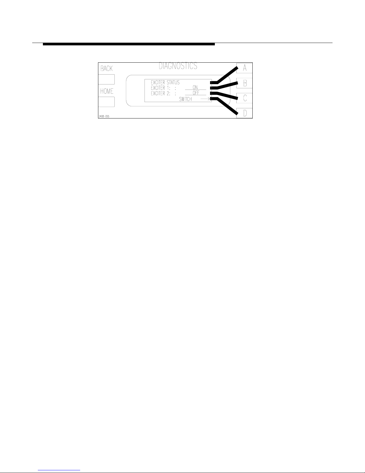
888-2408-002 4-5
WARNING: Discon nect primar y power prior t o servicing .
Overall System Theory
Figure 4-2 Exciter Status Screen
[HOME, STATUS D,C]
4.3.2 IPA
The IPA amplifier and/or module is identical to any one of the PA modules. This
allows a PA module to be used in place of a failed IPA. The standard IPA
configuration includes dual IPA amplifiers, used in a main/alternate configuration
(in other words only one is used at a time).In this configuration the IPA Module is
identical to a PA module. If one of the IPA amplifiers fails, the controller will
automatically switch to the second IPA with a minimal interruption of service. For a
detailed explanation of the RF amplifier operation refer to the paragraph “Power
Amplifier” later in this section.
4.3.2.1 IPA Power Output
The power output of the IPA determines the power output of the transmitter and is
varied by changing the gate bias on the IPA amplifiers MOSFETs. The gate bias for
the IPA is adjusted by the controller , specifically the Master Controller Board, using
the front panel “POWER” Raise and Lower controls.
4.3.2.2 IPA Power Supply
The IPA power supply is +52 volts and is diode or’ed from both of the PA power
supplies for redundancy. The +52Vdc is connected to the IPA(s) via the IPA
Backplane Board.
4.3.3 IPA Backplane Board
Refer to the IPA Backplane schematic for the following. The IPA module plugs into
the IPA Backplane Board. This board interfaces all inputs and outputs for the IPA
module. It is also responsible for:
• Main/Alternate exciter switching (only active with optional dual exciter configu-
ration).
• Main/Alternate IPA switching (active with standard, dual IPA configuration).
• Monitoring of IPA temperature, voltage, current and forward power.
Page 72
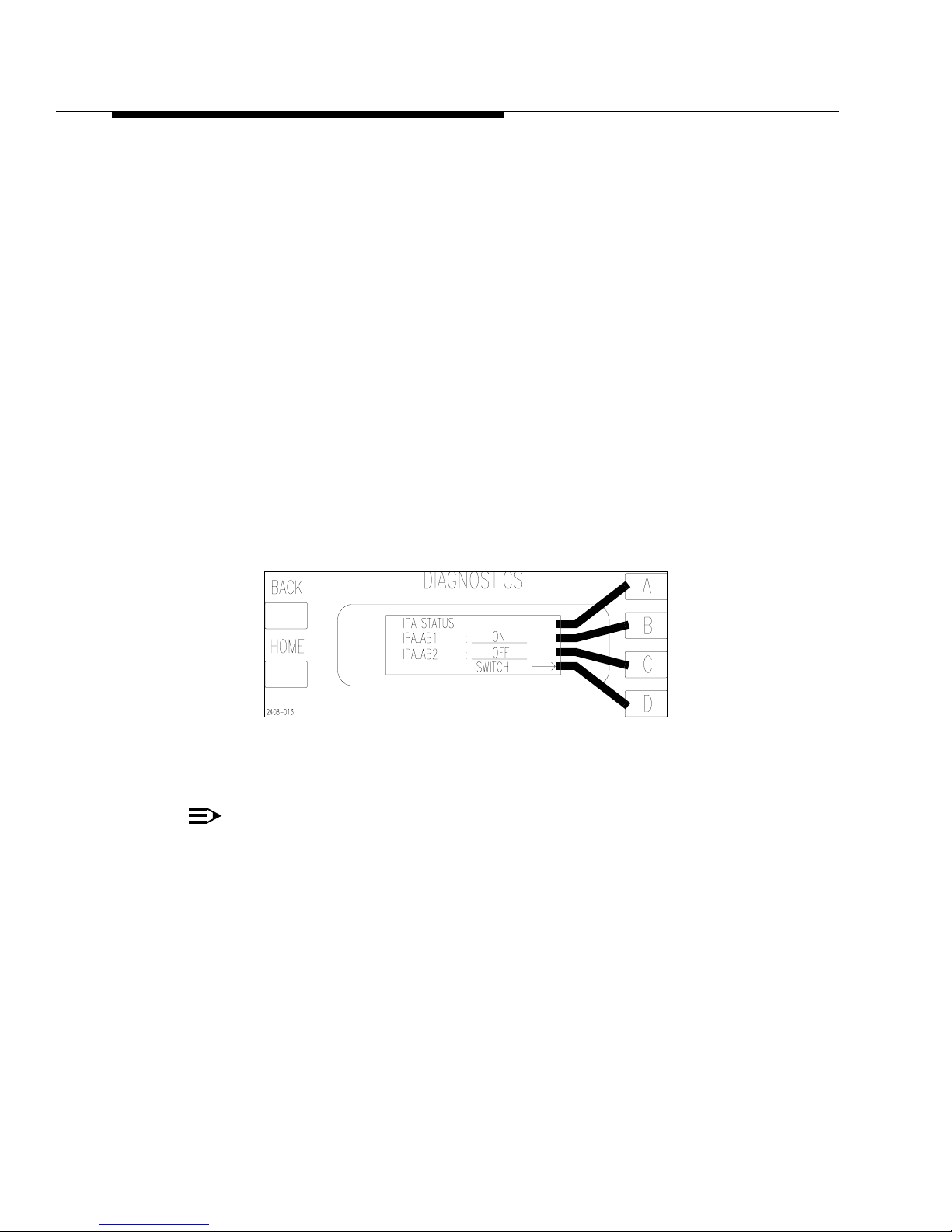
4-6 888-2408-002
WARNING: Discon nect primar y power prior to servicing.
Overall System Theory
• Splitting of the IPA output into 2 equal amplitude signals 90 degrees out of phase,
by way of a 3dB hybrid, to drive the Z Plane dividers.
• Air flow sensing
• Ambient temperature sensing
• IPA 1 and IPA 2 interlocking
4.3.3.1 Main/Alternate Exciter Switching
Exciter selection is done via relay K1 and the EXCITER SELECT control signal
from the Life Support Board. The EXCITER SELECT signal is normally low which
places K1 in the position shown on the schematic, sending the Exciter 1 RF output
to the IPA input relay K2. If EXCITER SELECT goes high, K1 will be energized
and switches to the Exciter 2 RF output. This switching will take place
automatically if an exciter fault is detected by the Master Controller board. Exciter
switching can also be done manually using the Diagnostics display. Press [HOME,
STATUS D,C] (this code is explained in Section III, Operation). This should bring
up the screen in Figure 4-2. Pressing the D function key will now toggle K1,
switching from exciter 1 to exciter 2 or vise versa.
Figure 4-3 IPA Status Screen
[HOME, STATUS D,B]
NOTE:
For easy navigation through the Diagnostic menus, refer to “Using the Diagnostic Display” in Section III, Operation and to the “Diagnostics Display
Menu Tree”, in the schematic package, which gives a complete overview of
the Diagnostics menu structure.
Page 73

888-2408-002 4-7
WARNING: Discon nect primar y power prior t o servicing .
Overall System Theory
4.3.3.2 Main/Alternate IPA Switching
Selection of IPA_AB1 or IPA_AB2 (both input and output) is done via relays K2,
K3 and the IPA DRIVER SELECT control signal from the Life Support Board.
NOTE:
The term “AB” is used to associate a component with Z-Plane A and Z-Plane B.
K2 switches the input RF drive from the exciter to IPA_AB1 or IP A_AB2 whi le K3
selects the active IPA RF output. The control signal, IPA DRIVER SELECT, is
normally low which places K2 and K3 in the IPA_AB1 position as shown on the
schematic. If IPA DRIVER SELECT goes high, K2 and K3 will be energized and
switch to the IP A_AB2 position. If the Master Controller detects a loss of RF output
from the active IPA it will automatically switch to the second IPA.
IPA switching can also be done manually using the Diagnostics display. Press
[HOME, STATUS, D,B] This should bring up the screen in Figure 4-3. Pressing the
D function key will now toggle K2 and K3, switching from IPA_AB1 to IPA_AB2
or vise versa.
4.3.3.3 IPA Monitoring
The IPA Backplane Board provides for monitoring and/or interfacing of 4 main IPA
parameters:
• IP A temperature (VTEMP_IPA1 and/or VTEMP_IP A2). If the IPA board exceeds
100°C, the controller will mute the transmitt er a nd/or switch to the alte rn ate IPA.
The sensor is actually located on the IPA board, but is interfaced through the
Backplane.
• IPA supply voltage (Vd_IPA_SAMPLE). A monitoring sample is sent to the con-
troller through fuse F2. The Supply voltage for the IPA is diode or’ed from both
PA supplies for redundancy.
• IPA current (Id_IPA). IPA current is measured by measuring the voltage drop
across the series resistor R1. IPA current fault threshold is set at 14.3 amps.
• IPA Forward Power (IPA FWD PWR). A sample of the IPA forward power is
taken by the directional coupler (shown right after K3 on the schematic) and
detected by CR1. The DC voltage at TP1 will therefore be relative to the IPA output. This is also sent to the controller for monitoring and main/alternate IPA
switching.
Page 74

4-8 888-2408-002
WARNING: Discon nect primar y power prior to servicing.
Overall System Theory
4.3.3.4 Air Flow Sensing.
Airflow is sensed as the difference in temperature between a heated sensor, RT1,
and an ambient sensor, RT2. R T1 is actively biased via R3 which will cause a steady
increase in temperature with no air flow. Under normal operation, the voltage
difference between the two sensor outputs will stabilize at some value depending on
the amount of air flow. If the airflow is reduced or non-existent, then RT1 will heat
up increasing its voltage output, whereas RT2 will stay the same. Eventually the
voltage difference between the two sensors will reach a threshold where the
controller will turn the fan to high speed to compensate for the reduced airflow. If
the airflow is still insufficient, the transmitter will be shut off.
4.3.3.5 IPA_AB1 and IPA_AB2 interlocking.
The signals IPA1_PCB_OK and IPA2_PCB_OK are the interlock signals for the
IPA boards. The interlock connections on the IPA board (and the PAs as well) are
shorter than the other pins. This causes the interlock connection to break before the
RF and voltage contacts when the module is unplugged. This gives the controller
time to shut off the IPAs (via the IPA gate voltage, IPA1_GATE) so that the
connector contacts do not arc.
4.3.3.6 IPA Power Divider (3dB Hybrid)
The IPA power divider is actually a 3dB hybrid which splits the IPA output into 2
equal amplitude signals 90 degrees out of phase to drive the Z Planes at J5 and J6.
Remember that the output of the Z Planes is recombined using another 3dB hybrid
which requires a relative 90 degree phase angle between the two input signals. The
reject port on the hybrid is connected to an external Reject Load. The hybrid
integrated onto the IPA Backplane Board.
4.3.4 Z-Plane Combiner/Divider Boards
There are two Z-Plane Combiner/Divider Boards in the Z5 transmitter. These two
boards provide all inputs to and outputs from the PA modules. The Z Plane is the
overall term for the combination of the Combiner and Divider boards. There is a
separate schematic for each part of the Z Plane in the schematic package. The first
page of each schematic is identical and is a block diagram of the entire Z Plane.
Each Z-Plane assembly contains:
• Edge connectors for 8 PA amplifier boards (4 in front and 4 in the rear). These
connectors are labeled J1-J8.
• An 8 way Wilkinson Divider, driven by the IPA, which feeds RF drive to each of
the 8 PA amplifiers.
• An 8 way Wilkinson Combiner which combines the output of the same 8 PA
amplifiers.
Page 75

888-2408-002 4-9
WARNING: Discon nect primar y power prior t o servicing .
Overall System Theory
The RF output of the Z-Plane board connects directly to the 3dB hybrid where it is
combined with the output of the second Z-Plane Combiner/Divider board. The Z
plane boards are identical, but the outputs connect to opposite ends of the 3dB
hybrid (one at the top and one at the bottom). This requires that one of the Z Planes
be physically inverted.
4.3.4.1 8-Way Divider
Refer to the Divider schematic for the following. Each 8-Way Divider is a 2-stage
Wilkinson divider. The 8 way dividers are located on the Z-plane boards in the
center of the PA assembly.
The input to the divider is first divided into two equal outputs at approximately 35
ohms by a two-way Wilkinson divider with a 70.7 ohm isolation resistor, R9. Each
of these outputs (each end of R9) is then divided into 4 outputs in a 4-way
Wilkinson divider.
The Wilkinson dividers contain terminating resistors which dissipate no power
when all of the outputs are correctly loaded, but if a PA is removed, resulting in an
open-circuit on an output, the Wilkinson circuit and the load resistors act to keep the
input impedance of the splitter near the nominal value of 50 ohms. Each output from
each 8-Way Divider is fed to the input of one PA Amplifier boards, at J1 - J8.
4.3.4.2 8-Way Combiner
Refer to the Combiner schematic for the following. Each 8-way combiner consists
of two 4-way Wilkinson combiners, called FOURSOMES, followed by a 2-way
Wilkinson combiner which combines the outputs of the two Foursomes. The
Foursomes are split up as follows:
• A1, A2, A3 and A4 - Front Right Foursome
• B1, B2, B3 and B4 - Front Left Foursome
• A5, A6, A7 and A8 - Rear Left Foursome
• B5, B6, B7 and B8 - Rear Right Foursome
The Wilkinson combiners include isolation loads (ISO loads) which dissipate no
power if all PA outputs are equal and in phase. These resistors are located on the
Isolation Boards and labeled RT1-RT8. The ISO resistors connect to the points
labeled E1-E8 on the Combiner schematic. If any input is lost due to failure of a PA
module, the associated ISO load will dissipate some power; approximately 150
watts, until the RF switch on the Isolation board disconnects the ISO load and
grounds that point (E1-E8) on the combiner. This now looks like an open to the 4way combiner output at E9 or E10 (the input to the 2-way combiner).
Page 76
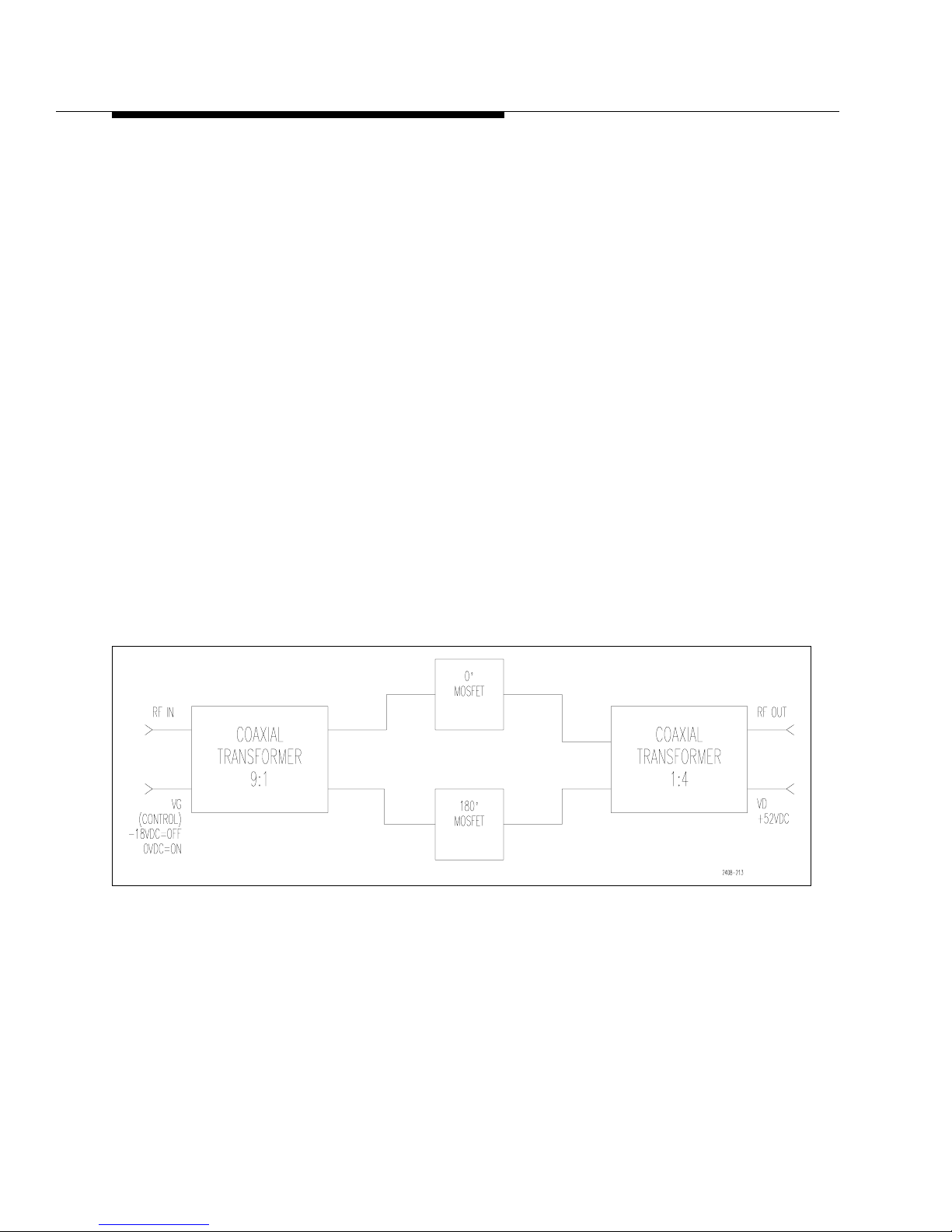
4-10 888-2408-002
WARNING: Discon nect primar y power prior to servicing.
Overall System Theory
4.3.4.3 PA Modules
Each of the 8 PA Modules contain two PA Amplifier boards mounted on opposite
sides of the PA Module heat sink. The modules are numbered 1 through 8 with the
top module in the front being #1 and counting to #4 at the bottom. The top rear
module is #5 counting down to #8 at the bottom rear, see Figure 4-5 for the front
view and Figure 4-6 for the rear view. The PAs are numbered as 1A, 1B, 8A, 8B
etc... with the “A” side PAs being plugged into the “A” Z Plane, and the “B” PAs
plugged into the “B” Z Plane. From the front of the transmitter, the “A” Z Plane is
on the right and the “B” Z Plane is on the left. Keep in mind this is reversed when
viewing from the rear of the transmitter. All DC, si gnal and RF connections to a PA
board are through one edge connector.
4.3.4.4 Power Amplifier (PA)
See Figure 4-4. The RF drive from the IPA enters the PA Amplifier Boards at Pin C.
The RF input level for each amplifier is typically 15-20 watts. TL1, C1 and C2
allow the input impedance to be matched to 50 ohms and permit the phase shift
through the module to be trimmed to a nominal value which allows all modules to
combine in-phase. The RF signal is the n sent to T1, a coaxial 9:1 transfo rmer which
also splits the phase providing 0 degree and 180 degree outputs to drive a pair of
push-pull RF power MOSFETs (Q1 and Q2). Bias to Q1 and Q2 (labeled VG for
Gate Voltage) is connected through the center of the secondary winding of T1.
Figure 4-4 Power Amplifier Block Diagram
The control voltage input called VG can be thought of as a bias voltage which can
be used to vary the amplifier output. Normally for the PAs it is simply used to turn
the amplifiers on and off. If VG is -18V the amplifier is off or muted. If VG is 0V
the amplifier is fully turned on and drive level from the IPA determines the
amplifier power output.
Page 77

888-2408-002 4-11
WARNING: Discon nect primar y power prior t o servicing .
Overall System Theory
When the amplifier is used as the IPA, VG is used to linearly vary the IPA output
which then controls the transmitter power output. For an IPA, VG comes from the
Life Support Board and is controlled by the APC loop on the Master Controller
Board. Pressing the RAISE and LOWER controls on the front of the transmitter will
vary the APC voltage which in turn will vary VG to the IPAs. This will vary the IPA
RF output, which will raise or lower transmitter power.
The MOSFET outputs are combined in T2, a 1:4 transformer. C19 and C20 finematch the 50 ohm load impedance at the PA output to the output impedance of T2.
The +52Vdc or VD (Drain Voltage) from the main power supply enters at location
C-1 and is decoupled and filtered by C11, C12, C13, C14, C16, C24, L1 and L2.
The DC voltage reaches the drain of MOSFETs Q1 and Q2 through the center tap of
T2’s primary winding. The advantage of this method is to allow direct DC
connection to the MOSFETs and have an AC RF output through the coax without
the need for a blocking capacitor.
Maximum RF output is 425 watts. Typical output level is 300 to 340 watts. The
power module is designed for single amplifier field replacement. In the event an RF
power MOSFET fails, field replacement is not practical due to the cost of
components, time and test equipment involved in repair and alignment of phase,
gain and response. This is a highly critical area, and if not done correctly, improper
module and transmitter operation will occur.
As an additional consideration, please observe the following warning from the
MOSFET manufacturer regarding beryllium oxide.
!
WARNING:
PRODUCT AND ENVIRONMENTAL SAFETY-T OXIC MA TERIALS. THIS PRODUCT
CONTAINS BERYLLIUM OXIDE. THE PRODUCT IS ENTIRELY SAFE PROVIDED
THA T THE BEO DISC IS NOT DAMAGED. ALL PERSONS WHO HANDLE, USE OR
DISPOSE OF THIS PRODUCT SHOULD BE AWARE OF ITS NATURE AND OF
THE NECESSARY SAFETY PRECAUTIONS. AFTER USE, DISPOSE OF AS
CHEMICAL OR SPECIAL WASTE ACCORDING TO THE REGULATIONS APPLYING A T THE LOCA TION OF THE USER. IT MUST NEVER BE THROWN OUT WITH
THE GENERAL OR DOMESTIC WASTE.
Failed PA boards should be sent in for repair or exchanged mainly due to the
minimal cost involved. Refer to the Maintenance section of this manual for the RF
amplifier replacement procedure.
Page 78
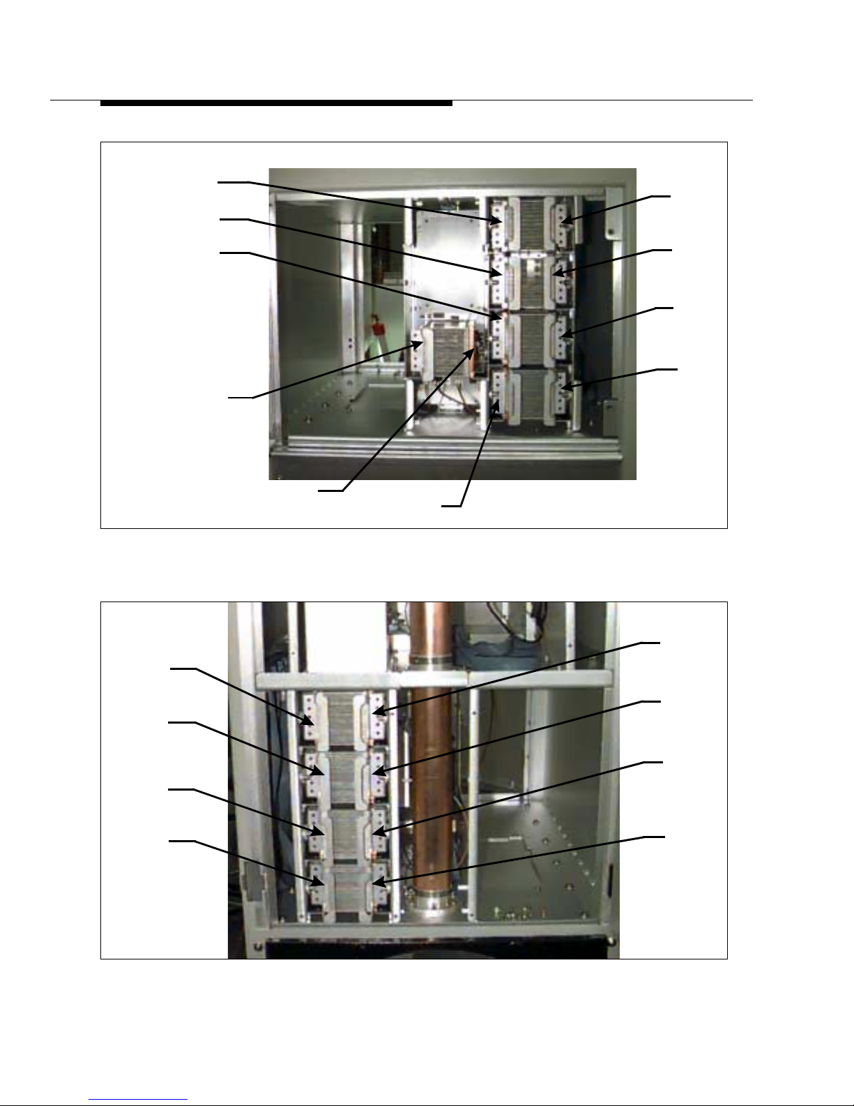
4-12 888-2408-002
WARNING: Discon nect primar y power prior to servicing.
Overall System Theory
Figure 4-5 PA Compartment Front View
Figure 4-6 PA Compartment Rear View
A1
A2
A3
A4
IPA_AB1
IPA_AB2
B1
B2
B3
B4
B5
B6
B7
B8
A5
A6
A7
A8
Page 79

888-2408-002 4-13
WARNING: Discon nect primar y power prior t o servicing .
Overall System Theory
4.3.4.4.1 Isolation Boards
Each Z Plane has an associated Isolation Board which contains the isolation
resistors and disconnect switches for the two 4-way wilkinson combiners and the
isolation resistor for the 2-way Wilkinson combiner. The isolation resistors for the
four way combiners, R1-R8, are each 50 ohm. When all modules are working
properly, these resistors dissipate little or no power. However, when a PA fails
approximately half of the power of one module will be across the isolation resistor.
The resistors will handle the imbalance of a failed module for about 20 seconds.
Therefore when a module has failed, the isolation resistor will start to heat up. This
rise in temperature is detected by a thermistor, RT1-RT8, which is physically
attached to the resistor . The thermistor is monitored by the associated PA Controller
Board (there are two). The PA Controller then shuts off the module RF output via
the PA gate voltage and activates the associated RF switch on the isolation board.
The switch disconnects the isolation resistor from the combiner and grounds output
of the PA (E1-E8). The entire Z Plane will be operating with a slight impedance
mismatch (it is now a 3-way combiner instead of a 4-way) but is well within the
ratings of the modules. The effects are minimized by the 2 way combiner and its
isolation resistor, which will tend to absorb imbalances, and by the characteristics of
the 3dB hybrid combiner, which tends to ignore minor amplitude and phase
imbalances in the two Z Plane outputs.
4.3.4.5 3 dB Hybrid Combiner
The 3dB combiner is located in the middle of the Power Block, between the two Z
Planes. The two outputs from the Z Planes are summed in the 3dB output combiner.
Since the RF inputs to the two Z Planes, driving the PA inputs, come from the 3dB
hybrid splitter on the IPA Backplane Board, they differ in phase by 90 degrees.
Thus, the outputs from the Z Planes differ by 90 degrees, allowing them to be
combined in the 3dB hybrid output port with very little power appearing at the
reject load.
If the two Z Plane outputs are not equal, or are not exactly 90 degrees apart in phase,
a portion of the power appears to the reject load, however the 3dB hybrid is a very
stable device which sends most of the input power to the combined output over a
fairly wide range of input power ratios and input phase differences. The reject load
is a 50 ohm 800 watt resistor mounted on a heatsink which is located on the upper
end of the hybrid, just above the Z-Planes. The output of the 3dB hybrid is on the
lower end of the hybrid and is connected to the transmission line Harmonic Filter in
the rear of the cabinet, via the aluminum enclosure just above the power supply.
There is a static drain choke located inside this box.
Page 80

4-14 888-2408-002
WARNING: Discon nect primar y power prior to servicing.
Overall System Theory
4.3.5 Harmonic Filter
The vertical transmission line a t t he re ar of the ca binet conta ins the Ha rm onic Filte r.
4.3.6 Directional Coupler Assembly
The directional coupler assembly is installed directly before the output from the
transmitter . It consists of 3 directional couplers with two of the couplers adjusted to
produce a sample of the forward output power, and one coupler arranged to provide
a sample of the reflected output power. The isolation, or directivity, of the couplers
is better than 30dB, with 40dB typical.
NOTE:
Note that the reflected coupler cannot be interchanged with the other 2 couplers due to the different coupling ratio for the forward and reflected samples.
The typical coupling ratio for each of the couplers is given below:
Forward Coupler - 48.8dB @ 88MHz to 47dB @ 108MHz
Reflected Coupler - 43.8dB @ 88MHz to 42dB @ 108MHz
(Typical tolerance is +/- 0.1dB but this is not guaranteed since any minor variation
can be factored out using the calibration procedures).
Page 81
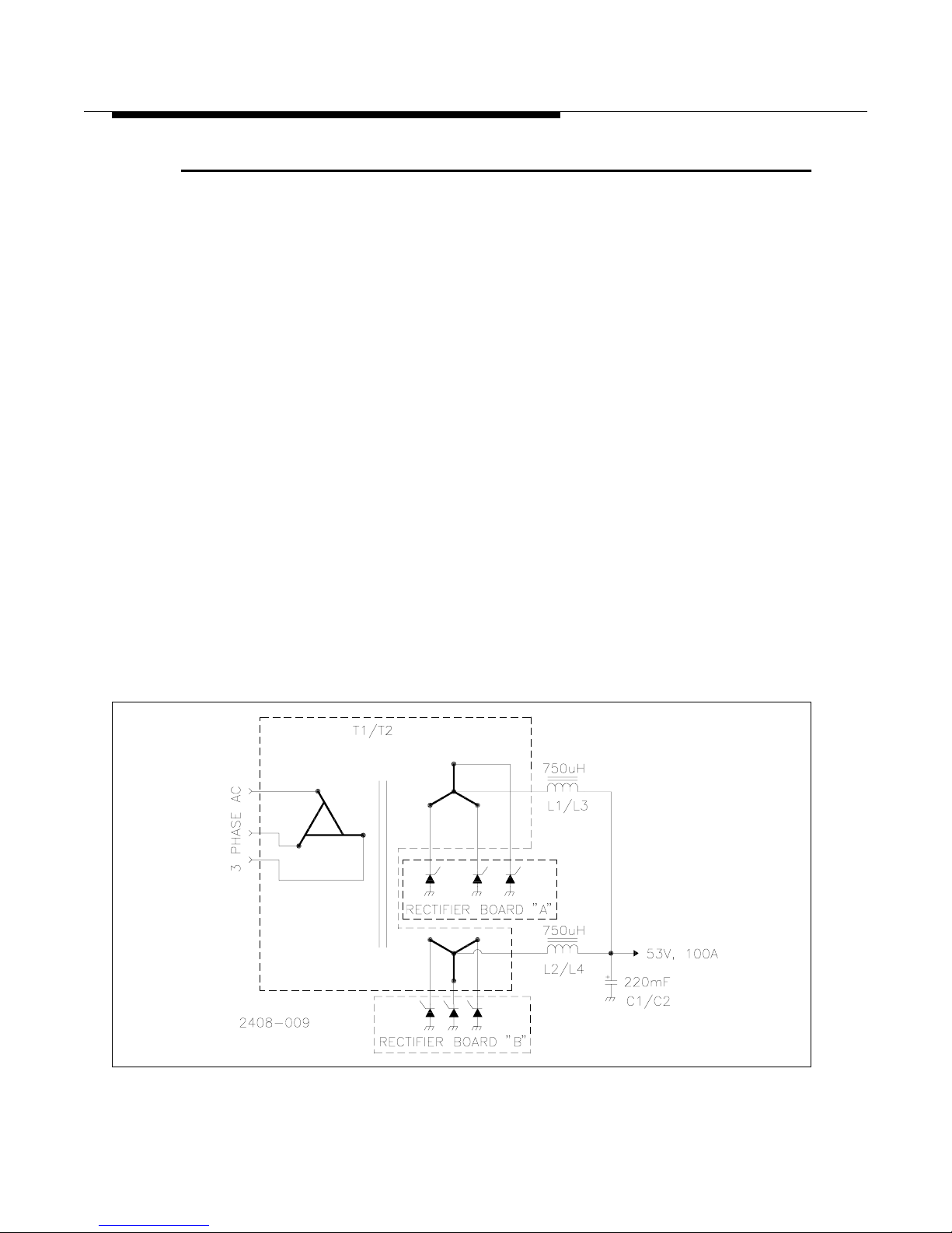
888-2408-002 4-15
WARNING: Discon nect primar y power prior t o servicing .
Overall System Theory
4.4 Power Supply Block Diagram Description
There are two different types of power supplies in the transmitter, the PA Power
Supply and the Low Voltage Power Supply.
4.4.1 PA Power Supply
There are three power supply configurations available for the Z5 transmitter:
• 3-Phase, 3 wire (198-250VAC)
• 3-Phase, 4 wire (342-432VAC)
• Single Phase (198-250VAC)
The supplies are very much alike operationally. The 3-Phase 3 wire and 4 wire
supplies have all of the same components, but have a different wiring harness. The
PA power supplies, whether 3-Phase or Single Phase, are regulated by reliable tap
switching techniques which provides excellent efficiency, while avoiding the power
line harmonic problems associated with switching supplies. The regulation range is
48-54Vdc at 2Vdc per tap.
4.4.1.1 3-Phase Power Supply
The Z5 transmitter uses dual main power transformers whose DC outputs are
combined through large inductive chokes. Figure 4-7 shows a simplified diagram of
one of the PA power supply transformers.
Figure 4-7 3-Phase Power Supply Simplified Diagram (1 Transformer)
Page 82

4-16 888-2408-002
WARNING: Discon nect primar y power prior to servicing.
Overall System Theory
Each transformer has a 3 wire extended DELTA or extended WYE primary
(depending on your AC input configuration) and two secondaries labeled A and B
which are always WYE wound, with the center tap being the output. The outputs of
the 2 secondaries are combined through chokes and filtered by a single 120,000uF
capacitor. The combination of the extended primary windings and the dual
secondaries (each at a different phase angle) results in an output ripple frequency of
600/720Hz for 50/60Hz input. Each of the secondary windings has 4 output taps,
each of which are connected through an SCR to ground. The SCRs act as both tap
switches, activating the tap which gives the appropriate DC voltage output, and as
rectifiers. This gives a total of 12 SCRs per secondary, but only 3 SCRs will be
activated at any one time providing the ability to regulate the output DC voltage by
changing the transformer turns ratio. The 4 secondary taps basically change the
primary to secondary turns ratio allowing allow DC outputs of 48, 50, 52 and
54Vdc. The tap switching is controlled by the Power Supply Controller board. The
two transformer assemblies are designated PS1 and PS2. PS1 provides power for 8
of the 16 P A s. Four of these are on Z Plane A and four on Z Plane B. Therefore PS 2
provides power for the remaining 8 PAs. There is only one PS Controller for both
supplies, however each supply still operates independently. Also each Power Supply
is connected to the same PAs as its corresponding PA Controller.
PS1 and PAC1 connect to A1, A2, A5, A6, B3, B4, B7 and B8.
PS2 and PAC2 connect to A3, A4, A7, A8, B1, B2, B5 and B6.
This information is also shown in Table 4-1 on page 4-60.
4.4.1.1.1 Soft Start
During transmitter turn on, a fifth set of SCRs is activated. See Figure 4-8. These
are connected to the lowest voltage output tap of transformer secondary “B” (the
one with the fewest secondary turns). However, the Soft Start SCRs are connected
through a common surge limiting resistor to ground, instead of the direct ground
connection provided with the rest of the SCRs. This allows the “Soft start” by
limiting the maximum surge current while charging the power supplies. The soft
start lasts for about two seconds during turn on. After the two second soft start the
resistor is bypassed by activating the normal run-mode SCRs which are also
attached to the lowest voltage output tap but connect directly to ground. This allows
the supplies to come up to full charge. If the voltage is not high enough, the Power
Supply Controller will activate the next highest tap to increase the voltage. It will
continue this process until the DC output voltage is approximately 52Vdc or it
reaches the highest tap.
Page 83
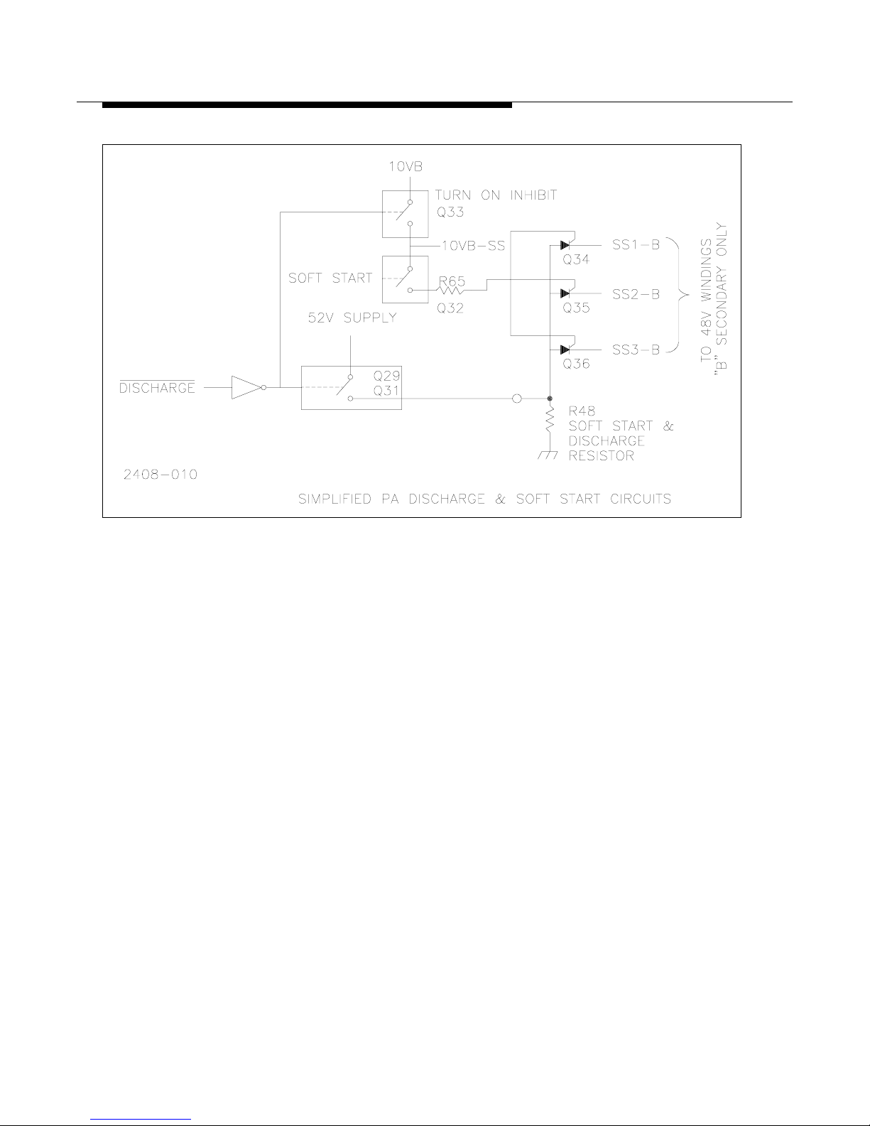
888-2408-002 4-17
WARNING: Discon nect primar y power prior t o servicing .
Overall System Theory
Figure 4-8 3-Phase Power Supply
Simplified Soft-Start and Discharge Circuit
4.4.1.1.1 PA Power Supply Discharge
The PA Power Supply Dischar ge circuit also uses the Soft Start resistor to discharge
the 52Vdc PA supply. The discharge circuit is activated when the transmitter is
turned off. When the discharge circuit is active, it disables the SCRs to prevent the
supply from trying to turn on during a discharge cycle.
Page 84
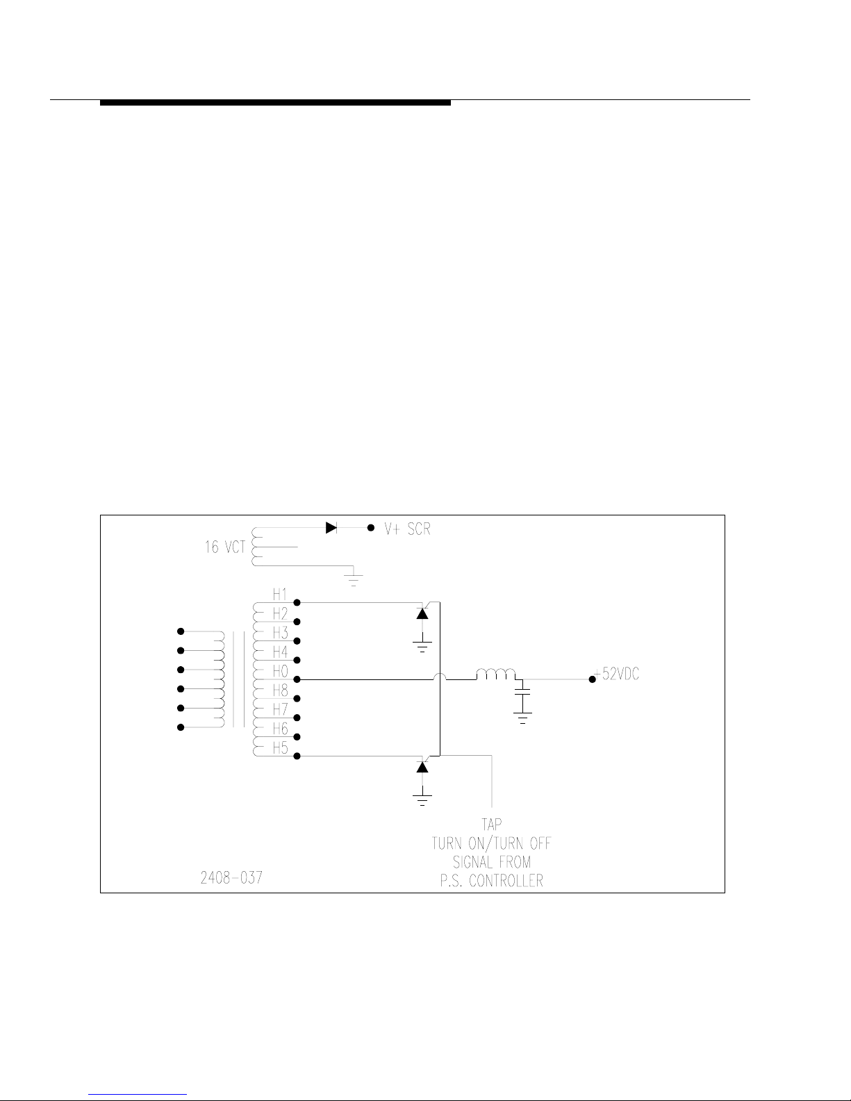
4-18 888-2408-002
WARNING: Discon nect primar y power prior to servicing.
Overall System Theory
4.4.1.2 Single Phase Power Supply
Refer to the Overall System Block Diagram in the schematic package and Figure 49 for the following discussion. The power supply consists of two power
transformers each with a single center tapped secondary. The center tap is the
52Vdc output and is filtered by a large choke and 3 large filter capacitors. The
single phase supply is full wave rectified giving a ripple frequency of 120Hz and
therefore requires more filtering than the 3-Phase supply.
Each of the secondary windings has 4 output taps, each of which are connected
through an SCR to ground. The SCRs act as both tap switches, activating the tap
which gives the appropriate DC voltage output, and as rectifiers. This gives a total
of 8 SCRs per secondary, only 2 of which will be activated at any one time
providing the ability to regulate the output DC voltage by changing the transformer
turns ratio. The 4 secondary taps allow DC outputs of 48, 50, 52 and 54Vdc. The tap
switching is controlled by the Power Supply Controller board. The two transformer
assemblies are designated PS1 and PS2. PS1 provides power for 8 of the 16 PAs.
Four of these are on Z Plane A and four on Z Plane B. Therefore PS 2 provides
power for the remaining 8 PAs.
Figure 4-9 Single Phase Power Supply
Simplified Diagram
Page 85
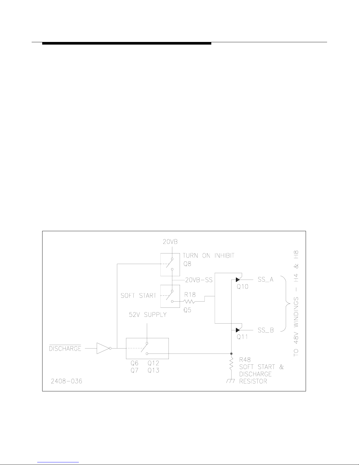
888-2408-002 4-19
WARNING: Discon nect primar y power prior t o servicing .
Overall System Theory
4.4.1.2.1 Soft Start
During transmitter turn on, a fifth set of SCRs is activated (these are located on the
Rectifier Boards). See Figure 4-10. These SCRs are connected to the lowest voltage
output tap of each transformer secondary (the one with the fewest secondary turns).
However, the Soft Start SCRs are connected through a common surge limiting
resistor to ground, instead of the direct ground connection provided with the rest of
the SCRs. This allows the “Soft start” by limiting the maximum surge c urrent while
charging the power supplies. The soft start lasts for about 6 seconds during turn on.
After the 6 second soft start the resistor is bypassed by activating the normal runmode SCRs which are also attached to the lowest voltage output tap but connect
directly to ground. This allows the supplies to come up to full charge. If the voltage
is not high enough, the Power Supply C ontroller will acti vate the next highest tap to
increase the voltage. It will continue this process until the DC output voltage is
approximately 52Vdc or it reaches the highest tap.
4.4.1.2.2 PA Power Supply Discharge
The PA Power Supply Dischar ge circuit also uses the Soft Start resistor to discharge
the 52Vdc PA supply. The discharge circuit is activated when the transmitter is
turned off. When the discharge circuit is active, it disables the SCRs to prevent the
supply from trying to turn on during a discharge cycle.
Figure 4-10 Single Phase Power Supply
Simplified Soft Start and Discharge Circuit
Page 86

4-20 888-2408-002
WARNING: Discon nect primar y power prior to servicing.
Overall System Theory
4.4.2 Low Voltage Power Supply
The Low Voltage Power Supply is a single PC board mounted in the rear of the
transmitter near the main contactor. It is designated A19 (assembly 19). The circuit
board is the same for the 3-Phase and single phase configurations, only the wiring to
and from the board is changed. It supplies DC voltages to all circuits in the
transmitter. These include:
• +20VDC
• -20VDC
• +10VDC
These voltages are sent to the Rectifier boards and then on to the controller boards.
The board contains 3 relays, A19K1, A19K2 and A19K3. When the transmitter is
turned on, A19K1 activates the main contactor (simply called K1) which then
applies AC to the PA power Supplies, while A19K2 applies AC to turn on the
exciter(s). A19K3 selects the low or high fan speed by actuating the fan speed select
relay K2 which is mounted near the main AC contactor.
4.5 Detailed Power Supply Descriptions
4.5.1 3-Phase PA Power Supply
Refer to the Overall System Block Diagram in the schematic package for the
following discussion. The transmitter 3 phase AC inputs connect directl y to K1, the
AC mains contactor. The transformer side of the contactor is wired in parallel to
power transformers T1 and T2 primaries in the bottom of the transm itter. T1 and T2
primaries must be tapped for the proper AC input voltage. The tapping chart can be
found on the Overall System Block Diagram. T1 and T2 can accommodate input
voltages in the range of 198 to 250 Vac.
Each transformer has 2, four wire WYE, secondaries with the center connection
being the rectified DC output of 52Vdc. The two secondary outputs are combined
via L1 and L2, for T1, and L3 and L4 for T2. C1 and C2, 120,000uF filter caps,
provide the final filtering. Each of the transformer secondary taps is connected to a
Rectifier Board.
The secondaries of T1 and T2 use the unique tap switching design to give a small
window of coarse regulation (approximately 2Vdc change per tap) to compensate
for 3 phase AC line variations.
Page 87
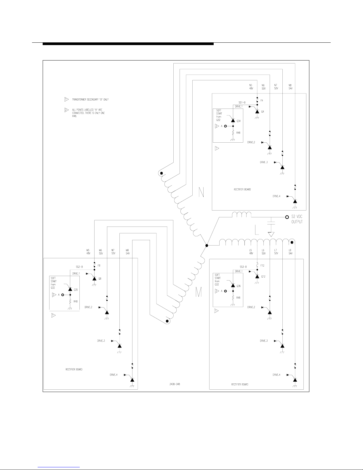
888-2408-002 4-21
WARNING: Discon nect primar y power prior t o servicing .
Overall System Theory
Figure 4-11 3-Phase Power Supply
Simplified Diagram of Transformer and Rectifier Connections
Page 88

4-22 888-2408-002
WARNING: Discon nect primar y power prior to servicing.
Overall System Theory
4.5.1.1 Rectifier Board
The Rectifier Board contains the SCRs which are used for the tap switching as well
as rectification of the 3 phase AC. Each secondary winding has four taps, see Figure
4-11. Each of these taps have one SCR to ground. The Power Supply Controller can
turn on any one of the four SCRs at a given time. If the voltage is not high enough at
the DC output, the PS Controller can change the transformer turns ratio by turning
on a different SCR and therefore utilizing a different secondary tap. The taps closest
to the center will provide the least amount of secondary turns in circuit and will
therefore give the lowest DC output voltage. This means that the taps which are
furthest from the center will give the highest DC output voltage due to more active
turns in the secondary.
There are two rectifier boards mounted on the top of each power transformer. The
two boards were originally made as one board which is broken apart for assembly.
Therefore, there is an “A” side and a “B” side, both of which are shown on the same
schematic. The left side of the schematic is the “B” side and the right side is the “A”
side (except on sheet 3 which is “B” side only). There is also only one part number
for both boards. The “A” Rectifier Board is for the transformer secondary “A” with
the “B” Rectifier Board used with transformer secondary “B”. The Rectifier Boards
are operated in parallel and are tied together by a ribbon cable, J3, which is shown
in the middle of the schematic connecting the “A” and “B” sides.
4.5.1.2 Rectifier Board Circuit Description
Refer to the Rectifier Board schematic and Figure 4-11 for the following. The
Rectifier Boards perform three primary functions:
• Dynamic secondary tap switching using SCRs, to maintain a relatively constant
supply voltage and thus maintain constant transmitter power output despite fluctuations in the 3 phase AC line voltage. It also allows the controller to optimize
transmitter efficiency by selecting the best power supply voltage within its limited range of about 6 volts.
• PA Power Supply Soft-Start.
• PA Power supply Discharge.
Page 89

888-2408-002 4-23
WARNING: Discon nect primar y power prior t o servicing .
Overall System Theory
4.5.1.2.1 Tap Switching Circuit Op eration
The control signals for the SCRs are active high and come directly from the PS
Controller Board. They enter the “B” Rectifier Board at:
• J4-1 - DRIVER 1 (activates SCRs for 48V tap)
• J4-3 - DRIVER 2 (activates SCRs for 50V tap)
• J4-5 - DRIVER 3 (activates SCRs for 52V tap)
• J4-7 - DRIVER 4 (activates SCRs for 54V tap)
NOTE:
The circuit for the 48V tap will be explained here as the other three are identical, but are attached to different transformer taps.
The DRIVE_1 signal is used to activate the 48Vdc tap on T1 and T2 secondaries.
When active (HIGH) it causes the output of U2-17 to go low. This turns on Q28
which applies 10VB-SS, now called DRIVE_1, to R12 on the “B” side of the 48V
section. Interconnect cable J3 then connects the same signal to R25 on the “A” side
Rectifier Board 48V section.
NOTE:
The 10VB-SS (SS = Soft Start) will only be present if the DISCHARGE signal at J4-6 is inactive. See P A Power Supply Dischar ge later in this section for
more information.
The 10VB-SS forward biases diodes CR4, CR8 and CR12 on the “B” side and
CR13, CR17 and CR21 on the “A” side. This turns on the associated SCRs, Q4, Q8
and Q12 for the “B” side and Q13, Q17 and Q21 on the “A” side. Each of the SCR
anodes are tied to ground with the cathode connected through a 30 amp fuse to a tap
on one of the transformer secondaries. The “B” side is connected to L5, M5 and N5
with the “A” side connected to L4, M4 and N4 (see the Overall System Block
Diagram for these connections). Note that both the “A” and “B” side SCRs have
selected the same relative (lowest voltage) taps on each of the two transformer
secondaries.
4.5.1.2.2 PA Power Supply Soft-Start
Soft-Start is used to limit the surge current during transmitter turn on. The Soft Start
and P A Power Supply Discharge circuits are able to use the same resistor, R48 since
only one or the other will be active at any one time. A simplified diagram of the Soft
Start and PA Power Supply Discharge circuits in shown in Figure 4-8. The SoftStart control signal is active high and comes directly from the PS Controller Board,
via J4-8. A high SOFT START signal at J4-8 causes U2-12 to go low . This t urns on
FET switch Q32 which then applies the 10VB-SS through R65 to CR28, CR29 and
CR30. This in turn activates SCRs Q34, Q35 and Q36. The three SCR outputs are
Page 90
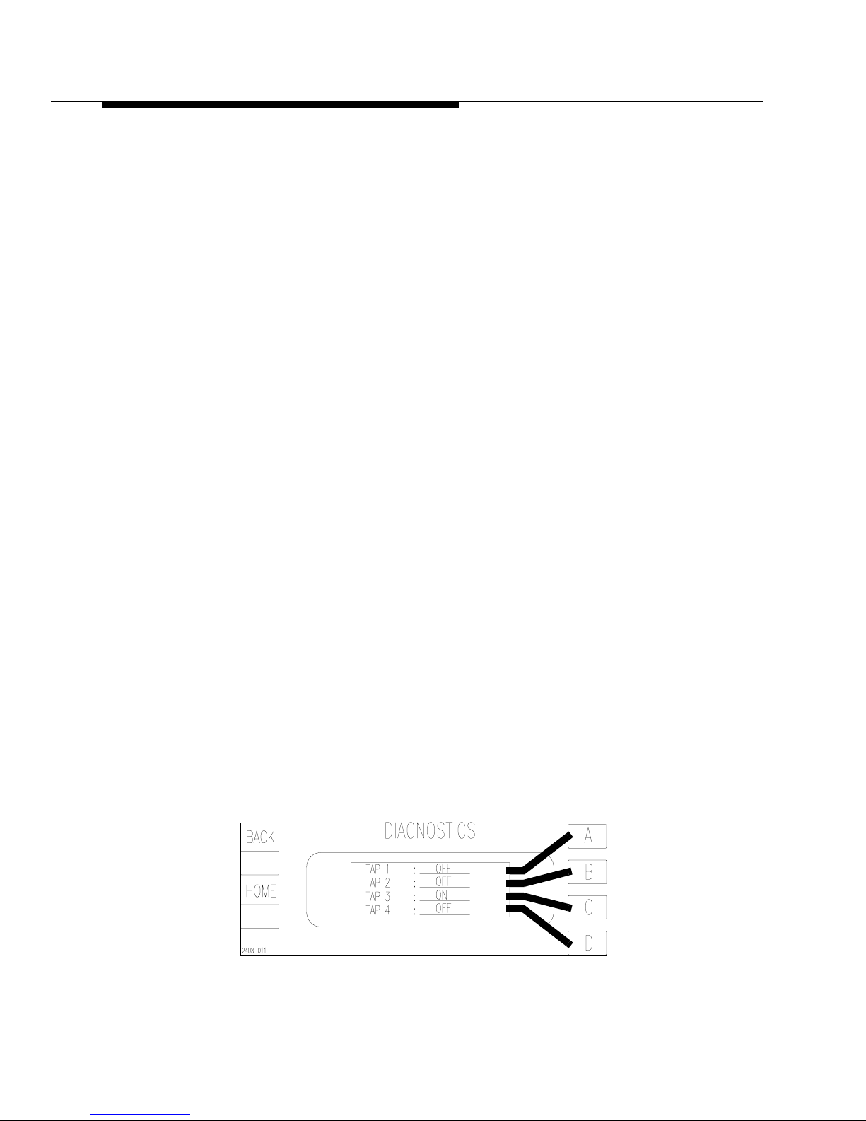
4-24 888-2408-002
WARNING: Discon nect primar y power prior to servicing.
Overall System Theory
labeled SS1-B, SS2-B and SS3-B and are connected to the 48V taps on the
transformer “B” secondaries of T1 and T2. This allows the power supply to start
charging through R48, a 5 ohm 100W current limiting resistor. After about 2
seconds, the DRIVER 1 signal will activate the normal 48V tap SCRs which will tie
the taps directly to ground, bypassing R48.
4.5.1.2.3 PA Power Supply Discharge
The PA Power Supply Discharge circuit uses R48 to bleed down the supply
whenever the transmitter is turned off. The DISCHARGE signal is active low and
comes from the PS Controller Board. When low , it causes the output of U2-14 to go
high. This does two things:
a. First, it reverse biases CR31 which allows the gate of Q33 to pull high
through R54, thus shutting Q33 off. This removes the 10VB-SS used to activate the transformer taps. This prevents the PA Supply (and Soft Start) from
being activated while the DISCHARGE signal is active.
b. Second, it allows the base of Q37 to pull high, shutting it off. R62 will then
pull the gates of Q29 and Q31 low turning them on. Q29 and Q31 are
switches which tie the 52Vdc to R48, and the supply is discharged.
4.5.1.2.4 Voltage Samples
Two AC voltage samples are taken from the 48V taps using 301K ohm resistors.
One from the “A” secondary at J4-14 and one from the “B” secondary at J4-13. The
samples are pulsating DC with a frequency of 360Hz and an amplitude whose
average is equal to the DC power supply output. They are sent to the PS Controller
and used to control the tap switching based on the amplitude of the pulses. The
signals are also bandpass filtered at 60Hz to detect blown SCR fuses and 120Hz to
detect the loss of one AC input phase.
To determine if a tap has failed (blown fuse), refer to the Diagnostics Display. For
Power Supply 1, Press [HOME, STATUS, D,A,A,D] This will show you the screen
in Figure 4-12. Press D again to see the status of Tap 4. For Power Supply 2, Press
[HOME, STATUS, D,C,B,D].
Figure 4-12 Transformer Tap Status
[HOME, STATUS, D,A,A,D]
Page 91

888-2408-002 4-25
WARNING: Discon nect primar y power prior t o servicing .
Overall System Theory
4.5.2 Single Phase PA Power Supply
Refer to the Overall System Block Diagram in the schematic package for the
following discussion. The transmitter single phase AC inputs connect directly to
K1, the AC mains contactor. The transformer side of the contactor is wired in
parallel to power transformers T1 and T2 prima ries in the bot tom of t he t ransmi tte r.
T1 and T2 primaries must be tapped for the proper AC input voltage. The tapping
chart can be found on the Overall System Block Diagram. T1 and T2 can
accommodate input voltages in the range of 198 to 250 Vac.
Each transformer one center tapped secondary with the center connection being the
rectified DC output of 52Vdc. The DC output are filtered by L1, C1, C15 and C16
for T1, and L3, C2, C25 and C26 for T2. Each of the transformer secondary taps is
connected to an SCR which is controlled by ON/OFF signals from the PS Controller
board via the Rectifier Board.
The secondaries of T1 and T2 use the unique tap switching design to give a small
window of coarse regulation (approximately 2Vdc change per tap) to compensate
for AC line variations.
4.5.2.1 Rectifier Board
The SCRs for the single phase are required to carry a much larger amount of current
than the 3-Phase counterparts and are therefore much larger. They are mounted on
large heatsinks on top of the transformers. The SCRs are used for the tap switching
as well as rectification of the AC voltage. Each transformer secondary winding has
8 taps. Each of these taps have one SCR to ground. The secondary is full wave
rectified, which means that one SCR on each side of the center tap is used for each
voltage level. For example CR1 and CR5 on either transformer will be active at the
same time. The other pairs are CR2 and CR6, CR3 and CR7 and C R4 and CR8. The
Power Supply Controller can turn on any pair of the SCRs at a given time. If the
voltage is not high enough at the DC output, the PS Controller can change the
transformer turns ratio by turning on a different SCR pair and therefore utilizing a
different secondary tap. The taps closest to the center will provide the least amount
of secondary turns in circuit and will therefore give the lowest DC output voltage.
This means that the taps which are furthest from the center will give the hi ghest DC
output voltage due to more active turns in the secondary.
Page 92

4-26 888-2408-002
WARNING: Discon nect primar y power prior to servicing.
Overall System Theory
4.5.2.2 Rectifier Board Circuit Description
Refer to the Rectifier Board schematic for the following. The Rectifier Boards
perform three primary functions:
• Dynamic secondary tap switching using SCRs, to maintain a relatively constant
supply voltage and thus maintain constant transmitter power output despite fluctuations in the AC line voltage. It also allows the controller to optimize transmitter efficiency by selecting the best power supply voltage within its limited range
of about 6 volts.
• PA Power Supply Soft-Start.
• PA Power supply Discharge.
4.5.2.2.1 Tap Switching Circuit Op eration
The control signals for the SCRs are active high and come directly from the PS
Controller Board. They enter the Rectifier Board at:
• J4-1 - DRIVER 1 (activates SCRs for 48V tap)
• J4-3 - DRIVER 2 (activates SCRs for 50V tap)
• J4-5 - DRIVER 3 (activates SCRs for 52V tap)
• J4-7 - DRIVER 4 (activates SCRs for 54V tap)
NOTE:
The circuit for the 48V tap will be explained here as the other three are identical, but are attached to different transformer taps.
The DRIVE_1 signal is used to activate the 48Vdc tap on T1 and T2 secondaries.
When active (HIGH) it causes the output of U2-17 to go low. This turns on Q1
which applies 20VB-SS, now called DRIVE_1, to R16.
NOTE:
The 20VB-SS (SS = Soft Start) will only be present if the DISCHARGE signal at J4-6 is inactive. See P A Power Supply Dischar ge later in this section for
more information.
The 20VB-SS forward biases diodes CR3, and CR4. This turns on the associated
SCRs, CR4 and CR8 on each power supply. Each of the SCR anodes are tied to
ground with the cathode connected through a 100 amp fuse to a tap on one of the
transformer secondaries. Note that both power supplies have selected the same
relative (lowest voltage) taps on each of the transformer secondaries.
Page 93

888-2408-002 4-27
WARNING: Discon nect primar y power prior t o servicing .
Overall System Theory
4.5.2.2.2 PA Power Supply Soft-Start
Soft-Start is used to limit the surge current during transmitter turn on. The Soft Start
and P A Power Supply Discharge circuits are able to use the same resistor, R48 since
only one or the other will be active at any one time. A simplified diagram of the Soft
Start and PA Power Supply Discharge circuits in shown in Figure 4-10. The SoftStart control signal is active high and comes directly from the PS Controller Board,
via J4-8. A high SOFT START signal at J4-8 causes U2-12 to go low . This t urns on
FET switch Q5 which then applies the 20VB-SS through R18 to CR28 and CR29.
This in turn activates SCRs Q10 and Q11. The SCR outputs are labeled SS_A and
SS_B, and are connected to the 48V taps, H4 and H8, on the secondary of T1 and
T2. This allows the power supply to start charging through R48, a 5 ohm 100W
current limiting resistor. After about 6 seconds, the DRIVER 1 signal will activate
the normal 48V tap SCRs, CR4 and CR8, which will tie the taps directly to ground,
bypassing R48.
4.5.2.2.3 PA Power Supply Discharge
The PA Power Supply Discharge circuit uses R48 to bleed down the supply
whenever the transmitter is turned off. The DISCHARGE signal is active low and
comes from the PS Controller Board. When low , it causes the output of U2-14 to go
high. This does two things:
a. First, it reverse biases CR31 which allows the gate of Q33 to pull high
through R54, thus shutting Q8 off. This removes the 20VB-SS used to activate the transformer taps. This prevents the PA Supply (and Soft Start) from
being activated while the DISCHARGE signal is active.
b. Second, it allows the base of Q9 to pull high, shutting it off. R62 will then
pull the gates of Q6, Q7, Q12 and Q13 low, turning them on. Q6, Q7, Q12
and Q13 are switches which tie the 52Vdc to R48, and the supply is discharged.
4.5.2.2.4 Voltage Samples
An AC voltage sample is taken from the 48V taps using 200k ohm resistors. One
from SS_A and one from SS_B. The samples are pulsating DC with a frequency of
120Hz and an amplitude whose average is equal to the DC power supply output.
They are sent to the PS Controller and used to control the tap switching based on the
amplitude of the pulses. The signals are also bandpass filtered at 60Hz to detect
blown SCR fuses.
To determine if a tap has failed (blown fuse), refer to the Diagnostics Display.
4.5.2.2.5 Low Voltage Supply Regulators
U1, U3 and U4 regulate the voltages from the Low V ol tage Supply down to 7.1Vdc,
+20Vdc and -20Vdc respectively. These voltages are sent to the controller where
they will be distributed to the individual controller boards. Input voltages to these
regulators will vary depending on the AC mains voltage.
Page 94

4-28 888-2408-002
WARNING: Discon nect primar y power prior to servicing.
Overall System Theory
4.5.2.2.6 16VCT, V+SCR Supply
The 16VCT secondary winding is fused by F3 and F4 on the Rectifier Board. These
are self-resetting fuses which physically look like disc capacitors. The AC is
rectified by CR10 and CR11 and becomes V+SCR which i s the gate drive signal for
the tap and soft start SCRs.
4.5.2.2.7 Heat Sink Temperature
The temperature of the rectifier heatsink is monitored by Thermistor , R T1. A fault is
triggered if the temperature of the rectifier heatsink exceeds 100°C and the power
supply will be shut off. This t emperature can be monitored in the S tatus Menu of the
Diagnostics Display. If the thermistor is shorted, the temperature reading will be
about 155°C and the supply shut off. If it is open it will cause a Thermistor Fault to
show up in the fault log.
4.5.3 Power Supply ID Jumpers
The 3 Phase and Single Phase supplies both have ID jumpers which are set to
designate the power supply as PS1 or PS2. This lets the PS Controller know which
power supply it is connected to, for proper reporting to the Master Controller. The
PS Controller will not allow 2 IDs to be the same. The jumper configurations are
given below: These jumpers are located on the Rectifier Boards on both the 3 Phase
and Single Phase supplies.
4.5.4 Low Voltage Power Supply Board
The AC input for this board is dependent on the AC voltage and configuration for
the transmitter, 3-phase Delta (3 wire), 3-phase WYE (4 wire) or single phase. The
same board is used in all three cases. The AC inputs to the board come from circuit
breaker, CB1, and enter the board at J1-1 and J1-4. For the 3-phase Delta and Single
Phase J1-1 is Phase A and J1-4 is Phase B (Phase C for the 3-Phase does not
connect to this board). For the 3-phase 4 wire WYE J1-4 is Phase B and J1-1 is the
Neutral.
Transformer T1 has dual full wave rectifiers. The T1 secondary outputs are fused by
F3, F4, F5 and F6, and are then full wave rectified for two DC outputs of +10Vdc.
The +10Vdc is filtered by C1-C6 and connected to t he rectifier boards, on top of the
PA power supply transformers, in the bottom of the transmitter. Transformer T2
secondaries are fused by F7, F8, F9 and F10 before going to dual bridge rectifiers.
The rectifier outputs are filtered by C7-C10 and supply +20Vdc and -20Vdc to the
PS #1 PS #2
JP1 IN OUT
JP2 OUT IN
JP3 OUT OUT
Page 95

888-2408-002 4-29
WARNING: Discon nect primar y power prior t o servicing .
Overall System Theory
Rectifier Boards on the PA power supply transformers. All three voltages pass
through the rectifier boards and are sent to the Backplane Board to power all of the
controller PC boards.
4.5.4.1 Relays
There are three mechanical relays on the Low Voltage Power Supply Board
assembly A19. They are A19K1, A19K2 and A19K3. The relays are powered by
+12Vdc from the Life Support Board in the controller.
• A19K1 is activated when the transmitter is turned on and the
“CONTACTOR_ON” signal from the Life Support Board goes low. When acti-
vated, A19K1 supplies Phase A (or Neutral) to the coil of the AC mains contactor
K1 (and K3 in the Auxiliary cabinet for the single phase), which then supplies
AC to the PA power supply transformers.
• A19K2 is activated by the same “CONTACTOR_ON” signal and supplies Phase
B to the exciter(s). Note that this means the exciter(s) will not have power until
the transmitter is turned on.
• A19K3 is activated by the active low “FAN_SPEED_SELECT” signal from the
Life Support Board. A19K3 activates the fan speed select relay K2 mounted next
to the AC mains contactor on the cabinet wall. K2 is shown on the Overall System Block Diagram in the HIGH fan speed position. When A19K3 pulls in so
does K2 (not A19K2).
4.6 Cooling System Description
The transmitter is cooled by the single, two speed fan in the lower rear of the
transmitter. It uses a high volume, low velocity, air system. Air ducting for inlet air
should be well filtered and, if possible, at a slightly positive pressure. The exhaust
air ducting should cause very little or no back pressure due to the low velocity air
system. Air handling recomme ndations are shown on th e Cabinet Outline Drawings
in the schematic package.
Upon transmitter turn on, the fan will run at high speed for one minute, then will
normally run at the low speed until a fault occurs or there is a significant increase in
temperature detected by the controller. The blower motor is a 2 speed, single phase
motor. Contactor K2 selects the fan speed and is controlled by the Master
Controller. The fan speed can also be manually set to HIGH speed or AUTO in the
Configuration Menus of the Diagnostics Display.
Page 96

4-30 888-2408-002
WARNING: Discon nect primar y power prior to servicing.
Overall System Theory
4.7 Control System Description
The control system is a micro-controller based master/slave system. It monitors
over 100 operating functions in the transmitter and can make intelligent operating
decisions based on operating conditions. It has the standard parallel remote
connections. The microprocessor control system allows fast and efficient
monitoring of the entire transmitter offering a level of protection and diagnosti cs not
available with a simple logic controller. It also makes changes and upgrades a
simple matter of changing the firmware.
The Controller consists of the following boards:
• Master Controller Board
• PA Controller #1
• PA Controller #2
• Power Supply Controller #1
• Power Supply Controller #2 (Optional)
• Life Support Board
• Display/Backplane Board (motherboard)
All of these boards are locate d directly behind the transmitter c ontrol panel and plug
into the Display/Backplane Board. The entire assembly is considered the “System
Controller”.
The Controller functions include:
• Transmitter Control Functions
• Automatic Power Control, or APC
• VSWR Monitoring and Overload Protection
• Power Supply Monitoring and Protection
• Power Amplifier Monitoring and Protection
• Automatic power foldback for VSWR, Over-temperature and Over-current con-
ditions.
• AC Restart
• System Calibration and Configuration
• Detailed Status, Metering, Configuration and Fault Diagnostics display screens.
Page 97

888-2408-002 4-31
WARNING: Discon nect primar y power prior t o servicing .
Overall System Theory
4.7.1 Master Controller
The Master Controller is responsible for primary transmitter control and is the
summary point for all of the information gathering. It controls and/or receives
information from the PA Controllers, Power Supply Controllers and Life Support
Board and takes action appropriate to the operating conditions of the transmitter. It
is also responsible for the transmitter power control, system configuration,
calibration, VSWR protection and the Transmitter and Diagnostics displays on the
front panel.
However, the rest of the control system is designed to operate with the Master
Controller removed from the system in what is called Life Support Mode. The PA
and PS Controllers report to the Master Controller but operate independently to
allow them to continue operating even if the Master is removed. In the event of a
Master Controller failure the Life Support Board disconnects all Master Controller
control functions from the transmitter and initiates minimal protection and control
to keep the transmitter on the air. For more information on Life Support Mode, refer
to the Life Support Board description later in this section.
4.7.1.1 EEPROM U39
The Master Controller has 3 memories, ROM (firmware), RAM (volatile) and an
EEPROM (non-volatile) U39. When the low voltage is applied to the controller it
loads up the program from ROM to RAM and then goes to the EEPROM for all of
the transmitter configuration, calibration settings, power levels, fault limits etc..
Basically EEPROM U39 stores any settings that can be changed in the Diagnostics
Display. Any changes made in the Diagnostics Display will be either automatically
saved in the EEPROM or is saved when the [BACK] button is pressed (ie. Back to
Update).
All the individual bits or bytes of information stored here have a default setting
which is stored in the firmware ROM. When the information in U39 is uploaded to
RAM it is checked against the default values. If it is considered to be out of
tolerance (or invalid data) it will automatically be replaced with the default value
from the ROM. When this happens the fault “EEPROM_DEF” (Default) will be
placed in the fault log. The only time this should happen is when a new EEPROM,
U39 is installed in the Master Controller. Since it is basically blank, all of the
default settings from the ROM will be written to U39 one at a time as it finds they
are out of tolerance. After this has happened, the EEPROM_DEF fault should never
happen again. If it does, U39 should be replaced since a memory location is
probably bad. For information on replacing EEPROM U39 see Section V,
Maintenance and Alignments
Page 98

4-32 888-2408-002
WARNING: Discon nect primar y power prior to servicing.
Overall System Theory
The following is a listing of all of the Default Values which are stored in the
Firmware:
• Forward Factor - 0.007697
• Reflect Factor - 0.000306
• Cal APC Factor - 7.58
• Cal Frequency - 98MHz
• Operating Frequency - 98MHz
• IPA Factor - 200
• Exciter Factor - 200
• TPO 100% - 05.00kW
• Max High - 06.00kW
• Max Low - 2.50kW
• UPS Setting - 2.50kW
• Low Power Alarm - 4.50kW
• VSWR Foldback - 1.35
• VSWR Fault - 1.5
4.7.1.2 APC, Automatic Power Control
One important function of the Master Controller is tran smitter power control, which
is accomplished via the APC Loop. The APC Loop controls the transmitter power
and keeps it constant by varying the IP A RF output indirectly proportionate with the
forward power. In other words, if the forward power output goes up, the IPA output
will be reduced, which will in turn reduce the PA RF output. If the forward power
output goes down, the IPA RF output will be increased, which will increase the PA
RF output to compensate.
The APC loop starts at the forward power directional coupler. The forward sample
is connected to the Life Support Board where it is calibrated with R127 for 8.9V@
100% TPO at TP9. This voltage sample is then sent to the Master Controller
(schematic sheet 7) where it is squared by multiplier chip U1 (to make the voltage
from the coupler proportional to power) and divided by 10. This is then sent to U56 where it is compared to APC_REF voltage (APC Reference).
APC_REF is the DC output of a D/A Converter or DAC whose input is called
DAC_APC_REF and is controlled by the RAISE and LOWER buttons on the front
of the controller (or by the remote control inputs) or can be varied automatically by
the Master Controller’s foldback routines. Pressing RAISE increases the APC_REF
voltage and pressing LOWER decreases it. The DAC_APC_REF is responsible for
Page 99

888-2408-002 4-33
WARNING: Discon nect primar y power prior t o servicing .
Overall System Theory
all transmitter power control functions including power level, foldbacks and mute.
This makes it a very important number to know and understand for troubleshooting.
NOTE:
As calibrated from the factory, the digital DAC_AP C_REF number should be
approximately 660 (this number should be on the factory test data sheet). This
number can be checked by pressing [HOME, MORE, CONFIGURATION
C,B]. The DAC_APC_REF output voltage APC_REF can be metered at TP8
or in the Diagnostics Display, press [METERING, B,B].
The output at U5-7 is the difference between the forward power sample and the
APC_REF voltage. This difference can be measured at TP3 on the Master
Controller and is called the APC voltage. R13 and R102 divide this voltage down
for display on the Transmitter LCD Display on the right side of the controller. The
APC voltage is not the same as the APC_REF voltage. The dipswitch, S1-10, is
present to allow the APC loop to be opened for troubleshooting. This APC voltage
is now sent back to the Life Support Board (Schematic, sheet [3,B8]) and is called
MSTR_IPA_CTL (Master IPA Control).
If the Master Controller is operational, then the MSTR_IPA_CTL signal will pass
through to U5-4 which will in turn pass the signal if there are no System Mutes
present. Due to the low impedance of the circuit, the Manual PWR REF pot R25 has
little or no effect on the circuit. CR4 and R30 shift the positive APC voltage to a
proportional negative voltage which is passed on to IP A_AB1 or AB2 depending on
the position of K2. Remember that the gate bias on the RF amplifiers is -18V for
OFF and -0.6V for fully ON.
Since the exciter power is fixed, cha nging the IPA bias will increase or decrease the
IPA output which will then proportionately increase or decrease the output of the PAs.
EXAMPLE:
The following is an example of how the entire loop would work. For our example
the power output of the transmitter goes down due to a failed PA. This would
decrease the output of the forward power directional coupler and the voltage at the
input to the difference amp at U5-6 on the Master Controller Board. Since U5 has
almost infinite gain, the loop will try to force the forward power sample input to U5
to be the same as the APC_REF input. This will increase the APC voltage at TP3
and on the front panel APC reading. The increased APC voltage will pass through
the U5 analog switches (on the Life Support Board) bringing the input to U15-3 less
negative. This less negative voltage is sent to the IPA, increasing its output. More
drive to the PA will increase the transmitter RF output to compensate for the failed
PA. If the RF power output were to increase, the APC loop voltage would be
reduced, lowering the IPA and PA output.
Page 100

4-34 888-2408-002
WARNING: Discon nect primar y power prior to servicing.
Overall System Theory
4.7.1.2.1 Manual Power Control
It is possible to shut off the APC by opening dip-switch S1-10 (Open = OFF) on the
Master Controller Board. This switch opens the APC Loop, disconnecting the APC
voltage from the IPAs. When S1-10 is opened, MANUAL PWR REF R25 on the
Life Support board controls the transmitter power output. R25 also serves as the
power control for Life Support Mode which means the Master Controller Board has
failed. If the Master Controller fails, U5 pins 1-2 are opened, removing the APC
voltage from the IPAs, breaking the APC loop. In Life Support Mode, R25 is set to
operate the transmitter at 25% of rated power. Proper setting of R25 requires an
external wattmeter and is covered in Section V, Maintenance under “Setting Life
Support Power Level.”
!
CAUTION:
IN LIFE SUPPORT MODE THERE IS LIMITED OVERLOAD PROTECTION
AND NO FOLDBACK FUNCTIONS. ADJUSTING R25 TO MORE THAN 25%
RATED POWER WILL CAUSE THE TRANSMITTER TO SHUT OFF AND
COULD DAMAGE THE TRANSMITTER. REFER TO SETTING LIFE
SUPPORT POWER LEVEL IN SECTION V, MAINTENANCE.
4.7.2 Calibration Factors and A/D Values
The configuration menus in the Diagnostics Display contain the calibration factors
and A/D values used by the transmitter for calibration, operation and protection.
The cal factors are calculated by the micro when the transmitter is calibrated. The
A/D readings are the decimal equivalents of the forward and reflected power sample
voltages. The following is a listing of their nominal values:
Calibration Factors:
• Forward Factor - 0.007697
• Reflect Factor - 0.000306
• APC_Factor - 7.58
• EXC_Factor - See Factory Test Data (Frequency dependent)
• IPA_Factor - See Factory Test Data (Frequency dependent)
A/D Readings
• DAC_APC_REF - 660 (nominal)
• A/D_FWD_PWR - 806 (nominal @ 5kW)
• A/D_RFL_PWR - 700 (nominal @ 150W reflected)
 Loading...