

Page 1

Installation and user guide
Inverter
3800 TL, 3801 TL, 4300 TL, 4800 TL, 5300 TL, 6300 TL, 7200 TL
As at 10/2013, Material no. 747 405-AD
EN
Page 2

2
Installation and user guide for PLATINUM® inverters 3800 TL, 3801 TL, 4300 TL, 4800 TL, 5300 TL, 6300 TL, 7200 TL
Page 3

3
Installation and user guide for PLATINUM® inverters 3800 TL, 3801 TL, 4300 TL, 4800 TL, 5300 TL, 6300 TL, 7200 TL
Contents
1 Introduction 5
1.1 PLATINUM® TL 5
1.2 About this manual 5
1.3 Symbols used 5
1.4 Symbols on product and packaging 6
2 Safety 7
2.1 Intended usage 7
2.2 Improper usage 7
2.3 Personnel requirements 7
2.4 General safety instructions 7
3 Installation 8
3.1 Scope of delivery 8
3.2 Unpacking 8
3.3 Assembly 9
3.4 Connection 13
4 Placing into operation 22
4.1 Switch on 22
4.2 Initial operation 22
4.3 Initial operation menu 23
5 Operation 27
5.1 Display 27
5.2 Operation display 28
5.3 Isolation from the generator field 30
6 Menu 31
6.1 Operate and navigate in the menu 31
6.2 Menu tree 32
6.3 SETTINGS menu 33
6.4 INFORMATION menu 35
6.5 Service menu 36
Contents
Page 4

4
Installation and user guide for PLATINUM® inverters 3800 TL, 3801 TL, 4300 TL, 4800 TL, 5300 TL, 6300 TL, 7200 TL
7 Maintenance and cleaning 41
7.1 Maintenance 41
7.2 Cleaning 41
8 Errors and troubleshooting 42
8.1 Error display 42
8.2 Event list 44
9 Technical data 48
10 Taking out of operation 52
11 Disposal 53
Contents
Page 5

5
Installation and user guide for PLATINUM® inverters 3800 TL, 3801 TL, 4300 TL, 4800 TL, 5300 TL, 6300 TL, 7200 TL
Introduction
1 Introduction
1.1 PLATINUM® TL
The inverters in the PLATINUM® TL series are single-phase feed-in inverters for different power ranges, see “Technical data” on page 48.
With the aid of the PLATINUM® network (EIA485), up to 50 PLATINUM® inverters can
be connected to form a system.
Options
The following options are available to enhance an inverter or inverter system:
▪ Remote monitoring or remote readouts with the PLATINUM® WebMaster
▪ Evaluation of plant data with the PLATINUM® PV monitor
▪ Remote-controlled AC power reduction via an external monitoring device
1.2 About this manual
This installation and operating manual describes the installation
and operation of the PLATINUM® inverters of the types
3800 TLD, 3801 TLD, 4300 TLD, 4800 TLD, 5300 TLD, 6300 TLD, 7200 TLD.
Additional documents
The following additional documents are available in the download area of our website
www.platinum-nes.com:
▪ Detailed installation and user guide
▪ Information on fault current protection devices
▪ Detailed event list for detecting/eliminating errors
▪ Overview of country and grid codes
▪ Declaration of conformity and certificates
▪ Manufacturer’s warranty
1.3 Symbols used
1.3.1 Structure of warnings
WARNING WORD
Type, source and consequence of the hazard!
f Measures to avoid the hazard.
Page 6

6
Installation and user guide for PLATINUM® inverters 3800 TL, 3801 TL, 4300 TL, 4800 TL, 5300 TL, 6300 TL, 7200 TL
Introduction
1.3.2 Hazard levels in warnings
Symbol Warning
word
Probability of occurrence Consequences of non-obser-
vance
DANGER Imminent danger Death, serious injury
WARNING Potential danger Death, serious injury
CAUTION Potential danger Minor injury
– CAUTION Potential danger Damage to property
1.3.3 Notes
Notes give tips on how to work easily and safely or contain further information.
1.4 Symbols on product and packaging
The following sticker is attached to the inverter:
Page 7

7
Installation and user guide for PLATINUM® inverters 3800 TL, 3801 TL, 4300 TL, 4800 TL, 5300 TL, 6300 TL, 7200 TL
Safety
2 Safety
2.1 Intended usage
▪ Inverters are to be used solely for the purpose of feeding photovoltaically generated
solar energy into the public grid.
▪ All other usage does not comply with the regulations.
2.2 Improper usage
▪ The inverters are not to be used in off grid PV plants.
▪ The inverters are not to be used in vehicles.
▪ The inverters are not to be used in areas at risk of explosion (flour dust, sawdust, etc.).
▪ The inverters are not to be exposed to direct sunlight.
▪ The inverters are not to be used in areas in which the ammonia content of the air
exceeds 20 ppm.
▪ All warranty claims will be rendered null and void in the event of failure to comply
with the warranty terms or the information provided in this operating and installation
manual.
2.3 Personnel requirements
The inverter may only be installed and put into operation in accordance with this
installation and user guide by trained specialist personnel, for example:
▪ Service partners authorised by PLATINUM GmbH
▪ Authorised specialist personnel with knowledge of the applicable guidelines and
standards
2.4 General safety instructions
▪ The inverters are to be used in their original state without independent modifications
and in a technically perfect condition.
▪ Steps must be taken to ensure that the following are adhered to when assembling
and connecting the inverter and the PV system:
– Guidelines and regulations valid in the respective country
– Provisions of the trade associations, TÜV, VDE (Association for Electrical, Electronic
& Information Technologies)
– Technical connection conditions of the energy supplier responsible
– National and international regulations and provisions
▪ Ensure that all protection devices are working correctly.
▪ Observe the operating conditions; see “Technical data” on page 48.
Page 8
8
Installation and user guide for PLATINUM® inverters 3800 TL, 3801 TL, 4300 TL, 4800 TL, 5300 TL, 6300 TL, 7200 TL
Installation
3 Installation
3.1 Scope of delivery
▪ Inverter
▪ Wall bracket
▪ Brief guide
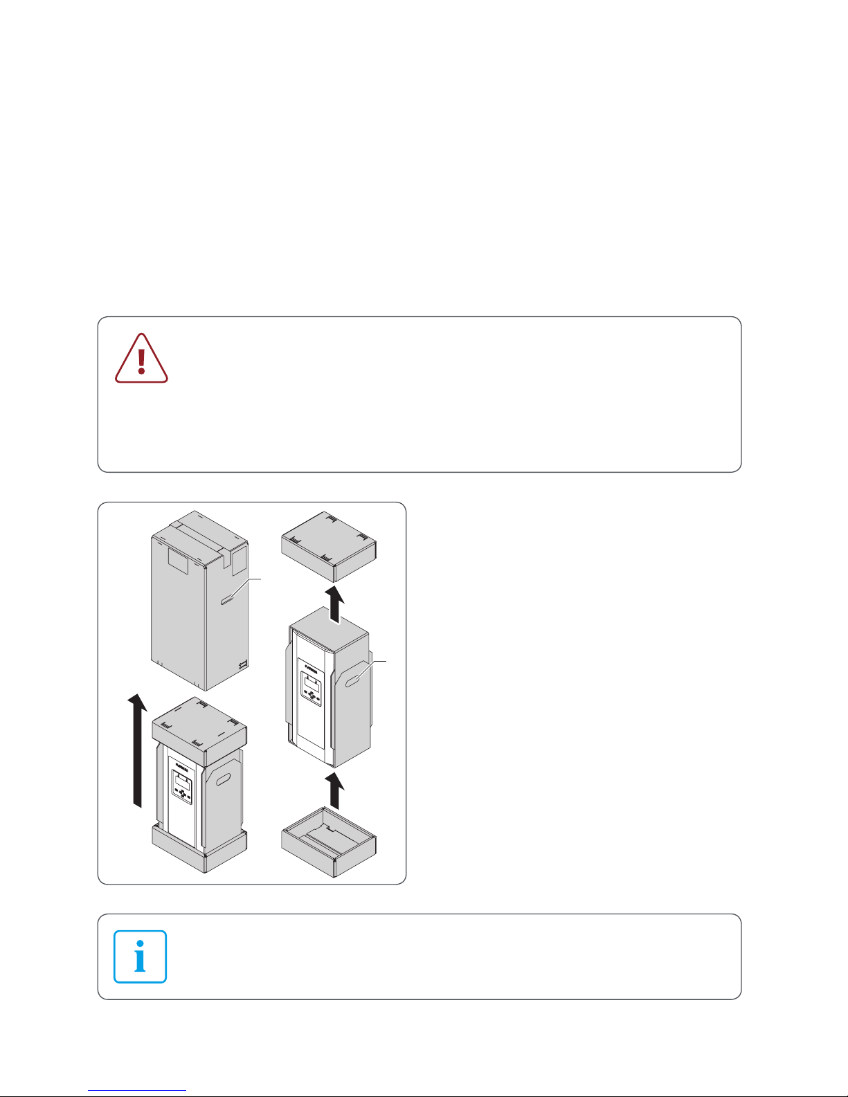
3.2 Unpacking
CAUTION
The inverter is heavy!
f Ask another person to help you unpack and lift it.
f Wear safety shoes when unpacking the inverter and during
installation.
f Ensure that the inverter is positioned securely.
3.
4.
5.
2
1
1. Place the box upright (note the
lettering on the box).
2. Cut the retaining straps without
damaging the box.
3. Grab the handle openings (1) on the
outer jacket of the box and lift it up
and off.
4. Take off the cover from the box.
5. Lift the inverter by the handle
openings (2) out from the bottom of
the box.
6. Set down the inverter.
The supplied brief guide is located underneath the protector; see 13.
Page 9

9
Installation and user guide for PLATINUM® inverters 3800 TL, 3801 TL, 4300 TL, 4800 TL, 5300 TL, 6300 TL, 7200 TL
Installation
3.3 Assembly
3.3.1 Safety instructions
WARNING
Injury may result if the inverter falls!
f Use fixing materials suited to the assembly wall and the weight of the
inverter.
f Get a second person to help with assembly and disassembly.
f Wear safety shoes during assembly and disassembly.
f Ensure that the inverter is positioned securely.
CAUTION
Material damage due to excessive build-up of dust!
The protection class IP66 does not apply to the communication interface.
f Avoid excessive build-up of dust.
f Avoid build-up of dust with electrically conductive dust particles.
In order to comply with the requirements of standard IEC-62109, a
possibility must be provided for tool-free isolation of the solar generator.
If the design does not feature an integrated DC isolator then an external
isolation device is mandatory; this must be easily accessible.
PLATINUM GmbH recommends that the inverter should not be installed
in living quarters.
Page 10

10
Installation and user guide for PLATINUM® inverters 3800 TL, 3801 TL, 4300 TL, 4800 TL, 5300 TL, 6300 TL, 7200 TL
Installation
3.3.2 Disassemble the wall bracket from the inverter.
4
3
1. Loosen but do not remove the safety
screws on the sides (3).
2. Grab the wall bracket (4) at the bottom
and lift it up off the inverter.
Page 11

11
Installation and user guide for PLATINUM® inverters 3800 TL, 3801 TL, 4300 TL, 4800 TL, 5300 TL, 6300 TL, 7200 TL
Installation
3.3.3 Mounting the inverter
The upper cutout in the wall bracket corresponds to the position of the
display and buttons on the mounted inverter.
≥191
≥177
Ø9
≥500
344
125125
≥232
115
≥494
≥920
285
Dimensions in mm
1. Choose a suitable location for assembly. Take into account dimensions and
distances.
2. Fix the wall bracket to the assembly wall with suitable fixing materials.
Page 12

12
Installation and user guide for PLATINUM® inverters 3800 TL, 3801 TL, 4300 TL, 4800 TL, 5300 TL, 6300 TL, 7200 TL
Installation
3
5
5
3
3
4
5
1. Working from underneath, hook the
hanger of the inverter (5) at the top in
the slotted piece of the wall bracket
(4).
2. Ensure that the inverter is fitted
correctly on the wall bracket.
3. Secure the inverter by tightening the
safety screws (3) on the sides.
Page 13

13
Installation and user guide for PLATINUM® inverters 3800 TL, 3801 TL, 4300 TL, 4800 TL, 5300 TL, 6300 TL, 7200 TL
Installation
3.4 Connection
3.4.1 Preparatory work
On devices with a DC disconnect
t Move the switch knob of the DC
disconnect on the underside of the
device to the “0” position.
On devices without a DC disconnect
t Disconnect the DC voltage side with
the external isolation device from the
solar generator.
6
7
1. Grab the protector (6) by its underside
and pull it off the inverter.
2. Take out the brief guide (7).
3. Hang the protector in one of the
holders on the sides of the inverter.
Page 14

14
Installation and user guide for PLATINUM® inverters 3800 TL, 3801 TL, 4300 TL, 4800 TL, 5300 TL, 6300 TL, 7200 TL
Installation
3.4.2 Connect the AC voltage
DANGER
Risk of death due to high AC voltage!
f Switch off the mains voltage supply (AC side) before connecting the
inverter (safety device).
f Make sure that the central isolation device can be accessed freely.
f Only connect the inverter to TN or TT networks (see IEC 60364-1) with
230 V.
f Observe max. fuse protection permitted on the AC voltage side, see
“Technical data” on page 48.
f Make the AC voltage connection with a cable isolator switch.
PLATINUM GmbH recommends a type C cable isolator switch.
f If an external residual current protective device is required, PLATINUM
GmbH recommends using a residual current protective device (RCD)
of type A.
CAUTION
Destruction of the inverter!
f Never connect inverters between two phases.
f Never mix up the phases with PE or N.
f Distribute the inverters across the three phases in such a way that the
differences between the AC power levels on the different phases do
not exceed the maximum permitted unbalanced load of the network
operator.
Prepare the connection cable for the AC voltage
Dimensioning the wire cross section is the responsibility of the
electrician and depends on the cable length and installation situation.
▪ Min. cross section 4 mm
2
▪ Max. cross section 16 mm
2
1. Protect the AC voltage connection lines with appropriate fuses, see “Technical data”
on page 48.
2. Strip 18 mm of insulation from the AC voltage connection lines and add wire-end
sleeves.
Page 15

15
Installation and user guide for PLATINUM® inverters 3800 TL, 3801 TL, 4300 TL, 4800 TL, 5300 TL, 6300 TL, 7200 TL
Installation
Connect
8
1. Take off the cover (8) from the AC
voltage connection by removing
4 screws.
2. Put the screws in the row of holes.
3. Unfasten the AC screw connection (9)
with seal from the underside of the
inverter.
The cable entry is sealed with a thin
protective layer (10) against external
influences. This protective layer needs to
be removed.
4. Direct the prepared AC voltage
connection line through the AC screw
connection and seal.
5. Feed the AC voltage connection line
into the housing from below.
6. Tighten the AC screw connection.
Page 16

16
Installation and user guide for PLATINUM® inverters 3800 TL, 3801 TL, 4300 TL, 4800 TL, 5300 TL, 6300 TL, 7200 TL
Installation
L N PE 1 2
LNPE 12
7. Connect the AC voltage connection
cable to the inverter:
– Open the terminal with a
screwdriver.
– Insert the conductor.
– Remove the screwdriver.
Terminal Assignment
L Feed phase L1
N Neutral
PE Potential equalisation
1 Monitoring phase L2,
for 3-phase ENS only
2 Monitoring phase L3,
for 3-phase ENS only
8. Refit the cover of the AC voltage
connection using the 4 screws
3.4.3 Connect DC voltage
DANGER
Risk of death due to high DC voltage! A voltage is present at the
PV modules when it is bright.
f Before connecting the inverter, check whether voltage is applied to
the generator’s DC voltage connection.
f Before connecting the inverter, check whether the polarity of the
DC voltage is correct.
f If voltage is applied, wear insulating protective clothing and face
protection.
f Ensure that the cable plug has engaged completely with the socket.
f Detach the DC voltage cable only if the inverter is not in operation.
f Make sure that the DC isolator or a central isolation device can be
accessed freely.
f Do not ground the poles of the PV modules. The inverter does not
have a transformer.
Page 17

17
Installation and user guide for PLATINUM® inverters 3800 TL, 3801 TL, 4300 TL, 4800 TL, 5300 TL, 6300 TL, 7200 TL
Installation
WARNING
Risk of electric shock and material damage!
f Use only the original DC voltage Multi-Contact MC4 cable plug.
f Only connect PV modules that meet the requirements of
IEC 61730 class A.
f Ensure that the max. DC voltage permitted is not exceeded.
f Ensure that the max. direct current permitted per string is not
exceeded.
If more than one string is connected, make sure that the quantity and
type of solar modules and the voltage of strings to be connected in
parallel are the same.
–
+
–
+
1. Fit original Multi-Contact MC4 connectors to each string of the DC voltage
cable. Make sure that the polarity is
correct here.
2. Take off the protective caps from the
required DC voltage connections.
3. Insert the prepared DC voltage
connectors into the DC voltage
connections. In the process, make
sure that the connectors lock in place
correctly.
Fit protective caps to plug connectors that are not used on the inverter.
Page 18

18
Installation and user guide for PLATINUM® inverters 3800 TL, 3801 TL, 4300 TL, 4800 TL, 5300 TL, 6300 TL, 7200 TL
Installation
3.4.4 Connection to the PLATINUM® network (EIA 485)
Up to 50 PLATINUM® inverters can be connected with monitoring
devices into a network with an overall length of up to 1000 m.
Network cable
▪ CAT 5 shielded twisted pair cable with pre-assembled RJ45 plugs (pin 3 = B and
pin 6 = A)
– or –
▪ Twisted pair of wires of a CAT 5 cable
Connect
11
1. Take off the cover (11) from the terminal strip.
Page 19

19
Installation and user guide for PLATINUM® inverters 3800 TL, 3801 TL, 4300 TL, 4800 TL, 5300 TL, 6300 TL, 7200 TL
Installation
shield
EIA 485
12
EIA 485
ABA
B
0 V
+ 12 V / max. 30
N.C.
optional Input (m
24V
2. Connect the network cables in the
inverter.
CAT 5 cable with RJ45 plug
▪ Incoming cable: Socket 1
▪ Outgoing cable: Socket 2
CAT 5 cable with 2 twisted wires
▪ Incoming cables:
Left-hand terminals A, B
▪ Outgoing cables:
Right-hand terminals A, B
▪ Shielding: Shield
t Ensure that signal lines A and B are
not connected incorrectly.
Termination
An integrated terminating resistor can be activated at both open ends of the network (at
the first and last inverters).
Terminating ensures that the network functions correctly.
12
1. Remove the terminating plug (12)
from the protector.
2. Connect the terminating plug to
socket 1 of the first and last inverter.
Page 20

20
Installation and user guide for PLATINUM® inverters 3800 TL, 3801 TL, 4300 TL, 4800 TL, 5300 TL, 6300 TL, 7200 TL
Installation
3.4.5 Further connections on the terminal strip
On the terminal strip, there are further terminals for the connection of a potential-free
alarm contact, an external consumer and an input.
shieldABAB
0 V
+ 12 V /
N.C.
optional
1234567
(1) Alarm contact (NC contact)
(2) Alarm contact (centre contact)
(3) Alarm contact (NO contact)
(4) Not used
(5) Input, 12 V max. (optional)
(6) Supply voltage for external
consumer, 12 V, 300 mW max.
(7) Supply voltage for external
consumer, 0 V
Alarm contact
In the event of a fault, the contact closes and activates the alarm system (visual or
acoustic) if required.
t For the supply voltage, only use a safety extra-low voltage (SELV) with a maximum
voltage of 24 V.
The alarm contact can be configured in the menu
SETTINGS –> ALARM FUNCTION; see 34.
Page 21

21
Installation and user guide for PLATINUM® inverters 3800 TL, 3801 TL, 4300 TL, 4800 TL, 5300 TL, 6300 TL, 7200 TL
Installation
3.4.6 Final tasks
6
1. Refit the cover on the terminal strip.
2. Take off the protector (6) from the side
position.
3. Place the upper part of the protector
on the upper holder and gently press
it onto the housing.
4. Slide the lower part of the protector
into the lower holder.
Page 22

22
Installation and user guide for PLATINUM® inverters 3800 TL, 3801 TL, 4300 TL, 4800 TL, 5300 TL, 6300 TL, 7200 TL
Placing into operation
4 Placing into operation
4.1 Switch on
1. Switch on mains voltage supply (safety device).
2. Switch on the DC voltage via the DC disconnect
on the underside of the device or via the external
isolation device.
The inverter type appears on the display along
with the prompt “START?”.
4.2 Initial operation
▪ To transfer all settings correctly, initial operation must be conducted in
full once.
▪ When installing several inverters that are linked with each other via the
PLATINUM® network (EIA485), initial operation can be performed on
any inverter (master programming). For this to be possible, all inverters
in the network must be switched on.
▪ The inverter automatically transfers the setting values to the other
inverters via the PLATINUM® network (EIA485).
▪ Every inverter is allocated a number automatically during initial
operation. This number can be changed and freely assigned in a further
step.
▪ The inverters on which no data is entered display different screen
content depending on the menu. If data cannot be entered, the
inverter displays the start screen.
▪ During initial operation, all inverters connected to the PLATINUM®
network are blocked.
Page 23

23
Installation and user guide for PLATINUM® inverters 3800 TL, 3801 TL, 4300 TL, 4800 TL, 5300 TL, 6300 TL, 7200 TL
Placing into operation
4.3 Initial operation menu
4.3.1 Overview
The initial operation menu distinguishes between the initial operation of a device
in a new PLATINUM® network to be configured and modifications to an existing
PLATINUM® network (exchange inverter, reconfiguration).
Initial operation Exchange inverter/reconfiguration
Start Start
Language Language
Network scan Network scan
Change device number Exchange inverter
Reassign numbers
Country code * Country code *
Date Date
Time Time
* The country code can only be changed for a period of four hours after
initial operation and feed-in starts. This menu will not be displayed later.
Page 24

24
Installation and user guide for PLATINUM® inverters 3800 TL, 3801 TL, 4300 TL, 4800 TL, 5300 TL, 6300 TL, 7200 TL
Placing into operation
4.3.2 Description of the initial operation menu
Changing the date and time can cause saved data to be overwritten or
lead to gaps in data logging.
During initial operation, the date and time must be entered completely
once.
Initial operation menu
Start
Confirm prompt with OK.
Language
Select the language required using the / buttons and confirm
with OK.
Network scan
The inverter scans the PLATINUM® network connected and then
displays the number of participants and inverters in the network.
▪ If the number of participants and inverters is correct, confirm with
OK.
▪ If the number of participants and inverters displayed is not
correct:
– Check the wiring.
– Select REPEAT using the / buttons and confirm with OK.
The inverter recognises only those network participants that are
correctly connected via the PLATINUM® network.
Change
device
number/
reassign
numbers
During initial operation, the inverter numbers are assigned
automatically in the network.
▪ If the numbers set automatically are to be retained, confirm
with NO and continue to the next menu option. The automatic
numbers for all inverters in the network are transferred.
Page 25

25
Installation and user guide for PLATINUM® inverters 3800 TL, 3801 TL, 4300 TL, 4800 TL, 5300 TL, 6300 TL, 7200 TL
Placing into operation
Initial operation menu
Change
device
number/
reassign
numbers
▪ If different numbering is required, choose YES using the
/buttons and choose OK to open the menu for changing
device numbers. The following screen appears on all inverters in
the network.
– On the desired first inverter, confirm NEXT NUMBER? with
OK. The number 1 will be assigned to the inverter.
– Confirm NEXT NUMBER? with OK for every inverter in the
network in the order desired. The next number in each case will
be assigned to the inverter.
Exchange
inverter
This menu option appears only if a new inverter is detected in an
existing network. In this case, the numbers of the inverters replaced
can be used.
This must be configured on every inverter replaced.
▪ If the number displayed (of the inverter replaced) is to be used,
confirm with YES and continue to the next menu.
▪ If different numbering is required, choose NO using the /
buttons and choose OK to open the menu for changing device
numbers.
Page 26

26
Installation and user guide for PLATINUM® inverters 3800 TL, 3801 TL, 4300 TL, 4800 TL, 5300 TL, 6300 TL, 7200 TL
Placing into operation
Initial operation menu
Country code
Select the country required using the / buttons and confirm
with OK.
Further settings may be required depending on the country. These
settings depend on the network operator.
The country code is automatically applied to all network participants.
The country code can only be changed for a period of four hours after
initial operation and feed-in starts. This menu will not be displayed later.
Date
Enter the current date.
▪ Use the / buttons to set the digits.
▪ Use the / buttons to continue to the next digit.
▪ Choose OK to confirm the date entered.
Time
Enter the current time.
▪ Use the / buttons to set the digits.
▪ Use the / buttons to continue to the next digit.
▪ Choose OK to confirm the time entered.
The date and time are automatically applied to all network
participants.
The date and time must be confirmed with OK, otherwise initial
operation cannot be completed.
Once the date and time have been entered, the TIME SETTINGS screen appears; see
“SETTINGS menu” on page 33.
Depending on the requirements of the utility company, the following
additional settings need to be made in the service menu; see “Service
menu” on page 36:
▪ Phase balancer*
▪ Grid support
▪ Power reduction *
* These menus can only be changed 4 hours after initial configuration.
Page 27

27
Installation and user guide for PLATINUM® inverters 3800 TL, 3801 TL, 4300 TL, 4800 TL, 5300 TL, 6300 TL, 7200 TL
Operation
5 Operation
5.1 Display
1
11
10
9
876
23 45
(1) Time in 24-hour format
(2) Alarm LED (red)
(3) Title of the current screen
(4) Operation LED (green)
(5) Date
(6) OK button
(7) Navigation buttons
(8) ESC button
(9) Inverter number
(10) Scroll arrows (vertical and horizontal)
(11) Week day
The scroll arrows show which navigation buttons can be used to navigate
on the current screen.
Meaning of the LEDs
Alarm LED (2) (red)
LED off ▪ Normal operation
LED flashes ▪ Error
Operation LED (4) (green)
LED lit up ▪ Feed-in mode
LED flashes ▪ Preparation for feed-in
LED off ▪ Inverter not in feed-in mode
Both LEDs flash at same time
The inverter is running a network scan or making parameter settings.
Page 28

28
Installation and user guide for PLATINUM® inverters 3800 TL, 3801 TL, 4300 TL, 4800 TL, 5300 TL, 6300 TL, 7200 TL
Operation
5.2 Operation display
I
During normal operation, the operating mode is displayed. The power data is shown in
a table and graph. In this way, the operation display provides an overview of the feed-in
process and the yield of the PV system.
5.2.1 Navigating in the TODAY operation display
/ buttons Switch between “TODAY” and “ACTUAL” operation displays
/ buttons Switch between time periods in the operation display TODAY
5.2.2 TODAY operation display
1
2
3
4
5
(1) Current power
(2) Total energy fed in today
(3) Total feed-in rebate generated today
(4) Total CO
2
saving today
(5) Feed-in progress today
The values displayed by the inverter may differ from those displayed on
calibrated electricity meters.
Display of other time periods
The inverter stores the power data for the total operating time. The following periods
can be displayed:
▪ Today
▪ Current week
▪ Current month
▪ Current year
▪ Since initial operation
▪ Yesterday
▪ Previous week
▪ Previous month
▪ Previous year
Page 29

29
Installation and user guide for PLATINUM® inverters 3800 TL, 3801 TL, 4300 TL, 4800 TL, 5300 TL, 6300 TL, 7200 TL
Operation
Differing display in other time periods
▪ The current power value (W ) is only displayed for the TODAY period and if energy
is currently being fed in. In all other periods, and when energy is not being fed in, the
maximum value (W ) is displayed.
▪ Feed-in rebate >999,000 is displayed exponentially.
– Example: EUR 1,234,567 is displayed as 1.234E6 (=1.234 x 10
6
)
▪ The progress of the power feed-in is only displayed for the periods TODAY and
YESTERDAY. In all other periods, the energy fed in is displayed for each time interval.
– Each day is represented by one bar in the weekly display (Mon. – Sun.).
– Each day is represented by one bar in the monthly display (1st – 31st).
– Each month is represented by one bar in the yearly display (Jan. – Dec.).
5.2.3 ACTUAL operation display
This display shows the actual (current) values for the
voltage, current and power on the DC side and on
the AC side.
Page 30

30
Installation and user guide for PLATINUM® inverters 3800 TL, 3801 TL, 4300 TL, 4800 TL, 5300 TL, 6300 TL, 7200 TL
Operation
5.3 Isolation from the generator field
On devices with a DC disconnect
The DC disconnect on the underside of the device allows the solar generator to be
switched on and off.
Position 0: Solar generator switched off
Position 1: Solar generator switched on
▪ PLATINUM GmbH recommends activating the DC isolator once a year
to prevent the contacts from fusing together.
▪ PLATINUM GmbH recommends switching off the mains voltage (AC)
before switching off the DC isolator to minimise wear to the contacts.
On devices without a DC disconnect
t Disconnect the DC side from the solar generator using the external isolation device.
Page 31

31
Installation and user guide for PLATINUM® inverters 3800 TL, 3801 TL, 4300 TL, 4800 TL, 5300 TL, 6300 TL, 7200 TL
Menu
6 Menu
6.1 Operate and navigate in the menu
6 .1.1 Call up menu
1. Press ESC on the operation display.
The main menu is displayed.
OPERATION DISPLAY is selected.
2. Use the / buttons to select the menu
required, e.g. SETTINGS.
3. Open the menu selected by choosing OK.
The associated submenus are displayed.
6.1.2 Menu operation
The scroll arrows available in the current menu are shown in the black
bar on the left.
Button Meaning
/ ▪ Select from a list
▪ If entering information: increase/decrease value
/ ▪ Switch between alternatives, e.g. YES/NO, BACK/SELECT
▪ To the next/previous/higher-level parameter
▪ If entering information: to the next/previous digit
ESC
▪ Return to the higher-level menu without making any changes
OK
▪ Adopt setting and return to the higher-level menu
▪ Open selected submenu
Page 32

32
Installation and user guide for PLATINUM® inverters 3800 TL, 3801 TL, 4300 TL, 4800 TL, 5300 TL, 6300 TL, 7200 TL
Menu
6.2 Menu tree
Operation
display
See “Display” on page 27
Settings
Time settings
Date / time
Date format
DD-MM-YYYY, MM-DDYYYY, YYYY-MM-DD
Daylight saving Manually, automatically
Language Deutsch, English, Italiano, Español, Nederlands,
Français
Alarm volume
0 ... 3
Alarm function Off, Interval, Continuous, Test
LCD Contrast 0 ... 63
Brightness 0 ... 9
Rebate
System
Plant size
Meter 2
Information
Operating data
System data
Inverter type
Inverter version
The menu options are described in tables below.
Page 33

33
Installation and user guide for PLATINUM® inverters 3800 TL, 3801 TL, 4300 TL, 4800 TL, 5300 TL, 6300 TL, 7200 TL
Menu
6.3 SETTINGS menu
Time settings
Date / time ▪ Enter date and time in the format shown.
▪ If changing to daylight savings time manually, the following
prompt appears: DAYLIGHT SAVING YES/NO.
– YES One hour is added to the time set.
– NO The time already set is used.
▪ Before the new values are selected, a security prompt is shown.
Date format ▪ Select date format.
Possible date formats: DD-MM-YYYY, MM-DD-YYYY, YYYY-MM-DD
Daylight saving MANUALLY Manually switch between daylight saving/
winter time.
When the date and time are next entered, the
DAYLIGHT SAVING YES/NO prompt appears.
AUTOMATICALLY Automatically switch to daylight saving/winter
time according to the selected country.
▪ Changing the date and time can cause saved data to be
overwritten or lead to gaps in data logging.
▪ The inverter transfers the time settings to all network participants
automatically.
Language
Deutsch
English
Italiano
Español
Nederlands
Français
▪ Select the language required.
The inverter transfers the language set to all network participants
automatically.
Volume
0 ... 3 ▪ Set the alarm volume for the built-in buzzer on this inverter.
Possible values: 0 ... 3
Factory setting: 0 (alarm off)
Page 34

34
Installation and user guide for PLATINUM® inverters 3800 TL, 3801 TL, 4300 TL, 4800 TL, 5300 TL, 6300 TL, 7200 TL
Menu
Alarm function
Off The alarm contact (NO contact) remains constantly open in the
event of a safety-related or blocking fault.
Interval The alarm contact (NO contact) opens and closes periodically in the
event of a safety-related or blocking fault.
Duration The alarm contact (NO open contact) is constantly closed if a safety-
related or blocking fault occurs until the fault has been rectified.
Test Briefly closes the alarm contact for testing purposes if the menu
item is selected.
LCD
Contrast ▪ Set the display contrast.
Possible values: 0 ... 63
Brightness ▪ Set the display brightness.
Possible values: 0 ... 9
Feed-in rebate
Currency ▪ Enter currency of the country, max. three characters.
Value / kWh ▪ Enter rebate per fed-in kWh in the format shown.
System
Name ▪ Assign the system (network with several inverters) one name
(max. 18 characters).
Description ▪ Specify the system further by means of a description
(max. 18 characters).
Plant size
Power system ▪ Enter power installed in the entire network.
A security prompt appears: “Plant size ...”
Meter 2
Meter 2 counts the energy fed in since the last reset.
Back ▪ Do not reset meter 2.
Reset ▪ Reset meter 2.
Page 35

35
Installation and user guide for PLATINUM® inverters 3800 TL, 3801 TL, 4300 TL, 4800 TL, 5300 TL, 6300 TL, 7200 TL
Menu
6.4 INFORMATION menu
The INFORMATION menu offers the following information screens:
1 2
(1) Total energy since initial operation
date and number of operating hours
(2) Energy since the last reset and
number of operating hours
3
4
(3) Name and description (if available) of
the system
(4) Number of participants and inverters
in the PLATINUM® network
5
6
8
7
(5) Type information
(6) ENS version *
(7) Serial number
(8) Configured standard
9
10
(9) Firmware version
(10) PLATINUM® Network version
* ENS = Device for monitoring the network with allocated control elements
Page 36

36
Installation and user guide for PLATINUM® inverters 3800 TL, 3801 TL, 4300 TL, 4800 TL, 5300 TL, 6300 TL, 7200 TL
Menu
6.5 Service menu
6.5.1 Call up service menu
1. Call up the main menu with the ESC button.
2. Select the SETTINGS menu with the / buttons and confirm with OK.
3. Hold both the and buttons down together for around three seconds.
The service menu is displayed and the EVENT LIST menu option is selected.
4. Select the menu required using the / buttons.
6.5.2 Overview of the service menu
Event list
See section 8.2
Parameters
See section 6.5.3
Initial op. date
Show initial operation date
Energy meter
Show energy fed in since initial operation
Reconfiguration
See section 4.3
MPP mode
See section 6.5.4
Grid support
See section 6.5.5
Phase balancer*
See section 6.5.6
Power reduction *
See section 6.5.7
* These menus can only be changed for a period of 4 hours after initial
configuration.
Page 37

37
Installation and user guide for PLATINUM® inverters 3800 TL, 3801 TL, 4300 TL, 4800 TL, 5300 TL, 6300 TL, 7200 TL
Menu
6.5.3 Service menu PARAMETERS
In some supply areas, the values for supply voltage and frequency sometimes or always
differ from the factory settings. PLATINUM® inverters can be adapted to these values.
For more information, contact the PLATINUM® service.
The PARAMETERS service menu shows the parameters set, the country code and the
valid guidelines. The parameters are structured in several levels, with the specific value
displayed on the lowest level.
Parameters can only be modified by certified persons with the
PLATINUM® service tool.
Example: Parameter 1007 VoltMon (voltage monitoring)
Parameter 1007
Parameter 1007
▪ with submenus 1007.0 and 1007.1
Parameter 1007,
▪ with submenus 1007.0 and 1007.0.0
▪ with the current value for 1007.0.0
Page 38

38
Installation and user guide for PLATINUM® inverters 3800 TL, 3801 TL, 4300 TL, 4800 TL, 5300 TL, 6300 TL, 7200 TL
Menu
6.5.4 Service menu MPP MODE
MPP mode
Default ▪ Default MPP mode for free module surface
Shadow mode ▪ For systems with shadowing (e.g. through trees), the MPP area is
frequently subject to complete scans.
▪ Shaded systems should also be run initially in the MPP mode
NORMAL.
▪ In the MPP SHADOW mode, the ideal yield may not be achieved
because only a low level is fed in during the MPP search.
6.5.5 Service menu GRID SUPPORT
Grid support
Remote In this setting, grid support is set by a remote device
(e.g. PLATINUM® WebMaster).
Cosine Phi Enter cosine phi.
▪ Cosine Phi 0.707 ... 1
▪ Type Capacitive* (over-excited),
inductive* (under-excited)
▪ Phi Associated angle
Reactive power Enter the reactive power.
▪ % P_Nom 0 ... 50
▪ Type Capacitive* (over-excited),
inductive* (under-excited)
▪ Reactive power Associated reactive power
Cosine Phi(P) In this setting, cosine phi is configured according to the
specifications defined in the PLATINUM® inverter.
Q(U) Voltage-dependent reactive power Centre voltage
▪ Typically 102.0%
Q(U) hysteresis Q(U) closed-loop control according to the curve saved in the inverter.
The curve can be parametrised via the PLATINUM® service tool.
* from the perspective of a meter system
Page 39

39
Installation and user guide for PLATINUM® inverters 3800 TL, 3801 TL, 4300 TL, 4800 TL, 5300 TL, 6300 TL, 7200 TL
Menu
6.5.6 Service menu PHASE BALANCER
The unbalanced load is the difference between the instantaneous AC power levels
on the three network phases. Energy providers and network operators specify the
maximum permissible unbalanced load for the installation of inverters in different
phases of the supply network.
The phase balancer function ensures that the maximum permissible unbalanced load is
not exceeded in the following scenarios:
▪ Failure of an inverter module
▪ Load-dependent variations in AC power levels
▪ This menu can only be changed for a period of 4 hours after initial
configuration.
▪ A special phase balancer cable is required in order to adjust the phase
balancer; this cable is available as an optional accessory.
▪ The phase balancer monitors the three different inverters that are
connected with the phase balancer cable. Further information can be
found in the guide for the phase balancer cable.
▪ PLATINUM GmbH recommends setting the phase balancer to “Off”
(factory setting) and to only activate it at the express request of the
energy supplier.
Phase Balancer
Off The phase balancer is switched off. The unbalanced load is not
limited.
Power Control Configuring the phase balancer.
▪ Max. power Enter max. permissible unbalanced load in W.
Possible settings: 0 W ... max. power
▪ Reaction time Enter the reaction time in seconds.
Possible settings: 0 ... 3600 seconds
Factory setting: 300 seconds
▪ Power control Checking and confirmation of the previously
chosen settings. The inverter transmits the data
to the other two inverters connected to the
phase balancer cable. The red and green LEDs
flash while the data is being saved.
Page 40

40
Installation and user guide for PLATINUM® inverters 3800 TL, 3801 TL, 4300 TL, 4800 TL, 5300 TL, 6300 TL, 7200 TL
Menu
Phase Balancer
Error Off In the event of failure of an inverter, the other two inverters
connected via the phase balancer are also isolated from the
network.
Error Reduce In the event of failure of an inverter, the other two inverters
connected via the phase balancer limit the AC power level to the set
unbalanced load.
If the feed-in power of an inverter is reduced due to unbalanced load, no
status message is displayed on the inverter.
6.5.7 Service menu POWER REDUCTION
This menu can only be changed for a period of 4 hours after initial
configuration.
Power reduction
Maximum
power
Enter the maximum power for this inverter according to the
specifications of the network operator.
Page 41

41
Installation and user guide for PLATINUM® inverters 3800 TL, 3801 TL, 4300 TL, 4800 TL, 5300 TL, 6300 TL, 7200 TL
Maintenance and cleaning
7 Maintenance and cleaning
DANGER
Risk of death due to electric shock!
f Only allow inverters to be opened by the PLATINUM® service
department or by service partners authorised by PLATINUM GmbH.
DANGER
Risk of death due to high DC and AC voltages!
f Wear insulating protective clothing and face protection.
f Maintenance and cleaning is to be performed only by trained
specialist personnel.
The trained specialist personnel must be granted permission by the
energy provider responsible.
Before every maintenance or cleaning task:
f Switch off mains voltage supply (safety device).
f Set the switch knob of the DC isolator to 0.
f Wait at least 40 minutes until the capacitors are discharged.
f Make sure that no voltage is applied to the DC cables.
7.1 Maintenance
The inverter is maintenance-free.
7.2 Cleaning
CAUTION
Destruction of the inverter!
f The inverters must not be cleaned with a steam cleaner.
To ensure cooling, clean the ventilation slots regularly with
▪ a vacuum cleaner
▪ soft brush
▪ pressured air
Page 42

42
Installation and user guide for PLATINUM® inverters 3800 TL, 3801 TL, 4300 TL, 4800 TL, 5300 TL, 6300 TL, 7200 TL
Errors and troubleshooting
8 Errors and troubleshooting
8.1 Error display
Three different types of error are displayed on the inverter:
▪ Serious errors
▪ Blocking errors
▪ Non-blocking errors
As long as an error is displayed, the event list can be called up by
pressing the button; see 36.
8 .1.1 Serious errors
WARNING
Destruction of the inverter due to serious error!
f Switch off AC voltage.
f Switch off DC voltage: Set DC isolator to 0.
f Inform the PLATINUM® service department. Have the error code and
serial number to hand.
Example of a serious error
When a serious error is displayed:
1. Follow the instructions on the inverter.
2. To exit the error display, press the button.
The event list is displayed.
3. Exit the event list by pressing the ESC button.
Page 43

43
Installation and user guide for PLATINUM® inverters 3800 TL, 3801 TL, 4300 TL, 4800 TL, 5300 TL, 6300 TL, 7200 TL
Errors and troubleshooting
8.1.2 Blocking errors
DANGER
Risk of death due to electric shock!
f Blocking errors are only to be rectified by service partners authorised
by PLATINUM GmbH.
Example of a blocking error
▪ The inverter is permanently switched off.
▪ The inverter raises a visual alarm (red LED
flashes).
▪ The inverter raises an acoustic alarm.
When a blocking error is displayed:
1. Follow the instructions on the inverter.
2. To stop the acoustic alarm, press any button.
3. To exit the error display, press the button.
The event list is displayed.
4. Exit the event list by pressing the ESC button.
The initial operation screen is displayed. The red LED continues to flash as long as
the error remains.
8.1.3 Non-blocking errors and warnings
Non-blocking errors occur temporarily (e.g. overvoltage on the grid). The inverter
switches off automatically and remains switched off until the cause of the error no
longer exists. Once the error has been rectified, the inverter automatically reverts to
normal operation.
Example of a non-blocking error
The red LED flashes at the same time as long as
the error exists.
Stop alarm
1. To exit the error display, press the button.
The event list is displayed.
2. Exit the event list by pressing the ESC button.
Page 44

44
Installation and user guide for PLATINUM® inverters 3800 TL, 3801 TL, 4300 TL, 4800 TL, 5300 TL, 6300 TL, 7200 TL
Errors and troubleshooting
8.2 Event list
The “Event List” in the service menu (see “Service menu” on page 36) displays the
last 100 events detected.
Structure of the event list
1 2 3 4
(1) Sequential numbers
(2) Date
(3) Time
(4) Event code
The complete event list can be downloaded from our website
www.platinum-nes.com.
When making contact with the PLATINUM® service department, have
the serial number and event code to hand.
No. Meaning Measure
Serious errors
900 AC voltage too high ▪ Isolate inverter from network
▪ Check AC voltage connection
910 DC voltage too high ▪ Isolate inverter from network
▪ Isolate inverter from DC voltage connection
▪ Check inverter for damage
▪ Check the module connections
920 Reverse polarity at DC
voltage connection
▪ Set DC disconnect to 0
▪ Check DC voltage connection
930 Isolation error between PV+
and earth / PV– and earth
▪ Check isolation of PV modules
▪ Check isolation of PV cables
▪ AC installation (check N and PE)
Page 45

45
Installation and user guide for PLATINUM® inverters 3800 TL, 3801 TL, 4300 TL, 4800 TL, 5300 TL, 6300 TL, 7200 TL
Errors and troubleshooting
No. Meaning Measure
Blocking errors
1000
...
1030
Blocking system error ▪ Isolate inverter from network and from DC
generator
▪ Put inverter back into operation
If measures prove unsuccessful:
▪ Inform service
1040 DC voltage too high ▪ Check module connection
1050 Reverse polarity at DC
voltage connection
▪ Set DC disconnect to 0
▪ Check DC voltage connection
1060
...
1290
Blocking system error ▪ Isolate inverter from network and from DC
generator
▪ Put inverter back into operation
If measures prove unsuccessful:
▪ Inform service
1300 L and N connections mixed up ▪ Check L and N at the AC voltage connection
1310
...
1990
System error ▪ Isolate inverter from network and from DC
generator
▪ Put inverter back into operation
If measures prove unsuccessful:
▪ Inform service
Non-blocking errors
2010 Amplitude limit for feed-
in phase exceeded or
undershot
▪ Arrange for voltage amplitude of feed-in
phase to be checked
2020
...
2040
Grid amplitude error phaseto-phase voltage
▪ Ensure that all safety devices are switched
on
▪ Ensure that all three phases are connected
2080 Network fault on feed-in
phase (voltage peak)
If this occurs frequently:
▪ Arrange for all contacts and safety devices
to be checked, from the service connection
to the inverter
▪ Arrange for the network quality to be
checked
Page 46

46
Installation and user guide for PLATINUM® inverters 3800 TL, 3801 TL, 4300 TL, 4800 TL, 5300 TL, 6300 TL, 7200 TL
Errors and troubleshooting
No. Meaning Measure
2100
2110
Mains frequency limit
exceeded or undershot
If the inverter is supplied with emergency
power from a different mains frequency:
▪ No measures required
2120
...
2190
Diagnosis support in service
situation
▪ Inform service of error code if required
2200
...
2240
Measured temperature too
high
▪ Check ventilation openings
2300
...
2330
Temperature sensor
defective
▪ Inform service
2340
...
2890
Diagnosis support in service
situation
▪ Inform service of error code if required
2900 Subsequent error during
network fault or excess
temperature
▪ No measures required
2910
...
2990
Diagnosis support in service
situation
▪ Inform service of error code if required
Warnings
3000
...
3990
Diagnosis support in service
situation
The inverter stores the
warning in the event list
▪ Inform service of error code if required
Information
4000
...
4990
Diagnosis support in service
situation
The inverter stores the
warning in the event list
▪ Inform service of error code if required
Page 47

47
Installation and user guide for PLATINUM® inverters 3800 TL, 3801 TL, 4300 TL, 4800 TL, 5300 TL, 6300 TL, 7200 TL
Errors and troubleshooting
Page 48

48
Installation and user guide for PLATINUM® inverters 3800 TL, 3801 TL, 4300 TL, 4800 TL, 5300 TL, 6300 TL, 7200 TL
Technical data
9 Technical data
Input variables 3800 TL 3801 TL
Max. PV power 4,300 Wp 4,000 Wp
Max. DC power (cos ϕ = 1) 3,800 Wp 3,480 Wp
MPPT voltage range 350 – 710 V 349 – 710 V
Max. input voltage 880 V
Max. MPPT input current 11.5 A 10.5 A
Number of string inputs 1 1
Number of MPP trackers 1
Short circuit current 16 A 15 A
Output variables 3800 TL 3801 TL
Nominal power (cos ϕ = 1) 3,680 W 3,330 W
Nominal current 16.0 A 14.5 A
Max. apparent power 3,680 VA 3,330 VA
Max. AC current 16.0 A 14.5 A
Fuse protection on the AC side 20 A 20 A
Min. start power 7 W 7 W
Mains output voltage / mains frequency 230 V (+/– 20%) / 50 Hz (+/– 5%)
Feed-in / monitoring phases 1 / 1 or 3
Max. network impedance permitted (Z
max
) n/a
Standby consumption <2 W
Short-circuit strength Yes
Power factor (cos ϕ) 0.7 ind. ... 0.7 cap.
Max. short circuit current (max. duration 5 ms) <100 A
Max. switch-on current <20 A
Efficiency 3800 TL 3801 TL
Max. efficiency 97.7% 97.7%
Euro efficiency 97.4% 97.4%
Type name 3800 TLD 3801 TLD
Page 49

49
Installation and user guide for PLATINUM® inverters 3800 TL, 3801 TL, 4300 TL, 4800 TL, 5300 TL, 6300 TL, 7200 TL
Technical data
4300 TL 4800 TL 530 0 TL 6300 TL 7200 TL
4,900 Wp 5,400 Wp 6,000 Wp 7,100 Wp 8,000 Wp
4,300 Wp 4,800 Wp 5,300 W 6,300 W 7,200 W
351 – 710 V 348 – 710 V 349 – 710 V 350 – 710 V 351 – 710 V
880 V
13 A 14.5 A 16.0 A 18.5 A 21.0 A
1 1 1 2 2
1
18 A 20 A 22 A 26 A 29 A
4300 TL 4800 TL 530 0 TL 6300 TL 7200 TL
4,120 W 4,600 W 5,000 W 6,000 W 6,900 W
17.9 A 20.0 A 21.7 A 26.1 A 30.0 A
4,120 VA 4,600 VA 5,000 VA 6,000 VA 6,900 VA
17.9 A 20.0 A 21.7 A 26.1 A 30.0 A
25 A 25 A 32 A 32 A 32 A
7 W 7 W 7 W 8 W 8 W
230 V (+/– 20%) / 50 Hz (+/– 5%)
1 / 1 or 3
424 mW 379 mW 349 mW 290 mW 253 mW
<2 W
Yes
0.7 ind. ... 0.7 cap.
<100 A
<20 A
4300 TL 4800 TL 530 0 TL 6300 TL 7200 TL
97.7% 97.7% 97.7% 98.0% 98.0%
97.4% 97.4% 97.4% 97.5% 97.5%
4300 TLD 4800 TLD 5300 TLD 6300 TLD 7200 TLD
Page 50

50
Installation and user guide for PLATINUM® inverters 3800 TL, 3801 TL, 4300 TL, 4800 TL, 5300 TL, 6300 TL, 7200 TL
Technical data
Interfaces ... TL
DC isolation device Optional switch integrated in device for
isolation from generator field
DC input DC connector, Multi-Contact MC4
AC output Spring terminal
PLATINUM® Network EIA 485, 2 x RJ45 Western Modular, screw
terminals
Service interface EIA 232, D-sub 9-pin socket
Potential-free contact 1 changeover contact, max. 24 V AC / 2 A,
screw terminals
Ambient conditions ... TL
Operating temperature range –20 °C to +60 °C
Max. temperature for rated power +45 °C
Storage temperature –20 °C to +80 °C
Rel. Humidity Max. 95%
Protection class (with the exclusion of
the digital interface)
IP66 in accordance with DIN EN 60529
Level of contamination II, external and internal use possible
Page 51

51
Installation and user guide for PLATINUM® inverters 3800 TL, 3801 TL, 4300 TL, 4800 TL, 5300 TL, 6300 TL, 7200 TL
Technical data
Inverter data ... TL
Weight
▪ 3800 TL, 3801 TL, 4300 TL
▪ 4800 TL, 5300 TL
▪ 6300 TL, 7200 TL
27 kg
28 kg
29 kg
Dimensions (H x W x D) 720 x 320 x 250 mm
Overvoltage category DC side: II
AC side: III
Reverse voltage protection (DC) Yes
Ground fault monitoring DC side: Isolation check
AC side: AFI
Protection class / overvoltage
protection
I / III
Optical display Full graphic LCD, 170 x 76 pixels
Integrated datalogger Storage capacity sufficient for operating time
of 30 years
Switching concept Transformerless, DIVE, RAC-MPP®
technology
Cooling concept
▪ 3800 TL, 3801 TL, 4300 TL, 4800 TL
▪ 5300 TL, 6300 TL, 7200 TL
Convection cooling
Fan
The technical data is valid for a maximum height of 2,000 m above sea
level.
Page 52

52
Installation and user guide for PLATINUM® inverters 3800 TL, 3801 TL, 4300 TL, 4800 TL, 5300 TL, 6300 TL, 7200 TL
Taking out of operation
10 Taking out of operation
DANGER
Risk of death due to high DC and AC voltages!
f Wear insulating protective clothing and face protection.
f Inverters are only to be uninstalled by trained specialist personnel.
The trained specialist personnel must be granted permission by the
energy provider responsible.
f Switch off mains voltage supply (safety device).
f Set the switch knob of the DC isolator to 0.
f Wait at least 40 minutes until the capacitors are discharged.
f Make sure that no voltage is applied to the DC cables.
WARNING
Injury may result if the inverter falls!
f Get a second person to help with assembly and disassembly.
f Wear safety shoes during assembly and disassembly.
f Ensure that the inverter is positioned securely.
The procedure for taking inverters out of operation is the reverse of that
for installation and assembly.
Page 53

53
Installation and user guide for PLATINUM® inverters 3800 TL, 3801 TL, 4300 TL, 4800 TL, 5300 TL, 6300 TL, 7200 TL
Disposal
11 Disposal
▪ Packaging and replaced parts are to be disposed of in accordance with
the regulations of the country in which the inverter was installed.
▪ Do not dispose of PLATINUM® inverters in household waste.
▪ PLATINUM® inverters can be fully returned to PLATINUM GmbH at
the end of their service life.
▪ PLATINUM® inverters can be disposed of via municipal waste
management for electrical devices.
Page 54

PLATINUM GmbH
Pfannerstraße 75
88239 Wangen im Allgäu, Germany
Tel.: +49 7522 9738-0
Fax: +49 7522 9738-100
info@platinum-nes.com
www.platinum-nes.com
PLATINUM® Service
Tel.: +49 7522 9738-400
Fax: +49 7522 9738-410
service@platinum-nes.com
 Loading...