

Platemate TM24 User Manual
O
N
E
Y
E
A
R
W
A
R
R
A
N
T
Y
Plate Mate
the most famous!
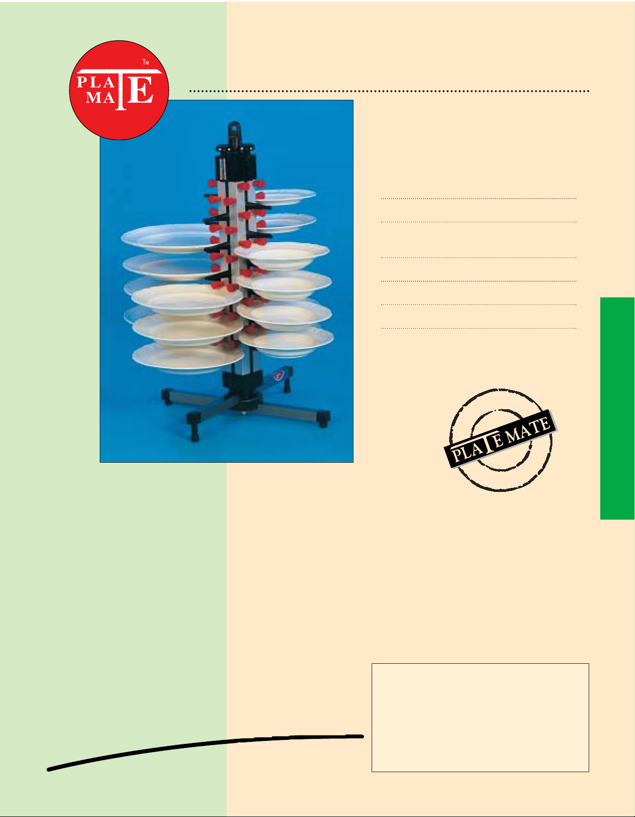
• HOLDING CAPACITY: 24 plates
•TOTAL HEIGHT: 28.7” (73cm)
• MEASUREMENTS OF
UNDERCARRIAGE: 14.2” x 14.2” (36 x 36cm)
• NET WEIGHT: 8.6lb (3.9kg)
• GROSS WEIGHT: 10.1lb (4.6kg)
• BOX: 7.5” x 7.5” x 31.5” (19 x 19 x 80cm)
The table model is a plate stacker for restaurants and other
industrial kitchens, including kitchens on board ship.
The table model is equipped with a suspension eye at the top,
which makes it possible to suspend the device or use it as a wall
model.
The table model is provided with adjustable feet to compensate
for any unevenness in the surface. This model is easy to clean
with a high-pressure washer or with soap suds and a brush.
TM 24 TABLE MODEL - CODE 220
The Product Group, Inc. 1(800) 860-MATE
Canton, Ohio (6283)
TM 24 TABLE MODEL - CODE 220
ASSEMBLY
The table models are delivered in a box and they are for the most part pre-assembled. Only the foot has to be
assembled.
1. Open the box and remove all items. Take the two square tubes with adjustable feet No. T13 and the fastening
block No. T18. Push the tubes at a 90 degree angle into the recessed openings in the fastening block. Push the
tube with the longer feet into the upper opening and the one with the shorter feet into the lower one. Use the
rubber hammer to tap the upper one in.
2. Take the threaded rod No. T12, the nylon bushing No. T24 and the nut T23 (not self-locking). Screw the nut onto
the threaded rod until it is at about 4” (10 cm) from the bottom of the threaded rod.
3. Slide the nylon bushing from the bottom up against the nut. Push the threaded rod through the hole of the two
tubes T13 and the fastening block T18 until the nylon bushing rests on top of the upper tube.
4. Next mount the self-locking nut T22 with the washer T20 on the bottom of the threaded rod. After the nut has
been tightened, the threaded rod should project no more than 1/16” (a couple of millimeters) from the nut.
5. To avoid turning of the threaded rod while the self-locking nut is being mounted, you may want to hold it tight
with a pair of pliers somewhere along its center section.
6. Securely tighten the nut T23 above the nylon bushing. The foot is now fastened. Next place the foot T09 over the
threaded end. The hole in the foot fits over the nylon bushing. Now slide the Plate Mate column over the threaded
end and place the cap with the four adjusting screws on top of the column.
7. Next mount the suspension eye T11 and the hand grip through the eye. The Plate Mate is now ready for use.
The hand grip and the suspension eye can be used to fasten the column in place or rotate it with respect to the
foot. It wheels are desired, they can be mounted; for this option, please order the wheel set WHset code 870.
The set consists of two large and two small wheels. These wheels are provided with a threaded piece that fits into
the insert No. T14. Tighten securely with a 13 mm open-end wrench. To do this, first remove the adjustable feet
T 15/16/17.
Part Name Part No. Quantity
Aluminium main column TK24 1
Adjusting screw 01 4
Plastic hood 02 1
Hoisting block 03 4
Extension 04 4
Bracket set 05 8
Red shuttle 07 48
Corner bracket (left) 08L 4
Corner bracket (right) 08R 4
Plastic foot T09 1
Nylon hand grip T10 1
Suspension eye T11 1
Threaded rod TM24 T12 1
Stainless steel tub
T13 2
Plug-in foot T14 4
Adjusting bolt for foot T15 2
Adjusting bolt for foot T16 2
Spacer for feet T16A 2
Rubber cap T17/06 4
Nylon fastening block T18 1
Steel disc T20 1
Self-locking nut T22 1
Nut T23 1
Spacer internal T24 1
© Copyright 1996 The Product Group, Inc., Patented by H.T.H. b.v.Netherlands
PARTS LIST FOR TM 24 TABLE MODEL
Code 220
 Loading...