

Page 1

Spectroscopic plasma monitor and
PLASUS EMICON MC
Version 3.7
process control systems
User’s Manual
2017
Page 2

Users‘ Manual - 2 - PLASUS EMICON MC
Page 3

© Copyright 2017
PLASUS GmbH
Lechstrasse 9
D-86415 Mering
Germany
Phone: +49 - 8233 - 73 53 78-0
Fax: +49 - 8233 - 73 53 78-9
Internet: www.plasus.de
E-Mail: [email protected]
Users‘ Manual - 3 - PLASUS EMICON MC
Page 4

Users‘ Manual - 4 - PLASUS EMICON MC
Page 5

Table of Contents
Introduction .............................................................................................................................................. 7
System Components ............................................................................................................................... 9
Hardware ............................................................................................................................................. 9
Software ............................................................................................................................................. 10
Optional components ......................................................................................................................... 10
System Requirements ........................................................................................................................ 10
Installation ............................................................................................................................................. 11
Installation of the EMICON software .................................................................................................. 11
Installation of the EMICON hardware ................................................................................................ 11
Installation of optical fibers and collimator optics .............................................................................. 13
Getting Started ...................................................................................................................................... 19
First Measurements ........................................................................................................................... 19
Adjusting signal level ......................................................................................................................... 19
Adding and editing monitor tracks ..................................................................................................... 19
Saving program settings in recipe files .............................................................................................. 20
Saving data ........................................................................................................................................ 20
Replaying data ................................................................................................................................... 20
Reference .............................................................................................................................................. 21
Application Windows .......................................................................................................................... 21
Menu bar and tool bars .................................................................................................................. 21
Spectrum windows ......................................................................................................................... 21
Monitor window .............................................................................................................................. 21
File list ............................................................................................................................................ 21
Recipe list ....................................................................................................................................... 21
System Status ................................................................................................................................ 21
Menu Commands ............................................................................................................................... 23
File Menu ........................................................................................................................................ 23
Plot Menu ....................................................................................................................................... 24
Spectrum Menu .............................................................................................................................. 24
Monitoring Menu ............................................................................................................................. 25
Controlling Menu ............................................................................................................................ 27
View Menu ...................................................................................................................................... 27
Tools Menu ..................................................................................................................................... 28
Window Menu ................................................................................................................................. 28
Help Menu ...................................................................................................................................... 28
Tool Bars ............................................................................................................................................ 29
File .................................................................................................................................................. 29
View ................................................................................................................................................ 29
Plot ................................................................................................................................................. 29
Spectrum ........................................................................................................................................ 29
Monitoring ....................................................................................................................................... 30
Spectrum Data ............................................................................................................................... 30
Monitor Tracks ................................................................................................................................ 30
Controlling ...................................................................................................................................... 30
Users‘ Manual - 5 - PLASUS EMICON MC
Page 6

Dialogs ............................................................................................................................................... 31
Start Options .................................................................................................................................. 31
Monitoring Options ......................................................................................................................... 33
Replay Options ............................................................................................................................... 50
Reference/Calibration/Dark Spectra .............................................................................................. 51
Control Options .............................................................................................................................. 53
Plot Options .................................................................................................................................... 56
Using Settings ................................................................................................................................ 59
Multi-channel Configuration ........................................................................................................... 60
Spectrometer Configuration ........................................................................................................... 60
LAN Control Configuration ............................................................................................................. 61
Profibus Control Configuration ....................................................................................................... 62
SpecLine Configuration .................................................................................................................. 63
Display Settings .............................................................................................................................. 63
Recipe Manager ............................................................................................................................. 64
Control Unit IO-Test ....................................................................................................................... 65
Bug Reports ........................................................................................................................................... 66
Company Information ............................................................................................................................ 68
PLASUS Hotline ................................................................................................................................. 68
PLASUS Address ............................................................................................................................... 68
Version History ...................................................................................................................................... 70
End-User License Agreement for Software (EULA) of PLASUS GmbH ............................................... 72
Users‘ Manual - 6 - PLASUS EMICON MC
Page 7

Introduction
PLASUS EMICON MC
Process control is essential in industrial plasma applications to ensure reliability and high quality of the process.
For this purpose optical emission spectroscopy (OES) is an excellent tool since this technique does not affect the
plasma and several plasma species can be monitored in real-time and in-situ.
The PLASUS EMICON system is designed especially for industrial applications where a robust set-up and easy-to-
use software are required. The standard hardware components of the system are a broad band spectrometer, an
optical fiber and collimator optics. As optional components several D/A-interfaces are available to set up a closed-
loop process control. The PLASUS EMICON software is an easy-to-use Windows
interactively for research purposes as well as stand-alone for process monitoring and controlling. The software can
be configured for the use by technical personal.
Enjoy working with this powerful OES system.
The PLASUS team.
®
software which can be run
Users‘ Manual - 7 - PLASUS EMICON MC
Page 8

Users‘ Manual - 8 - PLASUS EMICON MC
Page 9
System Components
Hardware
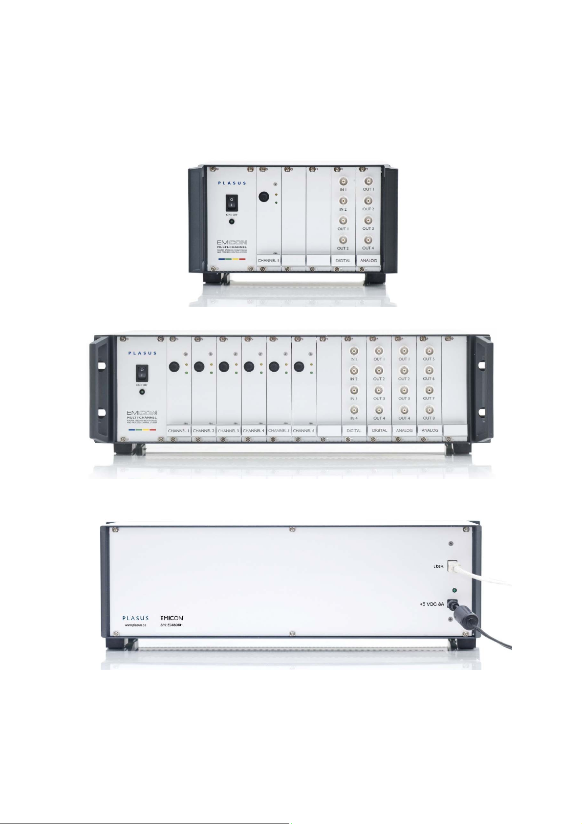
The EMICON system is mounted in a 10” or 19” rack box depending on the number of channels. The spectrometer
channels are on the left hand side and are covered with black caps. The BNC connectors of the digital/analog
control inputs/outputs are located on the right hand side.
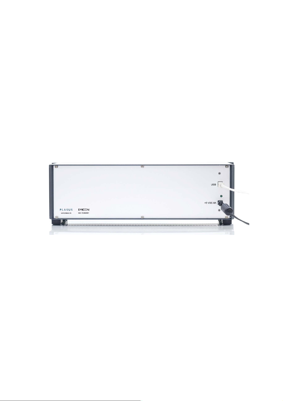
The USB connector and the power supply connector are located on the back side.
- Power supply 5V/4A or 8A
Users‘ Manual - 9 - PLASUS EMICON MC
Page 10

Software
EMICON CD multi-channel application software for Windows® XP/Vista/7/8 (32 and 64 bit).
Optional components
Optics
- optical quartz fibers: for in-vacuum and ex-vacuum use, spectral range UV/VIS/NIR
- collimator optics: for in-vacuum and ex-vacuum use, coating protection spectral range UV/VIS/NIR
- optical vacuum feedthroughs
Software
- Remote Control Library
- PLASUS SpecLine
Please refer to the installation section to install the system.
System Requirements
IBM compatible PC with Pentium processor, CD drive and USB connector
Operating system: Windows
Required free hard disk space: approx. 75 MBytes
®
XP/Vista/7/8 (32 and 64 bit)
Users‘ Manual - 10 - PLASUS EMICON MC
Page 11
Installation
Important: You must install the EMICON software first!
Installation of the EMICON software
Please start the setup from the PLASUS EMICON CD and follow the installation instructions. After the installation
is completed successfully please reboot your system.
After the reboot connect the system to a free USB port and the drivers will be installed automatically. If you are
asked for a driver by the hardware assistant, please choose Install software automatically. Don‘t care about a
missing signature!
Please note: you may be asked for a driver installation as many times as the number of channels of your EMICON
system.
Installation of the EMICON hardware
Electrical connections back side
Plug in the USB cable and the power supply able at the back plate of the system.
All electrical connections are now established and the EMICON system is ready for operation.
Users‘ Manual - 11 - PLASUS EMICON MC
Page 12
Optical fiber connections
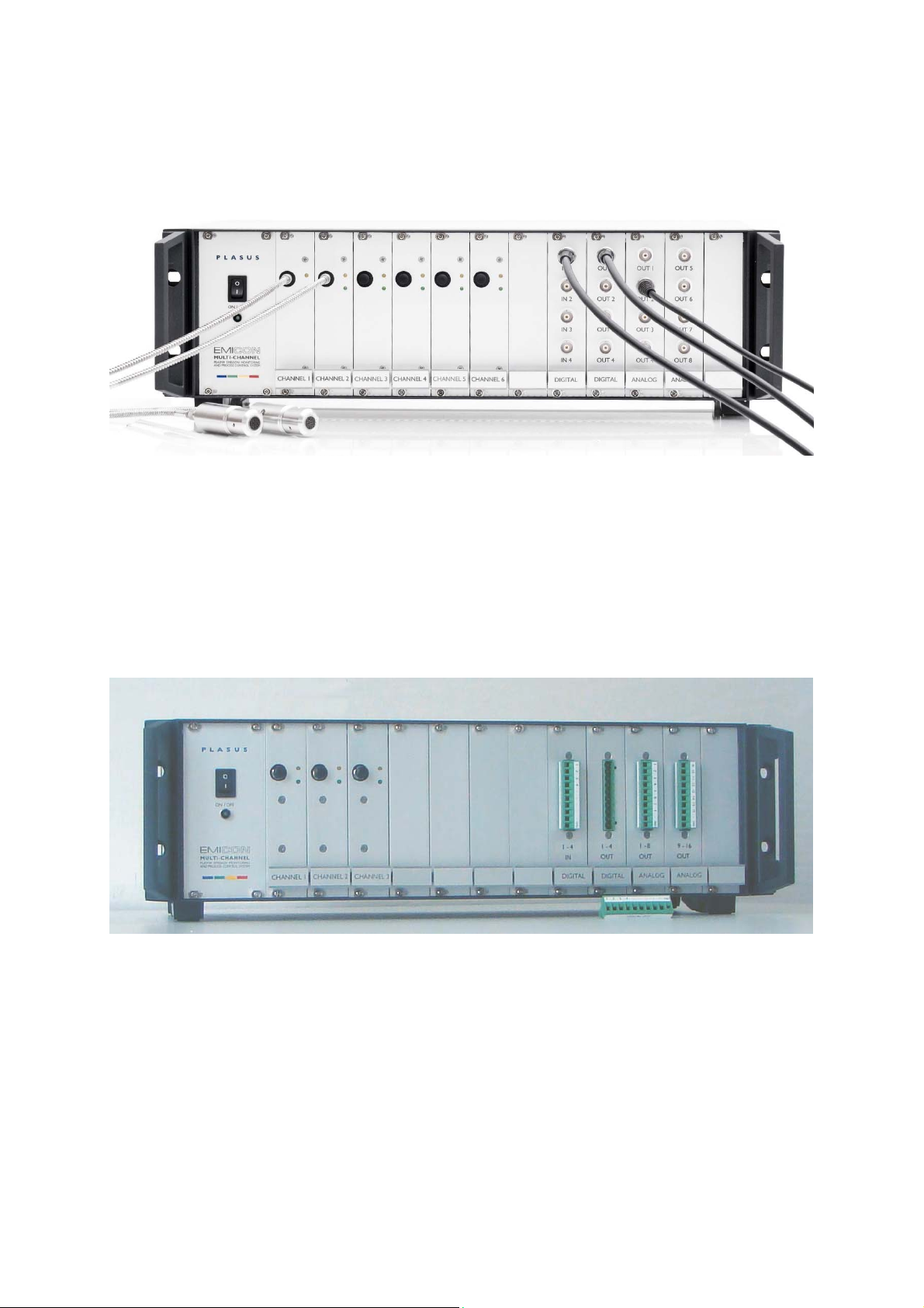
Remove the blue caps from the spectrometer channels at the front plate of the systems and plug in the optical
fibers.
Important: Do not bend the optical fiber sharply!
Electrical connections front side
For controlling purposes connect the digital inputs/outputs and analog outputs (BNC). The digital inputs are used
for incoming trigger signals, the digital outputs for outgoing trigger signals. The analog outputs can are used for
process monitoring and controlling.
Please refer to the appropriate section in this manual for the assignment of the inputs and outputs.
EMICON system with electrical connector bars
In case the EMICON system is equipped with electrical connector use the terminal bars for connecting the digital
and analog inputs and outputs
Users‘ Manual - 12 - PLASUS EMICON MC
Page 13
Installation of optical fibers and collimator optics
Important: Do not bend sharply the optical fibers!
Ex-Vacuum optics
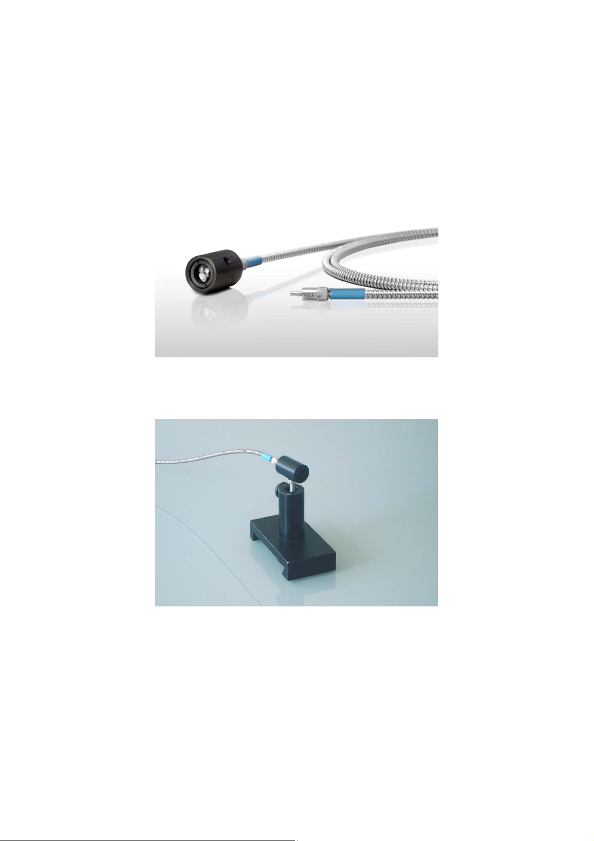
The ex-vacuum optics consists of
- optical fiber (blue jacketing) and
- optical sensor head (black).
Please connect one side of the optical fiber to the SMA connectors of a spectrometer channel of the EMICON
system and the other side to the collimator optics. Place the collimator optics in front of a viewport of your application
through which the plasma light is visible. The optical sensor head should face the plasma light which is to be
monitored. You may use the M6 thread on the side of the sensor head to fix the head.
Important: Do not touch the lens in the optical sensor head!
The collimator optics collects all radiation from the direction of the line of sight. The line of sight can be considered
as an endless tube with a diameter of about 10 mm emerging from the top of the collimator optics. Adjust the line
of sight of the collimator optics to the volume you want to observe just like you would do with a telescope.
Please keep in mind that optical emission spectroscopy is a line integrating method and therefore all radiation along
the line of sight of the collimator optics is accumulated.
In order to detect light in the wavelength region below 400 nm you must use a quartz window for the viewport of
your application.
Users‘ Manual - 13 - PLASUS EMICON MC
Page 14
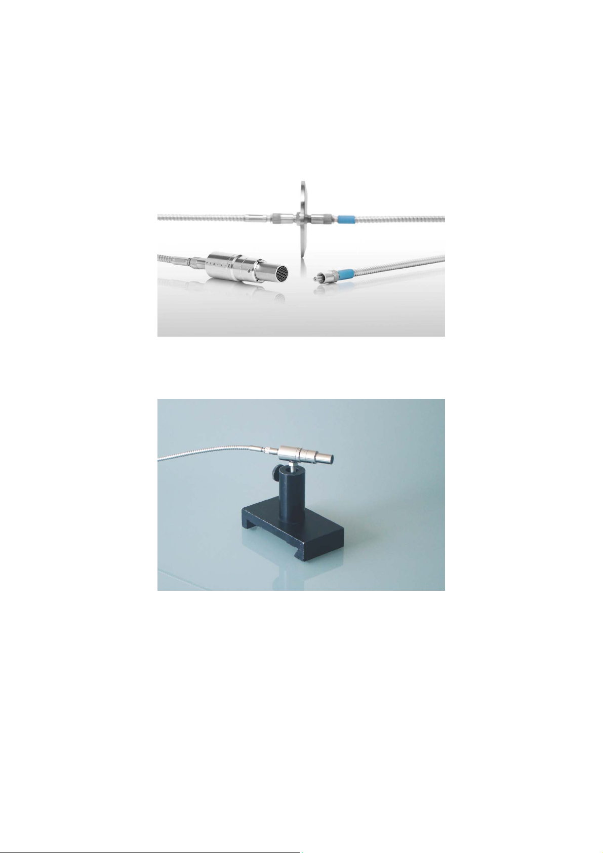
In-Vacuum optics
The in-vacuum optics consists of
- in-vacuum optical head with collimator optics and coating protection device (stainless steel)
- in-vacuum optical fiber (stainless steel jacketing)
- optical vacuum feed-through (in a KF/CF ISO flange)
- optical fiber for ex-vacuum use
The optical should face the plasma light which is to be monitored. You may use the M6 thread on the side of the
collimator optics to fix the head. If you are not using the M6 tread please close it with the supplied screw to protect
the inside of the optical head from coating.
Important: Do not touch the lens in the optical sensor head!
The collimator optics collects all radiation from the direction of the line of sight. The line of sight can be considered
as an endless tube with a diameter of about 10 mm emerging from the top of the optical head. Adjust the line of
sight of the optical head to the volume you want to observe just like you would do with a telescope.
Please keep in mind that optical emission spectroscopy is a line integrating method and therefore all radiation along
the line of sight of the optical is accumulated.
Users‘ Manual - 14 - PLASUS EMICON MC
Page 15
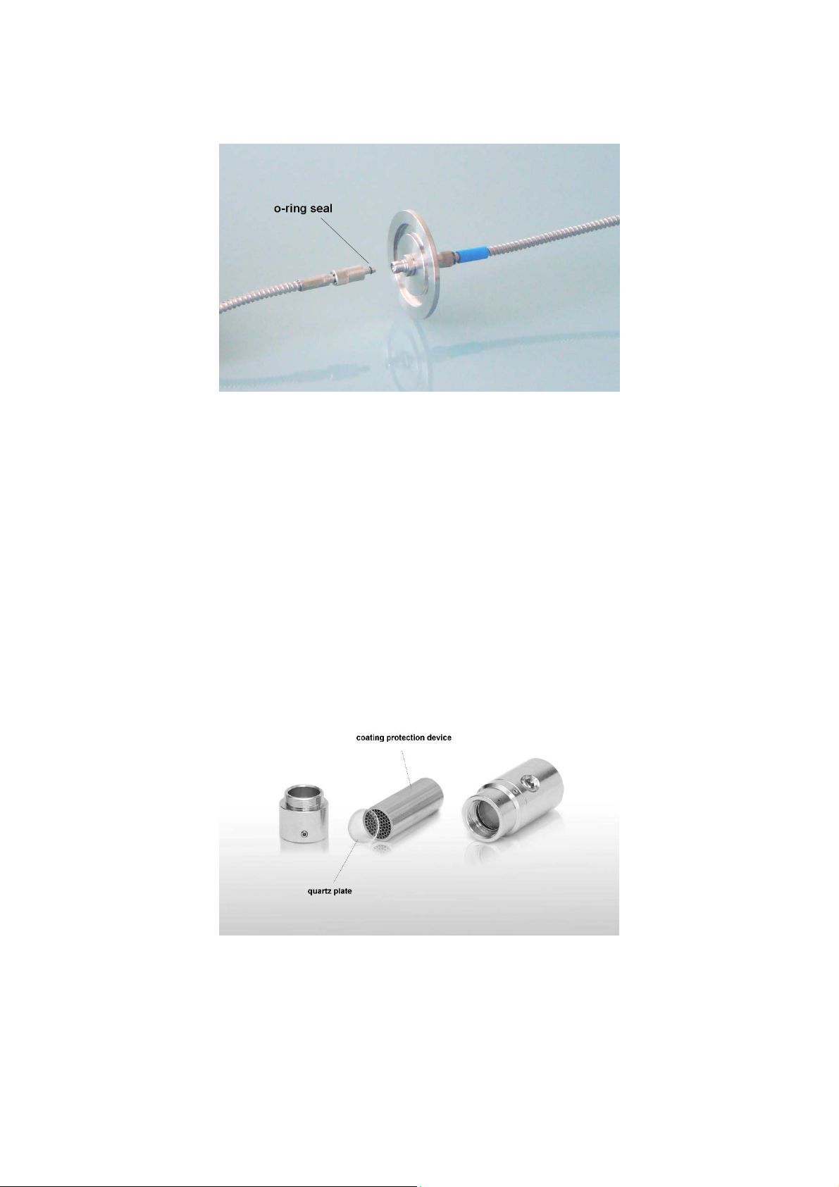
Connect one side of the in-vacuum optical fiber to the optical head and the other side to the vacuum feed-through
(vacuum side!).
Depending on your vacuum chamber design you may first connect the in-vacuum optical fiber to the vacuum feedthrough and then assemble the vacuum feed-through to the vacuum chamber.
On delivery the SMA connectors on either side of the in-vacuum optical fiber are equipped with o-ring seals allowing
either side to be connected to the vacuum feed-through. However, if you need to change an o-ring seal remove the
old o-ring carefully from the tip of the SMA connector and pull over the new o-ring. Make sure that the tip of the
SMA connector will not be damaged!
The optical vacuum feedthroughs are integrated in an ISO KF or CF flange. Assemble the KF/CF flange to the
vacuum chamber.
Connect the optical fiber for ex-vacuum use to the optical vacuum feed-through on one side and to a spectrometer
channel of the EMICON system on the other side.
If you need to change the coating protection (quartz plate or capillary cartridge) in the protection device holder in
front of the optical head, please unscrew the complete front part of the head which holds the coating protection
devices. The protection device will fall off when loosening the small screws on the side of the cylinder.
Important: Do not touch the lens in the optical sensor head!
Users‘ Manual - 15 - PLASUS EMICON MC
Page 16
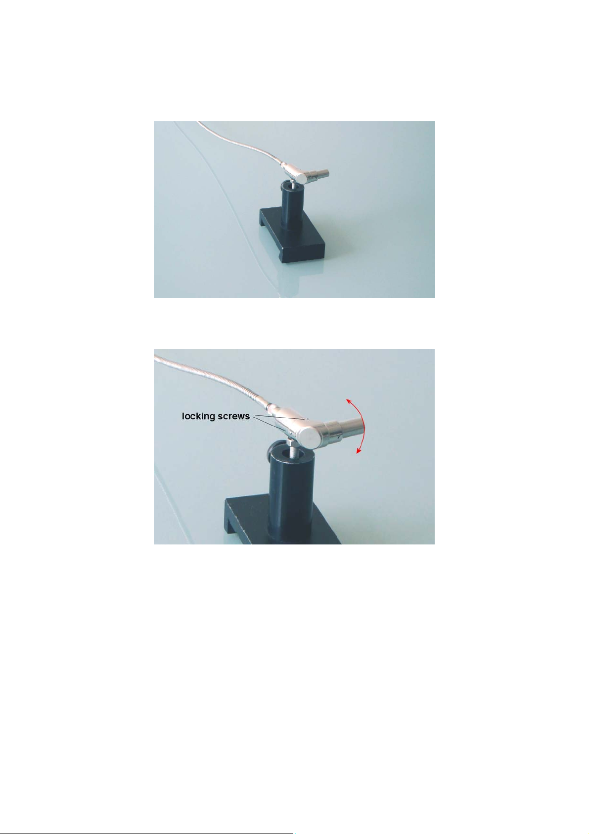
The 90° version of the in-vacuum optical head is mounted similar to the standard version:
The optical head should face the plasma light which is to be monitored. You may use the M6 thread on the side of
the sensor head to fix the head. If you are not using the M6 tread please close it with the supplied screw to protect
the inside of the optical head from coating.
In order to adjust the line of sight of the optical head the top part of the optical head can be rotated: Loosen the
three screws at the bottom of the 90° degree converter. Now, you can rotate the upper part of the sensor. Adjust
the line of sight and tighten the screws again.
Important: Do not touch the mirror and the lens in the optical sensor head!
Users‘ Manual - 16 - PLASUS EMICON MC
Page 17

If you need to change the coating protection (quartz plate or capillary cartridge) in the protection device holder in
front of the optical head, please unscrew the complete front part of the head which holds the coating protection
devices. The protection device will fall off when loosening the small screws on the side of the cylinder.
Important: Do not touch the mirror and the lens in the optical sensor head!
Users‘ Manual - 17 - PLASUS EMICON MC
Page 18

Users‘ Manual - 18 - PLASUS EMICON MC
Page 19

Getting Started
First Measurements
After the successful hardware and software installation of the EMICON system start the EMICON software on the
computer. In the Start Options dialog you must specify an operation mode:
Recording mode: Standard data acquisition
Replay mode: Replay already recorded data.
Choose Recording Mode and Default recipe file and push the OK button.
The EMICON system is now initialized which may take several seconds. The more spectrometer channels are
installed the longer the initialization time. After a successful initialization the main application windows are displayed:
the file list and recipe list on the left side and the spectrum and monitor windows on the left. There are as many
spectrum windows as spectrometer channels installed in the system.
The spectrum windows are displaying the currently acquired spectra of each spectrometer channel. The monitor
window shows the temporal evolution of the monitor tracks.
Start the measurement by selecting either the menu command Monitoring | Start Monitoring or by pushing the tool
bar button . The spectra in the spectrum windows and the and intensities of the monitor tracks in the monitor
window are now continuously updated. Stop the measurement by selecting either the menu command Monitoring |
Stop Monitoring or by pushing the tool bar button .
Adjusting signal level
Depending on the light intensity of your application the signal level of the recording must be adjusted. This is done
by changing the integration time in the Monitoring Options dialog (→ Monitoring Options | Recording | Integration
time): The longer the integration time the more light intensity is collected and the higher the signal level. The perfect
value for the integration time is if the strongest line in the spectrum is just below the maximum signal level, i.e.
65536 for 16 Bit A/D signal conversion and 4096 for 12 Bit A/D signal conversion.
Please consider the following cases:
A. Low signal levels
In the spectrum only a few lines with very little signal can be identified: The integration time is too small. For a better
signal level increase the integration time.
B. Saturated signal levels
In the spectrum several lines have a flat top at the maximum signal level: The lines are so called “saturated”, which
means that the light intensity is too strong for the detector. Decrease the integration time until all lines are no longer
saturated.
Please note: The recording time which is the time between two consecutive spectrum acquisitions must be longer
or equal to the integration time. If necessary, you will be asked to adjust the recording time in the Monitoring Options
dialog (→ Monitoring Options | Recording | Recording time).
Adding and editing monitor tracks
On first start up of the EMICON system one monitor track per spectrum window is set-up at a random wavelength.
For changing the wavelength position of the monitor track select the monitor track in the spectrum window by mouse
clicking on the rectangle of the line marking. The solid line marking will change to a dashed line marking and now
the position of the line marking can be changed with the mouse or by using the arrow keys of the keyboard. The
selection of the monitor track is cleared by pressing the ESC key.
If you want to add a monitor track activate the spectrum window and select either the menu command Spectrum |
Add line or use the tool bar button . A cross hair cursor will appear in the activated spectrum window which
should be moved to the wavelength position of the new monitor track. When placing the cursor at the desired
wavelength position with a mouse click, you will be asked to input a track name for the new monitor track. On
confirmation the new monitor track is added to the monitor window and the track name will appear in the file list.
Users‘ Manual - 19 - PLASUS EMICON MC
Page 20

If you want to add an integral (wavelength range) as monitor track select the either the menu command Spectrum
| Add integral or use the tool bar button . A range cursor will appear in the activated spectrum window which
should be moved to the wavelength position of the new monitor track. After placing the cursor to the desired
wavelength position and specifying the track name the limits of the integral can be changed either with the mouse
or by using the arrow keys while pressing “l” for the left limit and “r” for the right limit.
If you want to remove monitor track select the track in the file list and either use the menu command Spectrum |
Delete line/ integral or use the tool bar button or push the DEL key on the keyboard.
For combining already existing monitor tracks activate the monitor window and select the either the menu command
Monitoring | Add combined monitor track or use the tool bar button . The dialog Combing Monitor Tracks will be
opened where you can select from the already existing monitor tracks and the type of operation.
Saving program settings in recipe files
The set of program settings and selection of program options is called recipe. The recipe contains all information
about the recording, the data saving, the monitor tracks, the data evaluation, etc..
A recipe is saved by selecting the menu command Monitoring | Save current recipe… . In specified recipe all current
program settings are saved. The recipe can be loaded again by either selecting the option Ask for recipe in the Start
Options dialog or by selecting the menu command Monitoring | Load recipe file/list.
The concept of recipes allows you change easily and quickly between different processes and applications.
Saving data
The recorded data is saved in spectrum files and monitor data files. The spectrum files (.txt) consist of the recorded
spectrum (wavelength - intensity values) of a specific recording time. In the monitor data files (.ecf) the temporal
evolution of the intensity of the monitor tracks are saved. All data is save in ASCII.
For switching on data saving open the tab sheet Data Storage in the Monitoring Options dialog. Select your choice
which data should be saved to hard disk and specify the root folder name and the root file names for the monitor
data and for the spectra.
Please note: If you want to perform a replay of your recorded data you must save the spectrum files.
Replaying data
For an offline analysis of recorded data the replay mode is available. The replay mode is started by opening a new
monitor file (File | New | Monitor or ). The Start Options dialog is opened in which you select Replay mode.
During the initialization of the replay mode you will be asked for the sequence of spectrum files to be replayed.
Navigate to the folder where you have saved the spectrum files and select the spectrum channel which you want
to replay.
You may now replay your data with different monitor settings as often as you like. Except for the online features
“Recording”, “Triggering” and “Controlling” all functions of the recording mode are available.
You can change back to real-time recording by opening a new monitor file (File | New | Monitor or ) and selecting
Recording Mode in the Start Options dialog.
Please note: The recording mode and the replay mode cannot run at the same time.
Users‘ Manual - 20 - PLASUS EMICON MC
Page 21
Reference
Application Windows
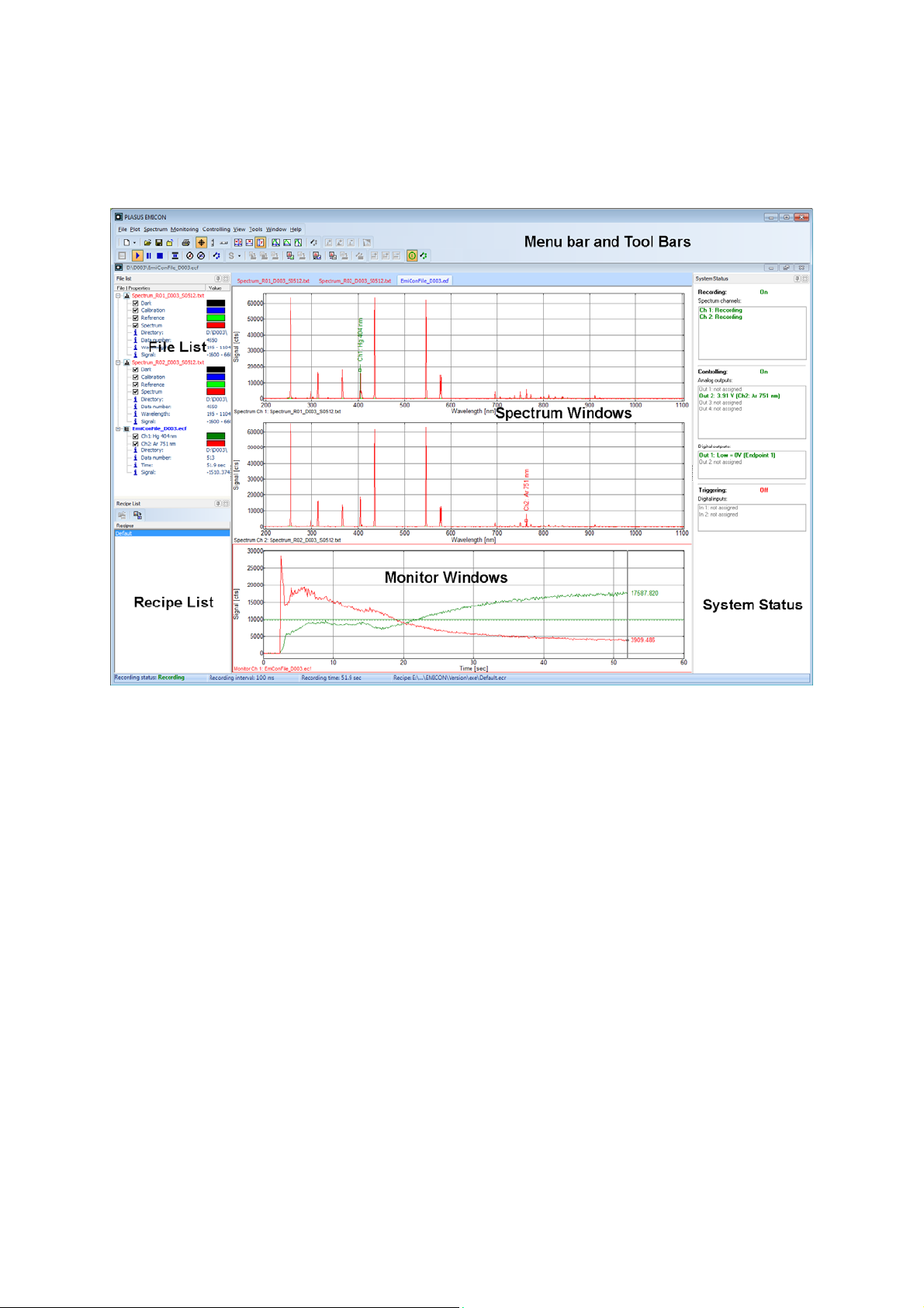
The application window of the EMICON software is divided in the following windows:
Menu bar and tool bars
This is the main window of the application which appears after starting the program. The menus and toolbars contain
all commands available as it is common in Windows
Spectrum windows
While recording this window displays the currently acquired spectrum as well as the background and reference
spectrum. Lines and integrals are indicated and you may add, change or delete those lines and integrals for
monitoring or evaluation purposes.
Monitor window
In the monitor window the time tracks of the intensities of selected lines and integrals are displayed. Tracks can be
added by selecting a line or integral in the Record/Spectrum window and by carrying out the command Add
line/integral as monitor track.
File list
The file list is a summary of all spectra and monitor tracks in the spectrum and monitor windows. The check box in
front of each spectrum/track indicates whether it is visible or hidden. The check box of the currently selected
spectrum/track is displayed in red and the background color of the track name is highlighted.
Pressing the right mouse button above a track or file name will open up a menu with commands available for that
track or file.
Recipe list
The recipe list is a summary of the loaded recipes. The currently selected and active recipe is displayed in the
status bar at the button of monitor window. Switching to a another recipe can be done by double clicking on the
recipe name or by using the tool bar command.
System Status
The system status window displays the current status of all system components as spectrometer channels, digital
input and outputs and analog outputs.
®
applications.
Users‘ Manual - 21 - PLASUS EMICON MC
Page 22

Users‘ Manual - 22 - PLASUS EMICON MC
Page 23

Menu Commands
File Menu
New monitor
Create and open mew monitor configuration
Open ...
Open a spectrum or an existing an EMICON File (.ecf).
Save
Save the data of the active window in ASCII format. You will be asked which spectra or time tracks you want to
save.
Close
Close the active window with all spectra and/or EMICON Files.
Print...
Print the active window. For the setting up the printer please refer to the options section in the printer set-up.
Start options ...
Open the dialog for changing the start options.
Configure ►
Configure general settings.
Start options
Operation mode ►
Select the operation mode and configure the user mode.
Administrator mode
User mode
User setting
Changing between administrator and user mode requires a password. The default password is admin.
If you don‘t remember your password copy the default administration file “admin“ from the installation CD in the
program folder.
Exit
Close the EMICON application stopping all recording processes.
Users‘ Manual - 23 - PLASUS EMICON MC
Page 24
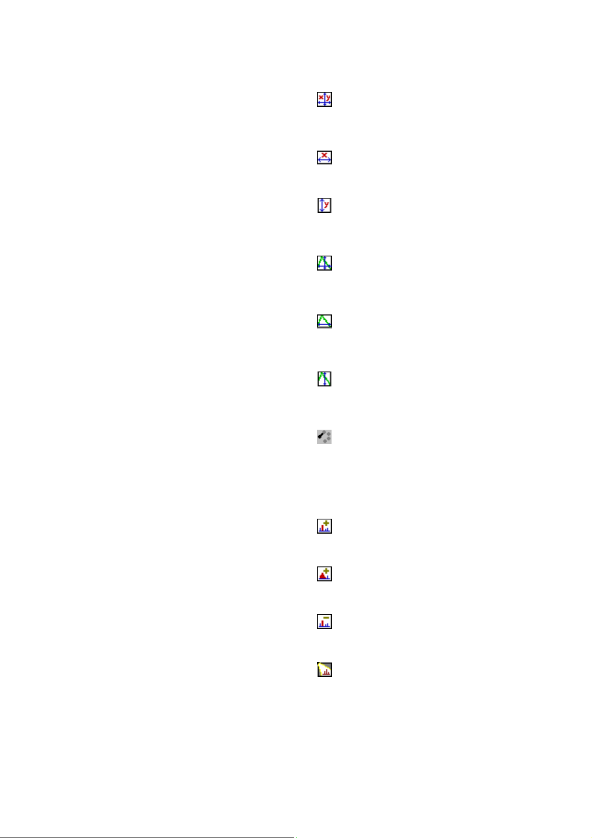
Plot Menu
XY-Autoscale
Set the display ranges of the wavelength/time and of the signal to the minimum and maximum data values of the
selected file.
This will display all data of the selected file.
X-Autoscale
Set the display range of the wavelength/time to the minimum and maximum data values of the selected file.
The display range of the signal remains unaffected.
Y-Autoscale
Set the display range of the signal to the minimum and maximum data values within the displayed wavelength/time
range of the selected file.
The display range of the wavelength/time remains unaffected.
XY-Autoscale single track
Set the display ranges of the wavelength/time and of the signal to the minimum and maximum data values of the
selected spectrum/track.
This will display all data of the selected track.
X-Autoscale single track
Set the display range of the wavelength/time to the minimum and maximum data values of the selected
spectrum/track.
The display range of the signal remains unaffected.
Y-Autoscale single track
Set the display range of the signal to the minimum and maximum data values within the displayed wavelength/time
range of the selected spectrum/track.
The display range of the wavelength/time remains unaffected.
Configure plot ...
Open the dialog for setting up or changing the plot options.
Spectrum Menu
Add line
Add a line to the selected spectrum.
This line may be used for monitoring the time dependency of the intensity.
Add integral
Add a line integral to the selected spectrum.
This line integral may be used for monitoring the time dependency of the intensity.
Delete line/integral
Delete selected line or line integral.
If this line or line integral was connected to a monitor track the corresponding monitor track will be deleted as well.
Open spectrum with SpecLine
The currently displayed spectrum of the selected spectrum window is opened in the SpecLine software for further
analysis.
This function is available only if the Plasus SpecLine is installed on the computer!
Users‘ Manual - 24 - PLASUS EMICON MC
Page 25

Monitoring Menu
(Available only in configuration type “Monitor”)
New monitor
Create a new monitor file.
Start monitoring
Start monitoring.
Pause monitoring
Pause monitoring. While pausing monitoring the recording of spectra will continue. Monitoring time is suspended
until pausing is turned off.
Stop monitoring
Stop monitoring.
If the option Synchronize recording with monitoring is selected in the dialog Monitor Options recording will stop as
well.
Auto pause monitor
Switch on/off automatic pausing of monitoring for low light intensity. The intensity threshold must be set in the
dialog Monitoring Options.
Suspend spectrum display
Suspend spectrum display while recording data.
Since updating the display consumes a lot of CPU time this option may be helpful for measurements in which time
s critical.
Suspend monitor display
Suspend monitor display while recording data.
Since updating the display consumes a lot of CPU time this option may be helpful for measurements in which time
is critical.
Configure monitoring
Open the dialog for setting up and changing the recording options.
Recording Mode ... ►
Spectrum Mode
Switch to spectrum mode for recording and evaluating spectra.
Transmission Mode
Switch to transmission mode for recording and evaluating spectra.
Reflection Mode
Switch to reflection mode for recording and evaluating spectra.
Absorbance Mode
Switch to absorbance for recording and evaluating spectra.
Users‘ Manual - 25 - PLASUS EMICON MC
Page 26

Reference spectrum ... ►
Subtract reference sp ectrum
Switch on/off automatic subtraction of reference spectrum while recording.
Take current spectrum as reference spectrum
Set current spectrum as reference spectrum.
Open reference spectrum fro m file
Load a reference spectrum from hard disk.
Save reference spectrum to file
Save reference spectrum to hard disk.
Clear reference spectrum
Clear the reference spectrum. All signal values are set to zero.
Intensity Calibration ... ►
Apply intensity calibration
Switch on/off intensity calibration using calibration spectrum while recording.
Take current spectrum a s calibration spectrum
Set current spectrum as calibration spectrum.
Open calibration spectrum from file
Load a calibration spectrum from hard disk.
Save calibration spectrum to file
Save calibration spectrum to hard disk.
Clear calibration spectrum
Clear the calibration spectrum. All signal values are set to one.
Background spectrum ... ►
Subtract background spectrum
Switch on/off automatic subtraction of background spectrum while recording.
Take current spectrum as background spectrum
Set current spectrum as background spectrum.
Open background spectrum from file
Load a background spectrum from hard disk.
Save background spectrum to file
Save background spectrum to hard disk.
Clear background spectrum
Clear the background spectrum. All signal values are set to zero.
Configure record files
Open the dialog for setting up and changing the record file options.
Add line/integral as monitor track
Add selected line or line integral as monitor track.
Add evaluation or combined monitor track
Add monitor track for evaluation or as a combination of two already existing monitor tracks.
The tracks can be combined by basic arithmetical operations.
Delete monitor track
Delete selected monitor track.
Open recipe file/list
Open and load recipe file or recipe list with recording, monitoring and controlling settings from hard disk.
Save current recipe file as default
Save all current recording, monitoring and controlling settings to the default recipe file on hard disk.
Save current recipe file as …
Save all current recording, monitoring and controlling settings to recipe file with specified file name on hard disk.
Users‘ Manual - 26 - PLASUS EMICON MC
Page 27

Controlling Menu
Controlling on/off
Switch on/off controlling.
Voltage output on/off
Switch on/off the voltage output for all digital and analog outputs. This switch does not affect the control settings it
only deactivates or activates the actual output.
Configure controlling …
Open the dialog for setting up and changing the control parameters.
Configure response curves …
Open the dialog for setting up and changing the response curve parameters.
View Menu
Line cursor
Switch on/off line cursor.
Horizontal scrollbar
Switch on/off horizontal scroll bar.
Vertical scrollbar
Switch on/off vertical scroll bar.
File list
Display/hide file list window.
Recipe list
Display/hide file recipe list window.
Tool Bars ►
Show/hide the following tool bars:
- File
- View
- Plot
- Spectrum
- Monitoring
- Spectrum Data
- Monitor Tracks
- Controlling
Users‘ Manual - 27 - PLASUS EMICON MC
Page 28

Tools Menu
Recipe Manager ►
Open recipe manager
Open the recipe manager which is an independent program for editing recipe lists.
System configuration ►
Configure multi-channel monitor …
Open the dialog for configuring a multi-channel monitor
Configure spectrometer cha nnels …
Open the dialog for configuring the spectrometer channels
Select main system
Open the dialog for selecting an EMICON system, if more than one EMICON system is connected to the
Select control unit
Remote control ►
Configure …
SpecLine ►
Configure
Window Menu
All windows are listed and can be selected.
Help Menu
EMICON Help Index
The index of the help system for EMICON is displayed.
PLASUS Homepage
Link to PLASUS Homepage. Please check for news and latest updates.
Info about EMICON …
Information (serial number, copyright, etc.) about the EMICON software is displayed.
computer
Open the dialog for checking and selecting the control unit of the EMICON system
Open the dialog for configuring the remote control connection.
(Available only if Data Exchange Library is installed.)
Open the dialog for setting up configuring the interface with the Plasus SpecLine software.
Users‘ Manual - 28 - PLASUS EMICON MC
Page 29

Tool Bars
In the tool bars the most important and often used menu commands are displayed as buttons. By pressing a button
the corresponding menu command is carried out.
File
This tool bar contains the follow buttons:
Button Action
Create a new record or monitor window
Open an existing spectrum or EMICON File (.ecf)
Save the data of the active window in ASCII format
Close the active window with all spectra and/or ECF files
Display the index of the EMICON help system
Print the active window
View
This tool bar contains the follow buttons:
Button Action
Switch on/off line cursor
Switch on/off horizontal scrollbar
Switch on/off vertical scrollbar
Plot
This tool bar contains the follow buttons:
Button Action
Autoscale display ranges for x and y of the selected file
Autoscale display range for x of the selected file
Autoscale display range for y of the selected file
Autoscale display ranges for x and y of the selected track
Autoscale display range for x of the selected track
Autoscale display range for y of the selected track
Open dialog for setting up and changing plot options
Spectrum
This tool bar contains the follow buttons:
Button Action
Add a line to the selected spectrum
Add a line integral to the selected spectrum
Delete selected line or line integral
Open current spectrum in PLASUS SpecLine software
(Available only if SpecLine software is installed!)
Users‘ Manual - 29 - PLASUS EMICON MC
Page 30

Monitoring
Button Action
Create a new monitor window
Start monitoring
Pause monitoring
Stop monitoring
Switch on/off automatic pausing of monitoring for low light intensity. The intensity threshold must
be set in the dialog Monitoring Options
Suspend spectrum display while recording data
Suspend monitor display while recording data
Open dialog for setting up and changing monitor options
Spectrum Data
This tool bar contains the follow buttons:
Button Action
Switch to spectrum / transmission / reflection / absorbance mode for recording and evaluating
spectra.
Save the current spectrum while recording (save on demand only)
Start saving the spectrum awhile recording (save on demand only)
Stop saving the spectrum awhile recording (save on demand only)
Switch on/off intensity calibration using calibration spectrum
Switch on/off automatic background subtraction
Take current spectrum as reference spectrum
Switch on/off automatic subtraction of reference spectrum
Take current spectrum as reference spectrum
Open dialog for setting up and changing record files options
Monitor Tracks
Add selected line or line integral as monitor track
Add monitor track as evaluation or combination of two already existing monitor tracks
Delete selected monitor track
Controlling
This tool bar contains the follow buttons:
Button Action
Switch on/off controlling
Open dialog for setting up and changing control parameters
Users‘ Manual - 30 - PLASUS EMICON MC
Page 31
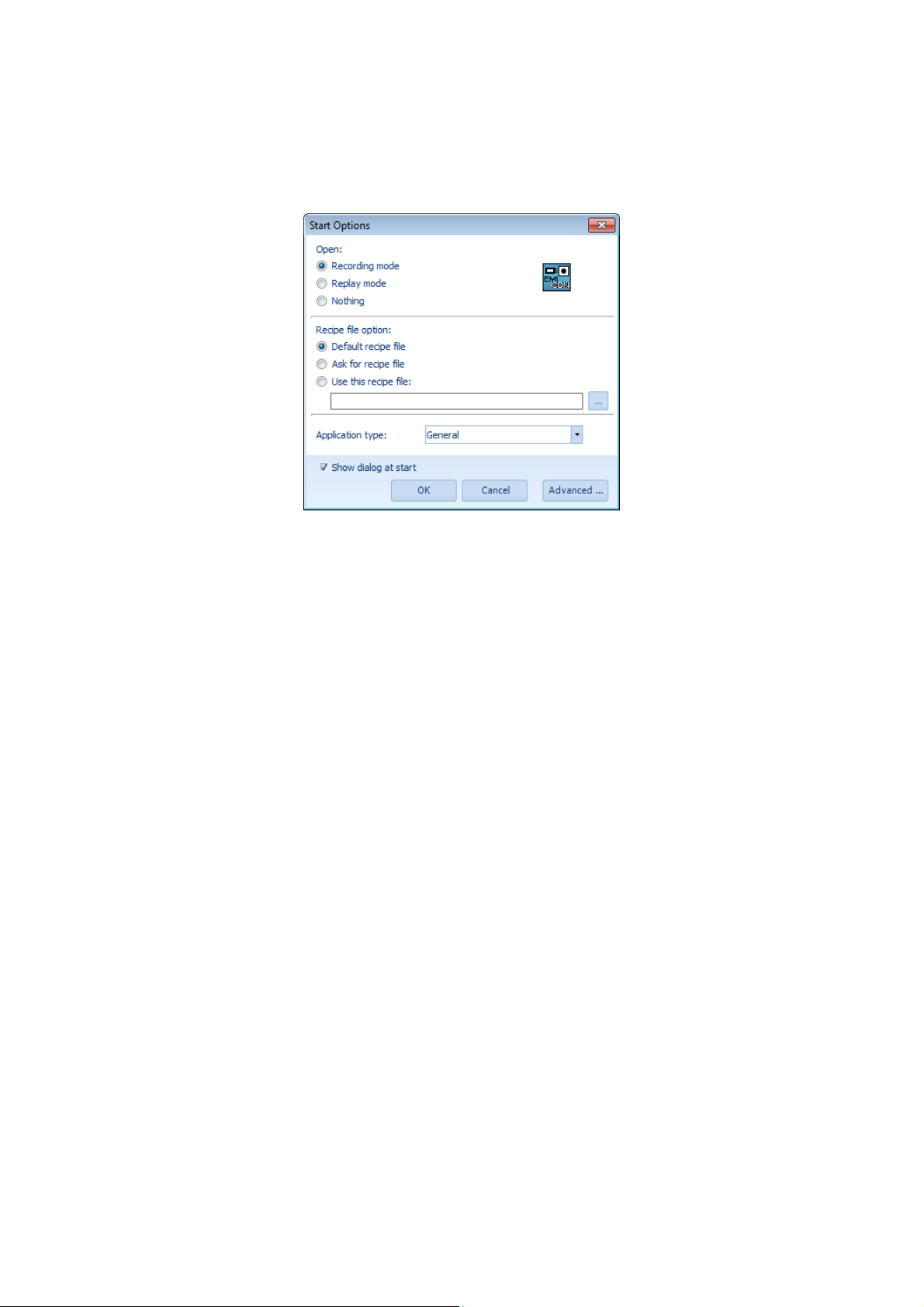
Dialogs
Start Options
Dialog for setting and changing the start options:
Open:
Recording mode
Replay mode
Nothing
Recipe file option:
Default recipe file
Ask for recipe file
Use this recipe file:
Application type:
Show dialog at start
Data acquisition with connected hardware
Replaying of recorded data
Nothing
Use default recipe file
Select a recipe file
Use given recipe file
For several types of applications program settings are predefined
(Default: General)
Show Start Options dialog at start of program
Users‘ Manual - 31 - PLASUS EMICON MC
Page 32
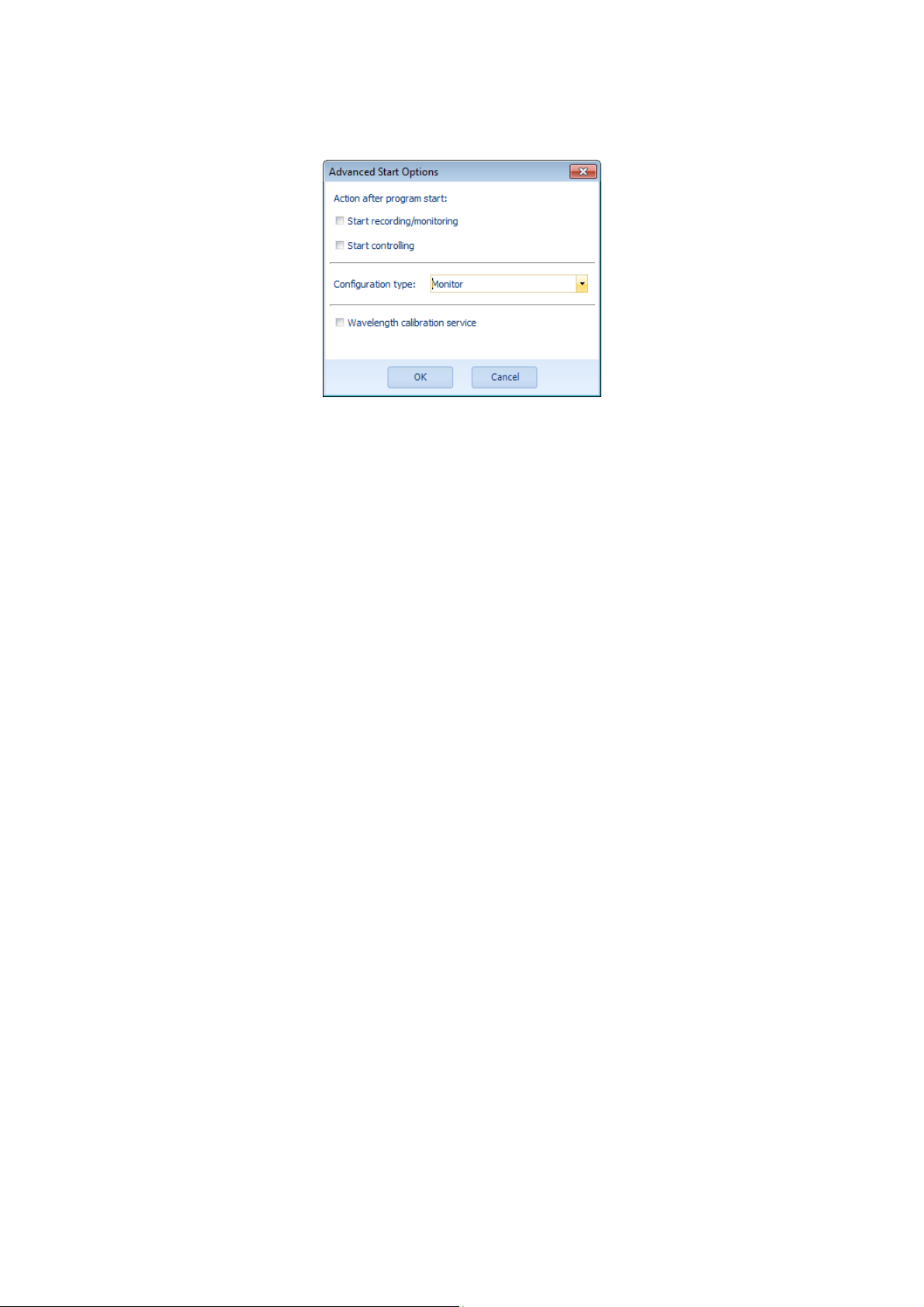
Advanced Start Options
Action after program start:
Start recording/monitoring
Start controlling
Configuration type
Wavelength calibration service
Recording/Monitoring is launched automatically after program
start
Controlling is launched automatically after program start
Choose type of configuration: Only Monitor is available
Must be activated when a wavelength calibration service is carried
out
Users‘ Manual - 32 - PLASUS EMICON MC
Page 33
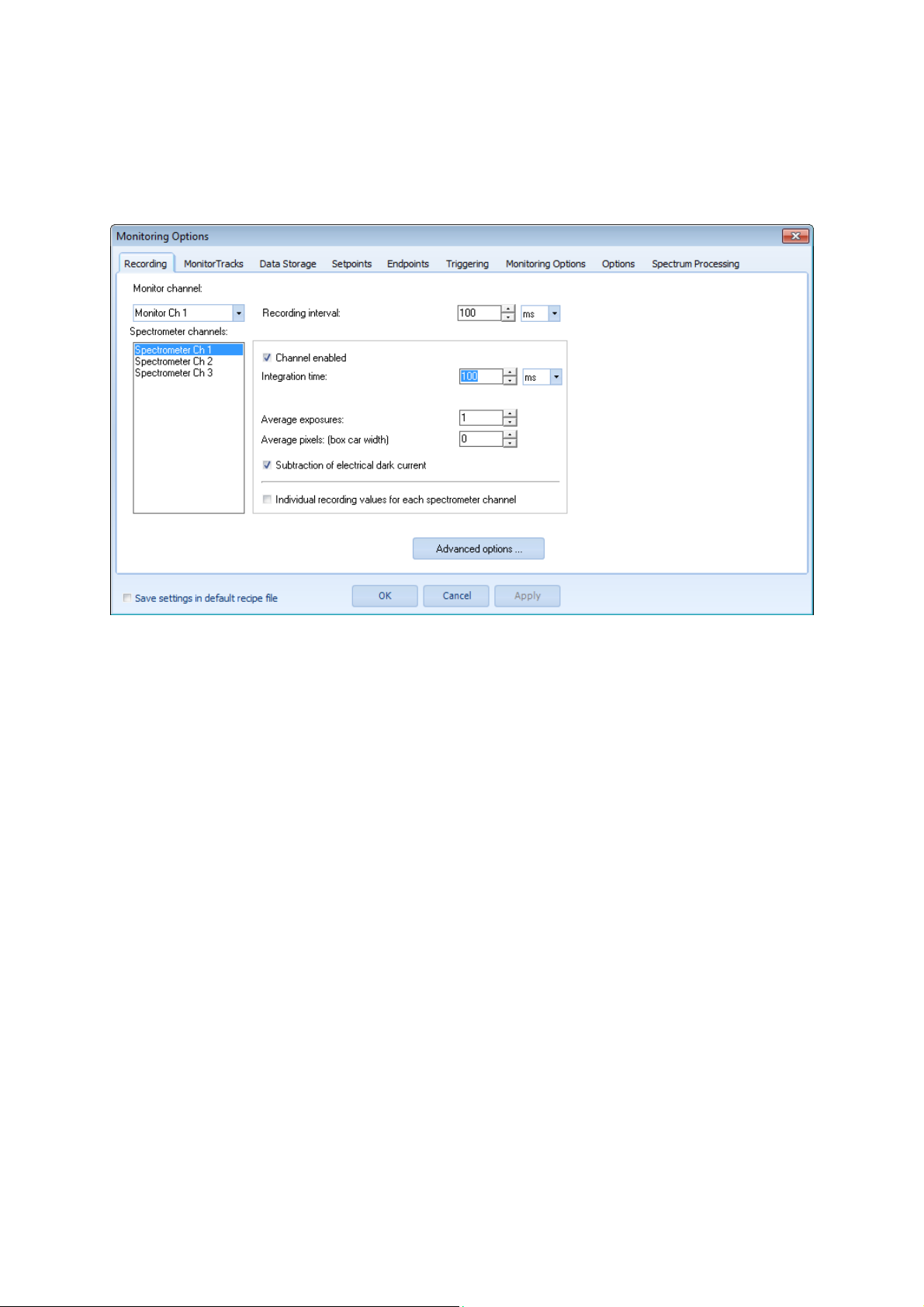
Monitoring Options
Dialog for setting and changing monitoring options with the following tab sheets:
Recording
(Multi-Channel System)
Monitor channel:
Recording interval:
Spectrometer channels:
Channel enabled
Integration time:
Average exposures:
Average pixels:
Subtraction of electrical dark current
Individual recording values for each
spectrometer channel
General:
Default values
All settings apply to the selected monitor channel
Interval between consecutive exposures
All settings apply to the selected spectrometer channel
Enable/disable selected spectrometer channel
Integration time of single exposure
Average over the given number of exposures
Average over the given number of pixel
(spectral mean average value, box car width)
Automatic correction of electrical dark of the diode array
Allow individual values for each spectrometer channel
The current recipe settings are saved in the default recipe
Users‘ Manual - 33 - PLASUS EMICON MC
Page 34
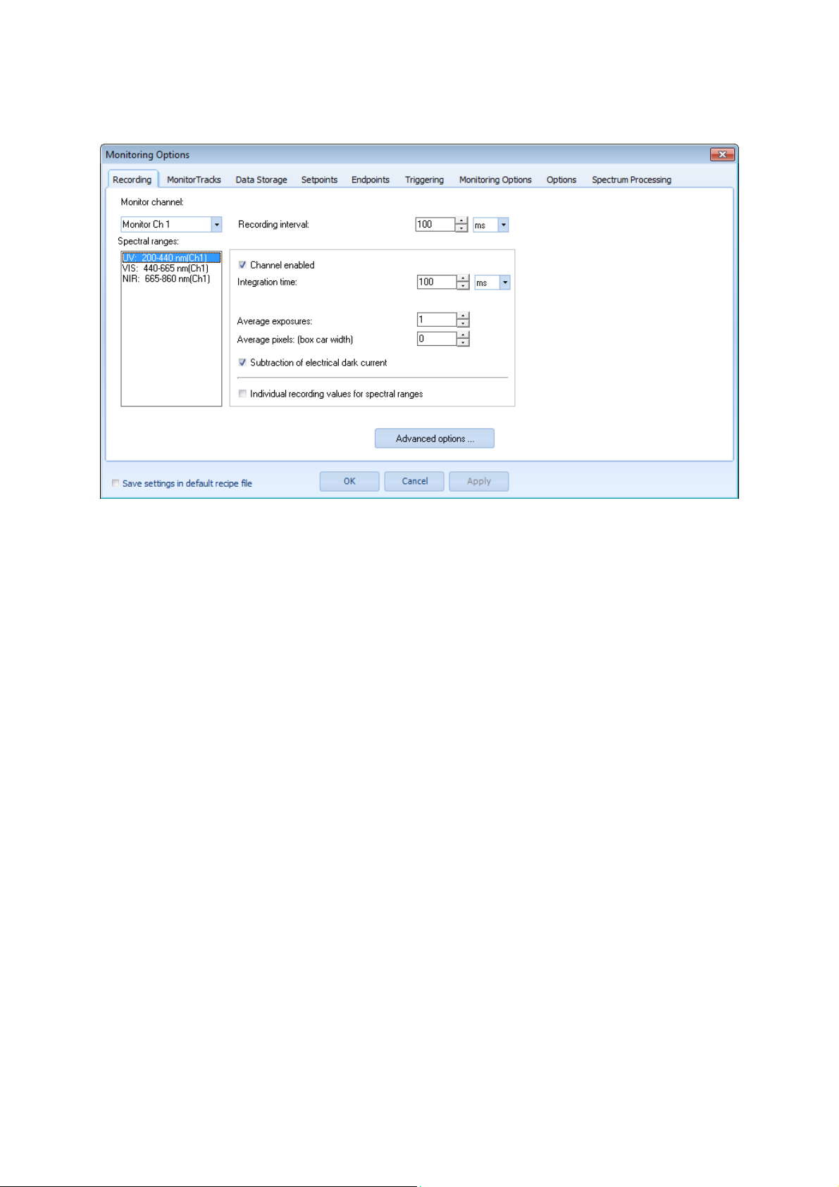
Recording
(High-Resolution System)
Monitor channel:
Recording interval [ms]:
Spectral ranges:
Channel enabled
Integration time:
Average exposures:
Average pixels:
Subtraction of electrical dark current
Individual recording values for spectral
ranges
General:
Default values
All settings apply to the selected monitor channel
Interval between consecutive exposures
All settings apply to the selected spectral range
Enable/disable selected spectrum channel
Integration time of single exposure
Average over the given number of exposures
Average over the given number of pixel
(spectral mean average value, box car width)
Automatic correction of electrical dark of the diode array
Allow individual values for each spectral range
The current recipe settings are saved in the default recipe
Users‘ Manual - 34 - PLASUS EMICON MC
Page 35
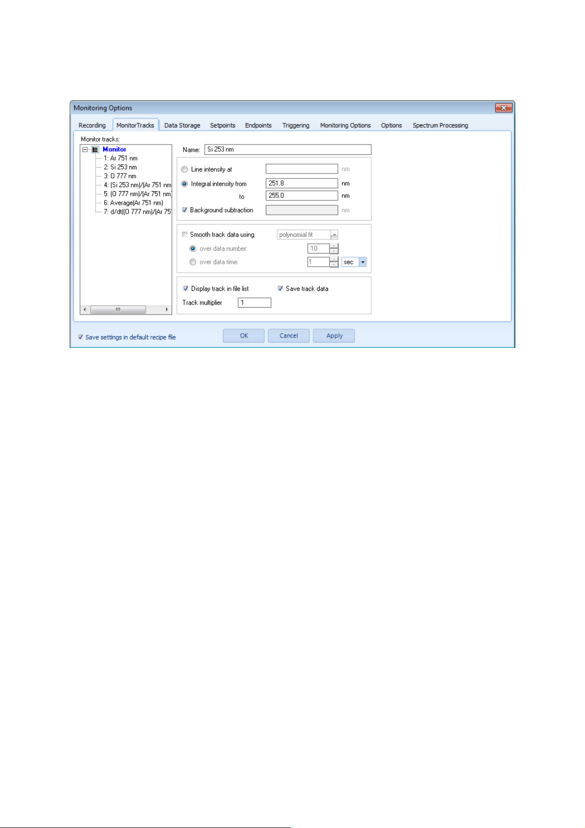
Monitor Tracks
(Single tracks)
Monitor tracks:
Name:
Line intensity at:
Integral intensity from … to:
Background subtraction:
Smooth track data using:
over data number:
over data time:
Display track in file list:
Save track data:
Track multiplier:
Selection list of monitor tracks
Displayed label of monitor track
Evaluate line intensity at given wavelength value
Evaluate intensity of line integral between given wavelength
values
Subtract background using:
- intensity value at given wavelength for line intensity
- calculated background intensity value between integral limits
The monitor track data is continuously smoothed using the
selected technique (polynomial fit or averaging)
Smoothing the monitor track data is carried out over the last
specified number of data points
Smoothing the monitor track data is carried out over the last
specified time period of data points
The track label is displayed in the file list window
The data values of the selected track are saved in the monitor
(.ecf) file if data saving is activated.
The actual value of monitor track is multiplied with this number for
further processing
Users‘ Manual - 35 - PLASUS EMICON MC
Page 36
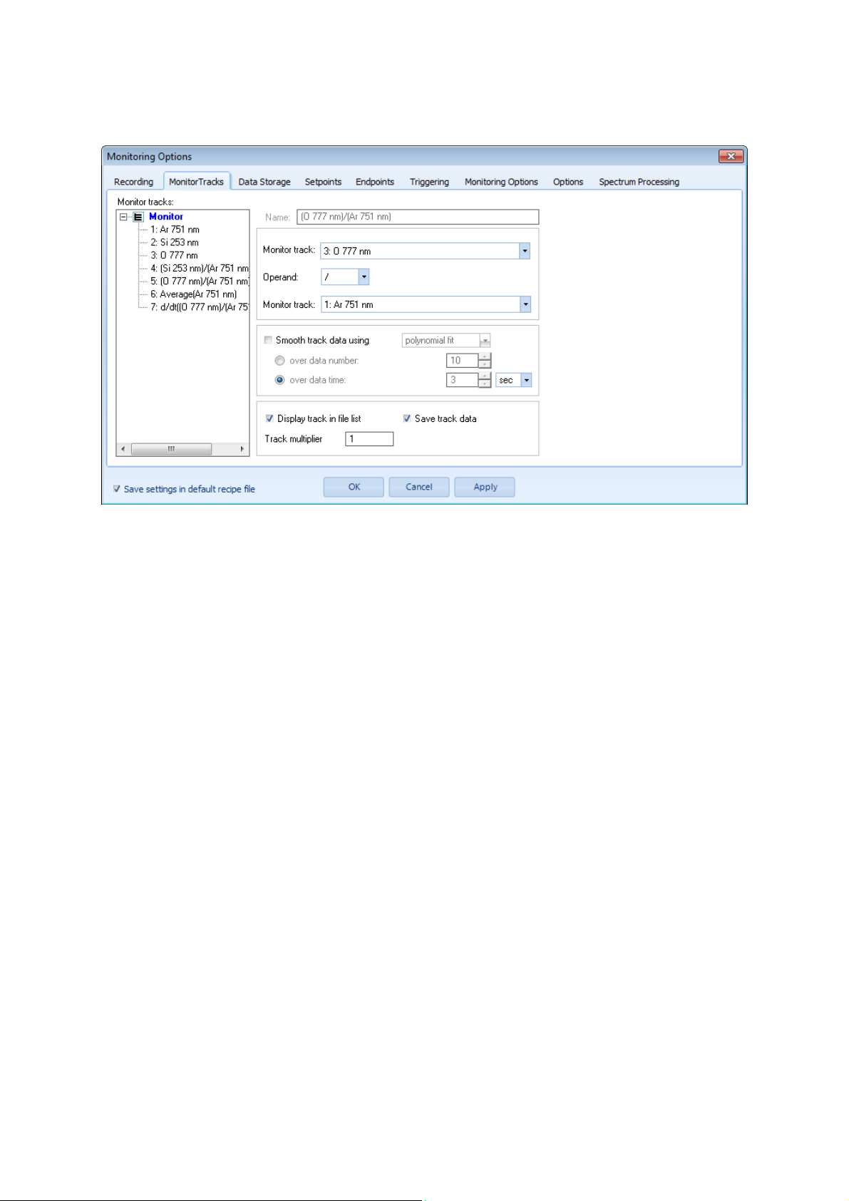
Monitor Tracks
(Combined tracks)
Monitor tracks:
Name:
Monitor track:
Operation:
Monitor track:
Smooth track data using:
over data number:
over data time:
Display track in file list:
Save track data:
Track multiplier:
Selection list of monitor tracks
Displayed label of monitor track
Selection list of first monitor track to be combined
Selection list of basic arithmetical operations for combining
monitor tracks
Selection list of second monitor track to be combined
The monitor track data is continuously smoothed using the
selected technique (polynomial fit or averaging)
Smoothing the monitor track data is carried out over the last
specified number of data points
Smoothing the monitor track data is carried out over the last
specified time period of data points
The track label is displayed in the file list window
The data values of the selected track are saved in the monitor
(.ecf) file if data saving is activated.
The actual value of monitor track is multiplied with this number for
further processing
Users‘ Manual - 36 - PLASUS EMICON MC
Page 37
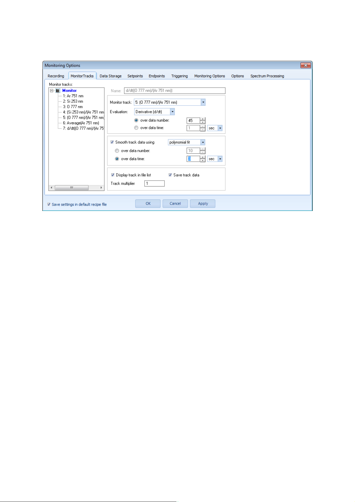
Monitor Tracks
(Evaluation tracks)
Monitor tracks:
Name:
Monitor track:
Evaluation:
over data number:
over data time:
Smooth track data using:
over data number:
over data time:
Display track in file list:
Save track data:
Track multiplier:
Selection list of monitor tracks
Displayed label of monitor track
Selection list of monitor tracks to be evaluated
Selection list of evaluations methods of specified monitor tracks
Evaluating the monitor track data is carried out over the last
specified number of data points
Evaluating the monitor track data is carried out over the last
specified time period of data points
The monitor track data is continuously smoothed using the
selected technique (polynomial fit or averaging)
Smoothing the monitor track data is carried out over the last
specified number of data points
Smoothing the monitor track data is carried out over the last
specified time period of data points
The track label is displayed in the file list window
The data values of the selected track are saved in the monitor
(.ecf) file if data saving is activated.
The actual value of monitor track is multiplied with this number for
further processing
Users‘ Manual - 37 - PLASUS EMICON MC
Page 38
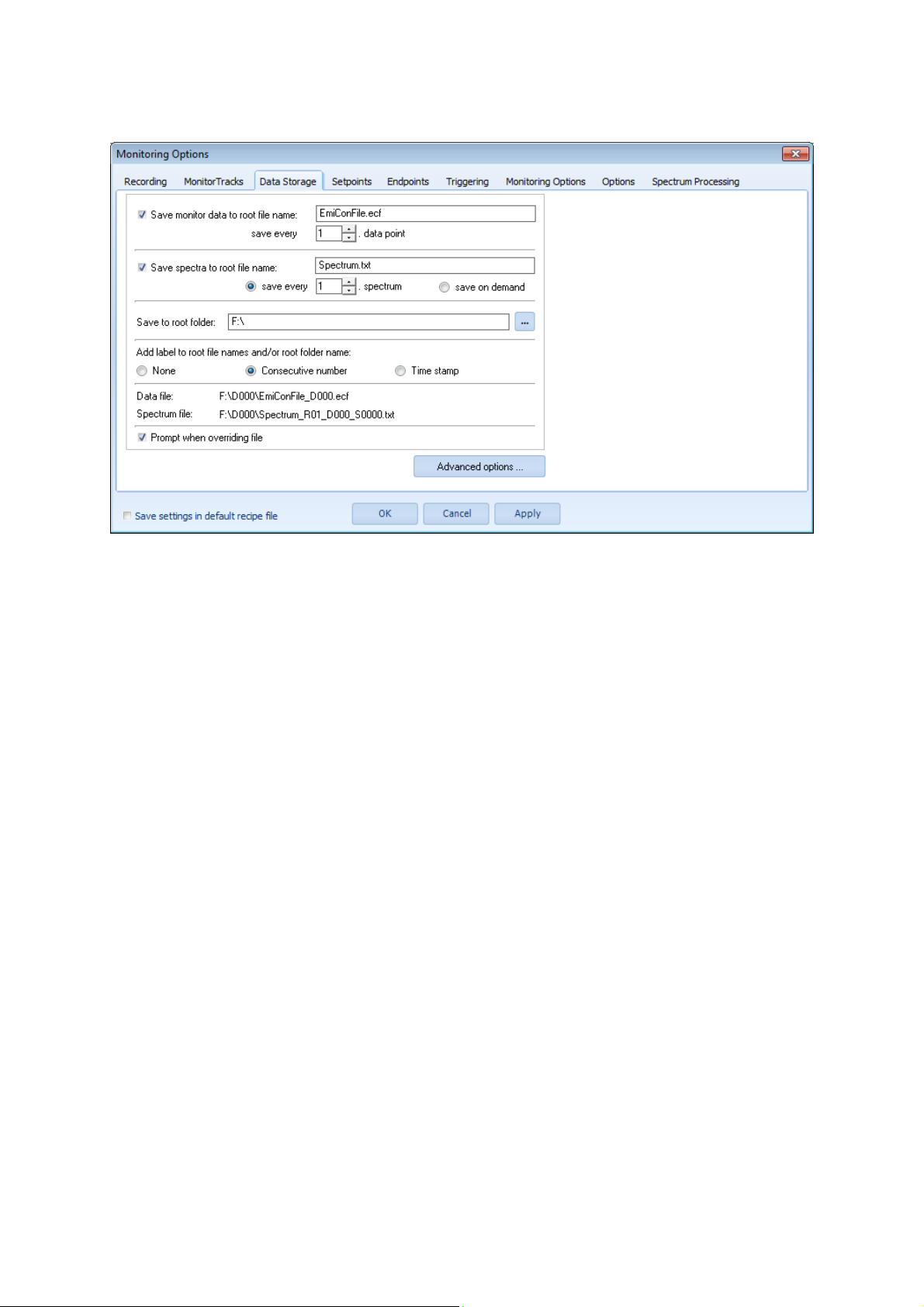
Data Storage
Save monitor data to root file name:
save every x. data point:
Save spectra to root file name:
save every x. spectrum:
save on demand:
Save to root folder:
Add label to root file names and/or folder
name: …
None / Consecutive Numbers / Time stamp
Data file:
Spectrum file:
Prompt when overriding file
For data saving the following delimiters are used for numbering:
_S... : spectrum counter
_D... : data file counter
_T... : time stamp
_R... : spectrum channel counter
_M... : monitor channel counter
_RD…: replay data counter
These delimiters may not be used elsewhere in the file name.
Save monitor data to root file name (.ecf) on hard disk. The root
file name will be automatically expanded by the monitor number
and data number/time stamp.
Only every specified data point is saved.
Save spectra to root file name (.txt) on hard disk. The root file
name will be automatically expanded by the record number, data
number/time stamp and spectrum number.
Only every specified spectrum is saved.
Save spectrum on demand.
Save monitor and spectra to specified root folder.
The root file names for the monitor data and/or spectra are
expanded with the specified notation for consecutive data series:
None, numbers or time stamp.
Compete file and folder name of monitor data file (.ecf)
Compete file and folder name of first spectrum file (.txt or .ecs) of
data series
Prompt when overriding files at the beginning of each recording
sequence.
Users‘ Manual - 38 - PLASUS EMICON MC
Page 39
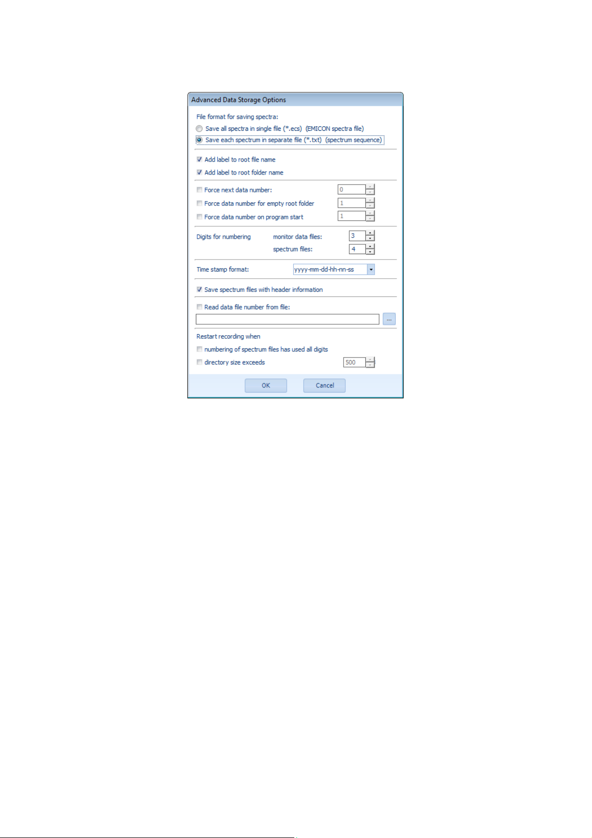
Advanced Data Storage Options
File format for saving spectra:
Add label to root file name:
Add label to root folder name:
Force next data number:
Force data number for empty folder:
Force data number on program start:
Digits for numbering
monitor data files:
spectrum files:
Time stamp format:
Save spectrum files with header
information
Read data file number from file:
Restart recording when
numbering of spectrum has used all digits
directory size exceeds … MB
Selection of available spectrum file formats:
- EMICON spectrum file format
- ASCII text file format
The notation for data series (_D...: numbers or T…: time stamp)
is added to the file names
The notation for data series (_D...: numbers or T…: time stamp)
is added to the folder name
The next data number will be the specified number. Otherwise the
next unused data number is used for saving the monitor data.
In a new root folder the specified number is first data number for
saving data.
On program start the specified number is the data number for
saving data.
Number of digits used for counting monitor data notation
Number of digits used for counting monitor notation
Select the time stamp format from the drop down list
Include recording options in the header of each spectrum file
The number for the next consecutively saved data file is read from
the specified file
When all digits of the spectrum numbering are used, i.e. the
spectrum number is e.g. 99999, the recording will restarted, a new
data directory is created and the spectra are saved in the new
directory starting with spectrum number 0.
When the directory size of exceeds the specified memory space
the recording will restarted, a new data directory will be created
and the spectra will be saved in the new directory starting with
spectrum number 0. Allowed range: 100 MB – 2 GB.
Users‘ Manual - 39 - PLASUS EMICON MC
Page 40
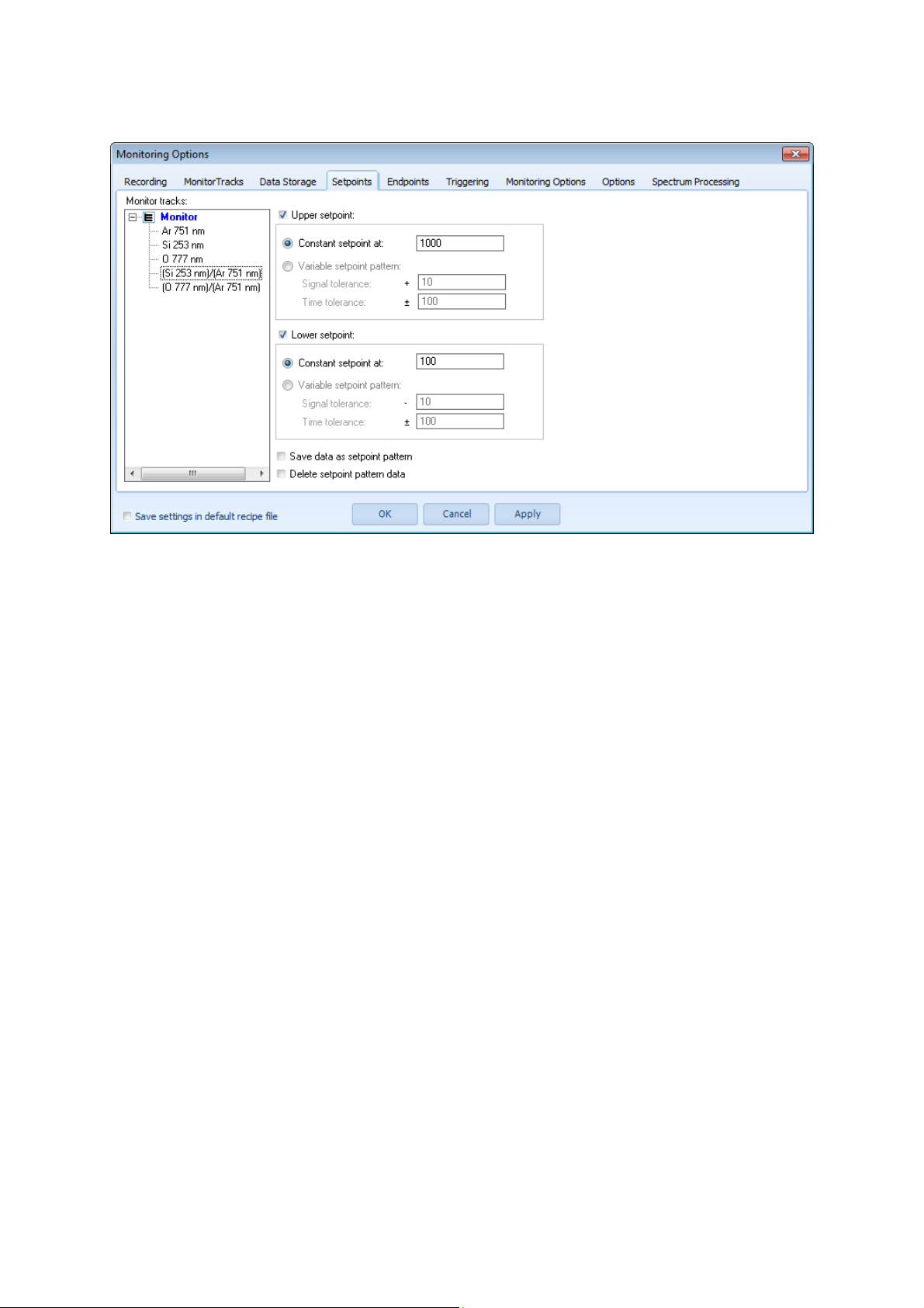
Setpoints
Monitor tracks:
Upper setpoint:
Constant setpoint:
Variable setpoint pattern:
Signal tolerance:
Time tolerance:
Upper setpoint:
Constant setpoint:
Variable setpoint pattern:
Signal tolerance:
Time tolerance:
Save data as setpoint pattern:
Delete set point pattern data:
Note:
Defining setpoints is the basis for using and applying any endpoints. Setpoints can be defined for each monitor
track and can be combined logically to endpoints.
Selection list of monitor tracks
Activate/deactivate upper setpoint for selected monitor track
Use constant setpoint at specified signal value (cts). Signal value
can be changed during recoding.
Use variable setpoint pattern with given tolerance values. The
setpoint pattern must be recorded and saved before (see below.
Signal tolerance (+ and -) in cts with respect to recorded setpoint
pattern.
Time tolerance (+ and -) in milleseconds with respect to recorded
setpoint pattern.
Activate/deactivate upper setpoint for selected monitor track
Use constant setpoint at specified signal value (cts). Signal value
can be changed during recoding.
Use variable setpoint pattern with given tolerance values. The
setpoint pattern must be recorded and saved before (see below.
Signal tolerance (+ and -) in cts with respect to recorded setpoint
pattern.
Time tolerance (+ and -) in milleseconds with respect to recorded
setpoint pattern.
When checked the recorded data is saved as setpoint pattern.
Removes the setpoint pattern from the current data
Users‘ Manual - 40 - PLASUS EMICON MC
Page 41
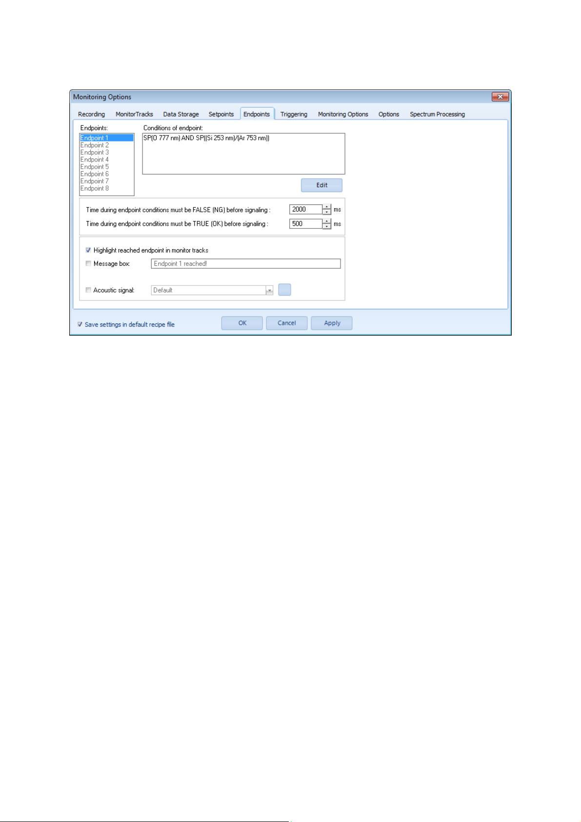
Endpoints
Endpoints:
Condition of endpoint:
Edit:
Time during endpoint conditions must be
FALSE (NG) before signaling:
Time during endpoint conditions must be
TRUE (OK) before signaling:
Highlight reached endpoint in monitor
tracks:
Message box:
Acoustic signal:
Note:
Endpoints are used to signaling that the specified setpoint combination is TRUE or FLASE. These endpoints can
be used further to provide a digital output signal (see Control Options).
Selection list of endpoints
Displays the condition of the selected endpoint: SP(…) stands for
setpoint condition of specified monitor track.
Open the dialog for editing the endpoint condition
The endpoint signal is given after the endpoint conditions has
been “FALSE” for the specified time without interruption, i.e.
during the given time period the endpoints condition must always
be FALSE.
The endpoint signal is given after the endpoint conditions has
been “TRUE” for the specified time without interruption, i.e. during
the given time period the endpoints condition must always be
TRUE.
A symbol with the number of the endpoint is shown on the monitor
window diagram at the specified track when the endpoint is
reached
Show the specified text in a message box on the screen when the
endpoint is reached
Play the specified acoustic signal when the endpoint is reached
Users‘ Manual - 41 - PLASUS EMICON MC
Page 42
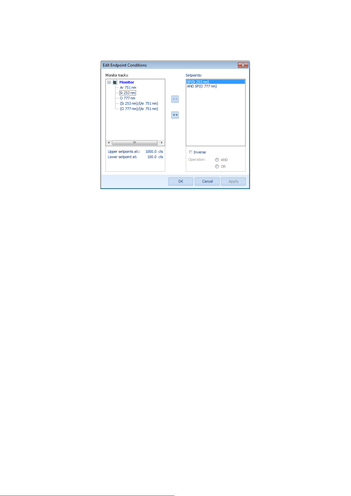
Edit Endpoint Conditions
Monitor tracks:
Setpoints:
Upper setpoint:
Lower setpoint:
Inverse:
Operand
Selection list of monitor tracks
List of setpoints added to the endpoint
Lower setpoint value of selected monitor track
Upper setpoint value of selected monitor track
The selected setpoint is evaluated inverted.
Boolean operation for endpoint condition between selected
setpoints.
Users‘ Manual - 42 - PLASUS EMICON MC
Page 43
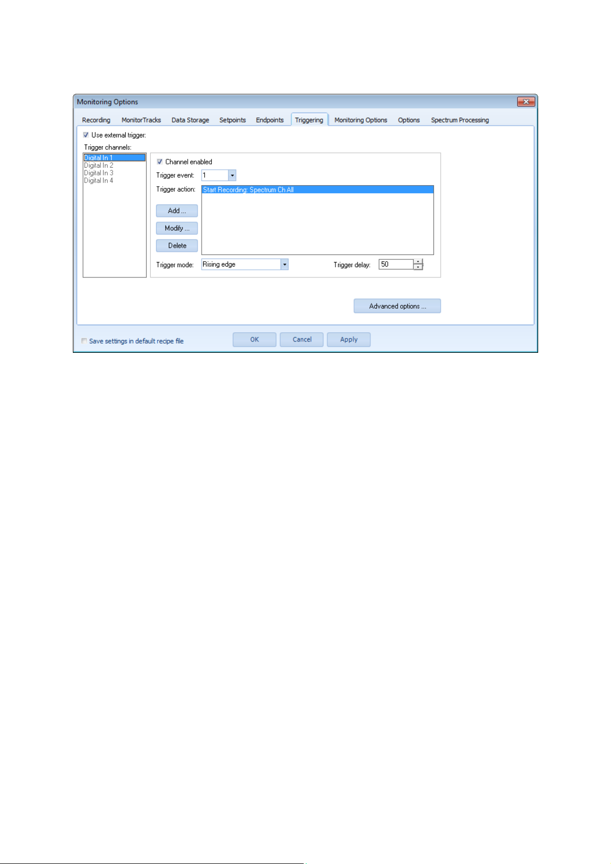
Triggering
Use external trigger:
Trigger channels:
Channel enabled:
Trigger event:
Trigger action:
Trigger mode:
Trigger delay:
Switch on/off external triggering
Selection list of trigger channels
Enable/disable selected trigger channel
Selection list of trigger events.
All trigger actions specified for the trigger event will be executed
at the incidence of this trigger event.
List if trigger actions for selected trigger event.
Add trigger action or /Modify/ Delete selected trigger action
Specify mode of triggering
Specify delay time for starting trigger action after trigger event
occurred
Users‘ Manual - 43 - PLASUS EMICON MC
Page 44
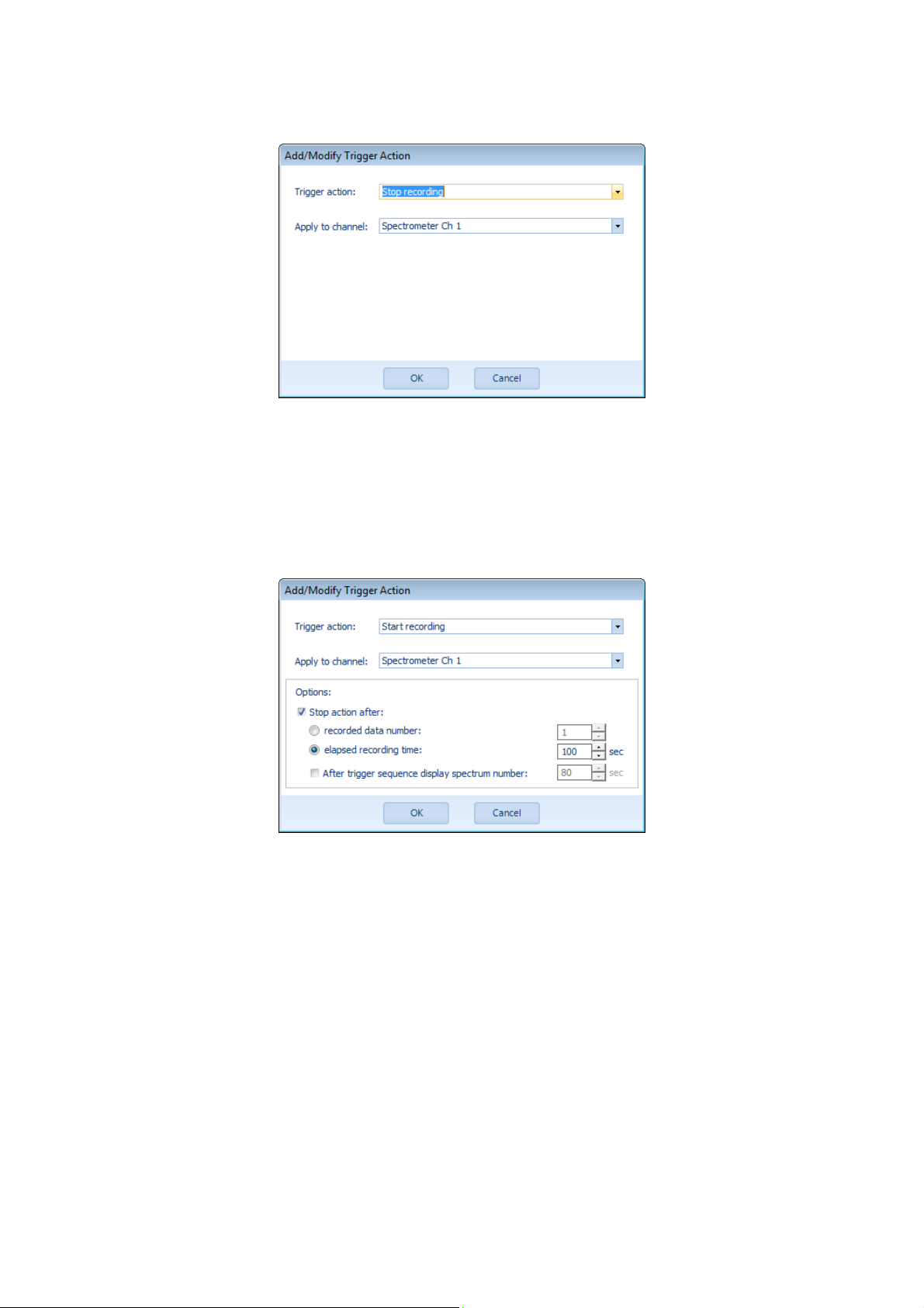
Add/Modify Trigger Action
Trigger action:
Add/Modify Trigger Action
(Start Recording/Controlling)
Trigger action:
Apply to channel:
Stop action after:
recorded data number:
elapsed recording time:
After trigger sequence display spectrum
number:
Selection list of trigger actions
Selection list of trigger actions
Selection list of spectrometer channels
Activate/deactivate trigger action stop after recorded data number
or elapsed recording time
The trigger action will be stopped after the specified number of
data has been recorded.
The trigger action will be stopped after the specified time period
has been elapsed.
When the trigger is stopped the specified spectrum number of the
trigger sequence will be displayed.
Users‘ Manual - 44 - PLASUS EMICON MC
Page 45
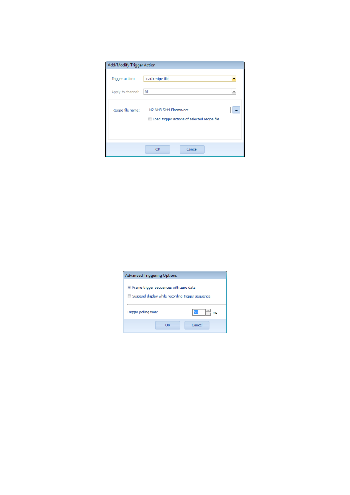
Add/Modify Trigger Action
(Load recipe file)
Trigger action:
Apply to channel:
Recipe file name:
Load trigger actions of selected recipe file:
Advanced Triggering Options
Selection list of trigger actions
All
Specify file name and folder of recipe to be loaded
Activate/deactivate the loading of the trigger actions from the
selected recipe file.
Please note: If this option is activated all trigger actions are
overridden by the trigger actions of the new file!
Frame trigger sequences with dark
spectra:
Suspend display while recording:
Trigger polling time:
Users‘ Manual - 45 - PLASUS EMICON MC
Each trigger sequence is displayed and stored with zero data at
the beginning and end of the sequence
While recording the display is suspended. The data is displayed
after each trigger sequence.
Polling time for checking the status of the digital input channels.
Page 46
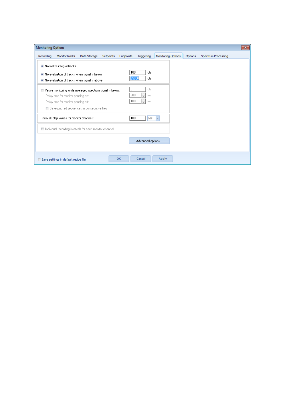
Monitoring Options
Normalize integral tracks:
No evaluation of tracks when signal is
below … cts
No evaluation of tracks when signal is
above … cts
Pause monitoring while averaged spectrum
signal is below ... cts:
Delay time for monitor pausing on:
Delay time for monitor pausing off:
Save sequences in consecutive files
Initial display values for monitor channels:
Individual recording interval for each
monitor channel:
All monitor tracks defined as integral intensity are scaled with the
integral width. This options allows an easy comparison with
monitor tracks defined as line intensity
Monitor tracks which actual signal is below the specified intensity
is not further evaluated. The intensity value from the previous data
point is taken instead.
Monitor tracks which actual signal is above the specified intensity
is not further evaluated. The intensity value from the previous data
point is taken instead.
Automatic pausing of evaluating monitor tracks when overall
intensity signal of spectrum channel is less than specified value
The monitor pausing is switched on after the overall intensity value
of the spectrum channel has been below the limit for the specified
delay time without interruption.
The monitor pausing is switched off after the overall intensity value
of the spectrum channel has been above the limit for the specified
delay time without interruption.
The recorded spectra and monitor data is stored in consecutive
files and folders for each pausing off – pausing on series.
Initial display interval of time and intensity for the monitor data in
the monitor window diagram.
Allow individual values for each spectrometer channel.
(Only available if more than one monitor channel is defined)
Users‘ Manual - 46 - PLASUS EMICON MC
Page 47

Advanced Monitoring Options
Display unit:
Storage interval(RAM):
Unit of time scale
Time interval for which recorded data is stored in RAM memory.
Please be aware of available memory!
Users‘ Manual - 47 - PLASUS EMICON MC
Page 48
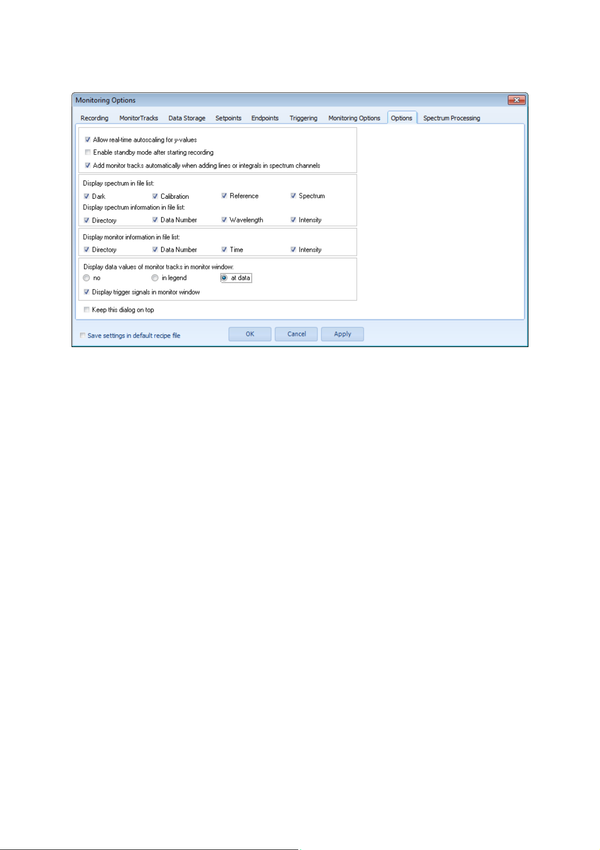
Options
Allow real-time autoscaling for y-values:
Enable standby after starting recording:
Add monitor tracks automatically when
adding lines or integrals in spectrum
channels:
Save sequences in consecutive files
Display spectrum in file list:
Display spectrum information in file list:
Display monitor information in file list
Display data values of monitor tracks in
monitor window:
Automatic autoscaling of the y-values while recording data. The
autoscaling can be switched on and off with the commands
Y-Autoscale and Y-Autoscale single track.
After pushing the button Start Recording the EMICON system
initializes the data recording and goes in standby mode. The
recording will start immediately after leaving the standby mode.
With each line or integral defined in the spectrum channels a
monitor track is added in the corresponding monitor channel. If
switched off a monitor track must be added manually by the user.
The recorded data is stored in consecutive files or consecutive
folders with ongoing numbers.
Specify which spectra of the spectrum channels are displayed in
the file list.
Specify which information about the spectra is displayed in the file
list.
Specify which information about the monitor data is displayed in
the file list.
Display current intensity value of monitor tracks at specified
location in the monitor window.
Users‘ Manual - 48 - PLASUS EMICON MC
Page 49
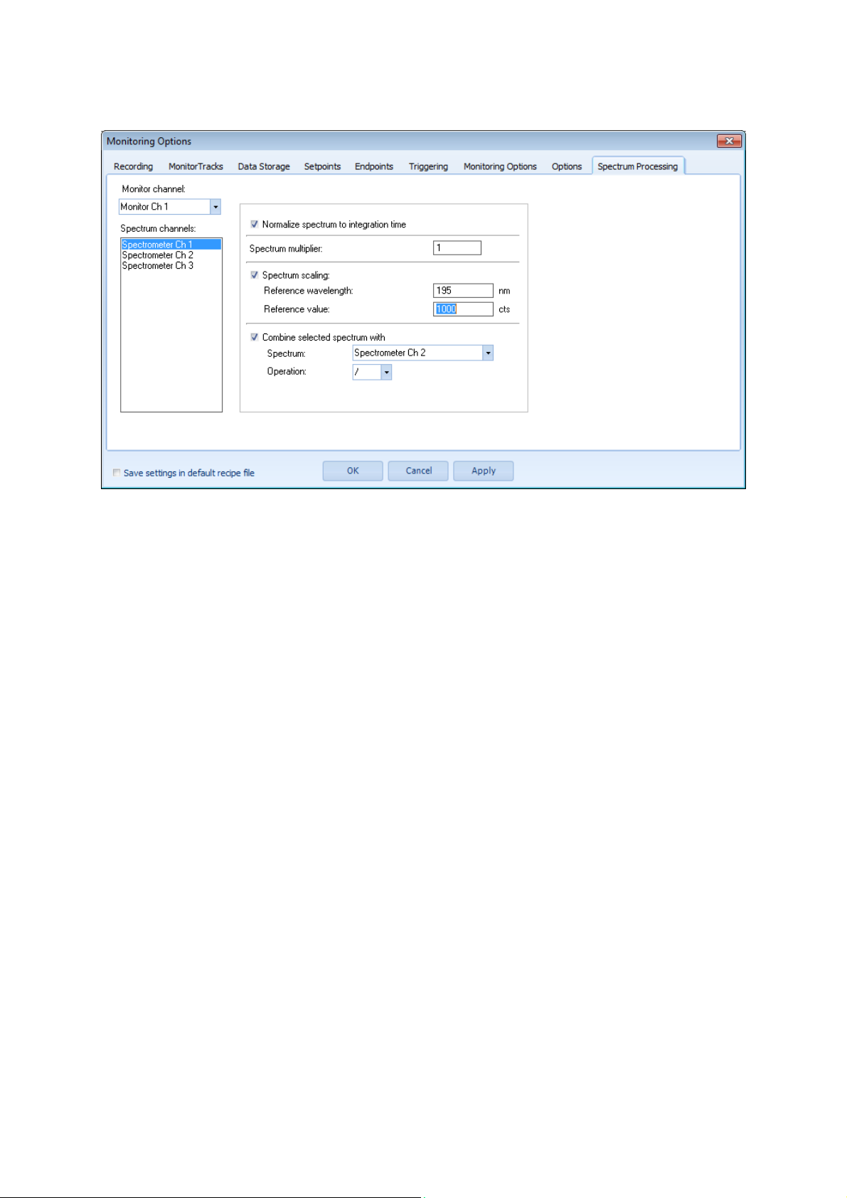
Spectrum Processing
Monitor channel:
Spectrum channels:
Spectrum multiplier:
Spectrum scaling:
Reference wavelength:
Reference value:
Combine selected spectrum with:
Spectrum:
Operation:
All settings apply to the selected monitor channel
Selection list of spectrum channels
All intensity values of the actual spectrum are multiplied with this
number for further processing
The intensity values of the spectrum are scaled to the specified
intensity value.
The spectrum is scaled to the intensity value at the specified
wavelength
The intensity value at reference wavelength
Combining the intensity values of selected spectra for each
wavelength value
Selected spectrum which is combined with the spectrum selected
in the spectrum channel list
Selection list of basic arithmetical operations for combining the
intensity values of each wavelength value
Users‘ Manual - 49 - PLASUS EMICON MC
Page 50
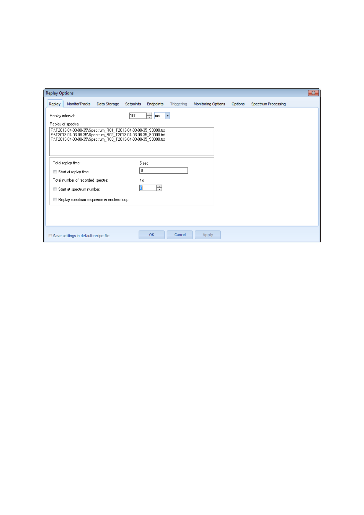
Replay Options
(Only available in “Replay Mode”)
Dialog for setting and changing replay options with the following tab sheets:
Replay
Replay interval:
Replay of spectra:
Total replay time:
Start at replay time:
Total number of recorded spectra:
Start at spectrum number:
Replay spectrum sequence in endless loop
Display recording time from spectrum files
All other tab sheets of the Replay Options dialog are the same as the tab sheets of the Monitoring Opti ons dialog;
however, some features are not available like Triggering and saving of spectrum files.
General:
Default values
Replay interval between consecutive spectrum files
With the replay interval the replay speed is speeded up or slowed
down.
List of spectrum files which are replayed
Total replay time saved on hard disk
The replay is started at the specified replay time
Total number spectrum files per channel saved on hard disk
The replay is started at the specified spectrum file number
After reaching the end of the spectrum file sequence the replay
starts again from the beginning automatically.
When replaying the time from the recording is displayed not the
actual time.
The current recipe settings are saved in the default recipe
Users‘ Manual - 50 - PLASUS EMICON MC
Page 51
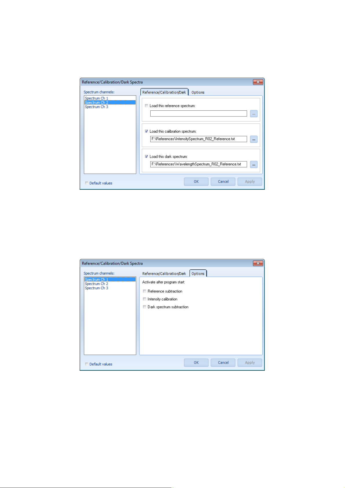
Reference/Calibration/Dark Spectra
Dialog for setting and changing the default options for background, calibration and reference files:
Reference/Calibration/Background
Record Channels:
Load this reference spectrum:
Load this calibration spectrum:
Load this background spectrum:
Options
Selection list of record channels
The specified reference spectrum will be loaded on start-up.
The specified calibration spectrum will be loaded on start-up.
The specified background spectrum will be loaded on start-up.
Record Channels:
Load this reference spectrum:
Load this calibration spectrum:
Load this background spectrum:
Users‘ Manual - 51 - PLASUS EMICON MC
Selection list of record channels
The specified reference spectrum will be loaded on start-up.
The specified calibration spectrum will be loaded on start-up.
The specified background spectrum will be loaded on start-up.
Page 52

Users‘ Manual - 52 - PLASUS EMICON MC
Page 53
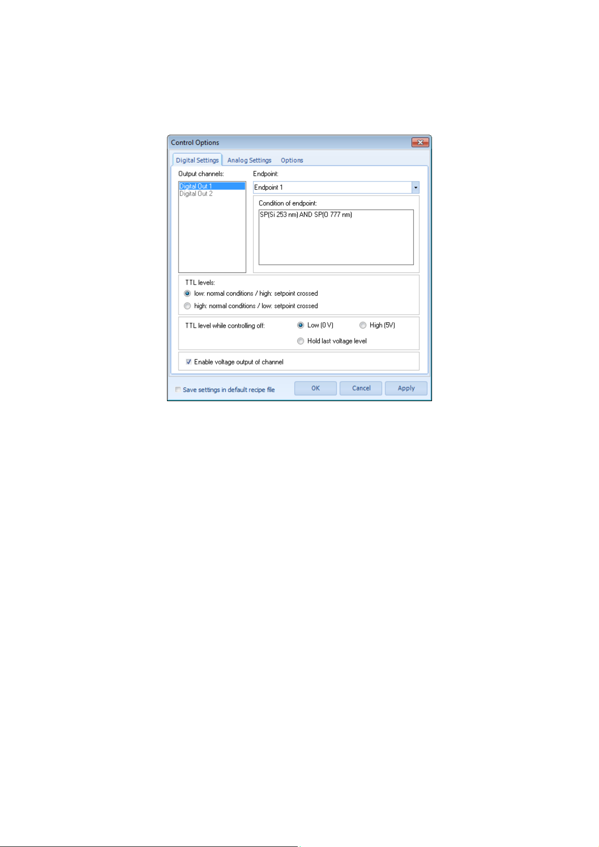
Control Options
Dialog for setting and changing controlling options with the following tab sheets:
Digital Settings
Output channels:
Endpoint:
Condition of endpoint:
TTL levels:
low: normal conditions /
high: setpoint crossed:
high: normal conditions /
low: setpoint crossed.
TTL level while controlling off:
Enable voltage output of channel
General:
Default values
Selection list of available digital output channels
Selection list of endpoints to be assigned to selected output
channel.
Displays the condition of the selected endpoint. For editing the
endpoint condition go to the tab sheet Endpoints of the Monitoring
Options dialog.
normal TTL signaling
inverse TTL signaling
Specify the TTL level for switched off controlling (idle state)
Switch on/off voltage output for selected output channel
The current recipe settings are saved in the default recipe
Users‘ Manual - 53 - PLASUS EMICON MC
Page 54
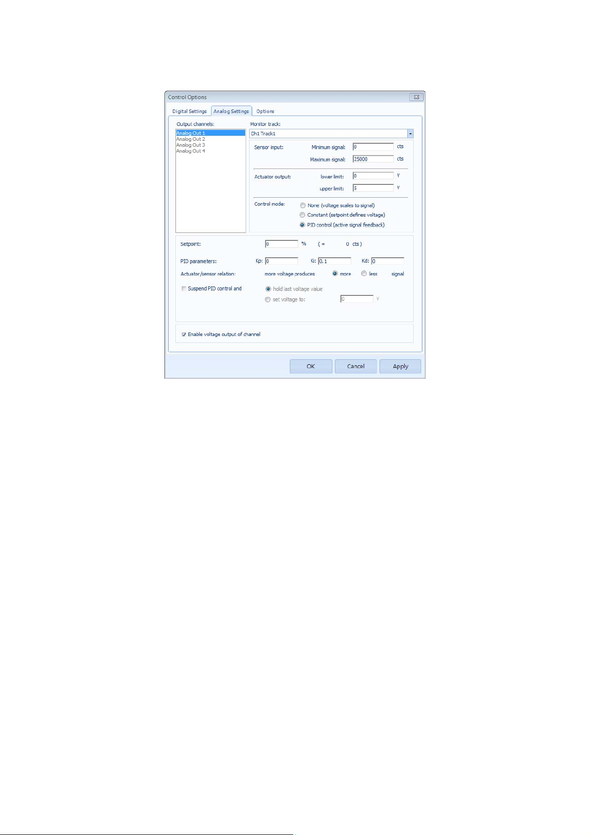
Analog Settings
Output channels:
Monitor track:
Sensor input:
Actuator output:
Control mode:
None (voltage scales to signal)
Constant (setpoint defines voltage)
PID control (active feedback control)
Setpoint:
PID parameters:
K
p
K
i
K
d
Actuator/sensor relation:
Suspend PID control:
Enable voltage output: of channel
Selection list of available analog output channels
Selection list of monitor tracks to be assigned to selected output
channel
Minimum and maximum signal value of selected monitor tracks for
lowest and highest actuator output
Minimum and maximum actuator output
Minimum and maximum actuator output
Voltage output is determined by linear scaling of sensor input and
actuator output numbers
Constant voltage output determined by linear scaling of sensor
input and actuator output numbers
Active feedback control according scaling of sensor input and
actuator output numbers and give PID parameters
Setpoint value in percent of selected monitor track
Proportional parameter of PID control
integral parameter of PID control
derivative parameter of PID control
Direct/inverse mode of PID control
Suspend PID control and keep given voltage output.
Switch on/off voltage output for selected output channel
Users‘ Manual - 54 - PLASUS EMICON MC
Page 55
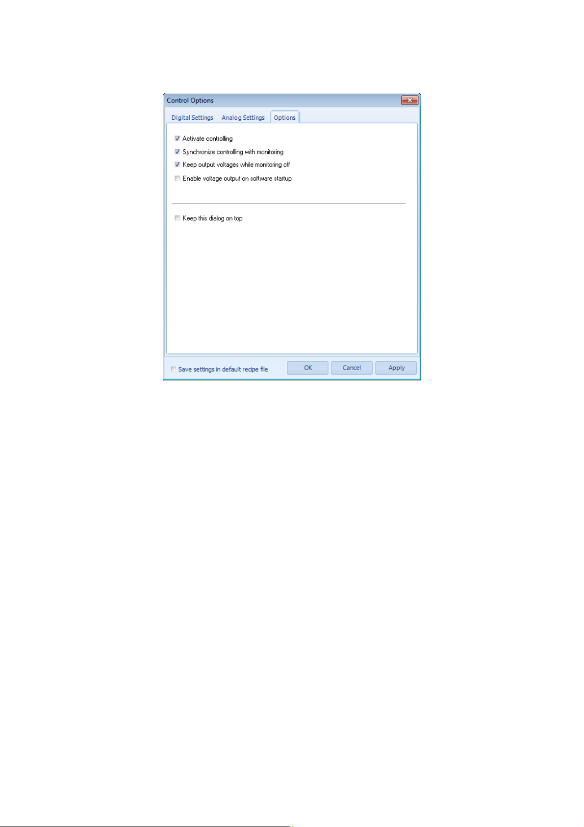
Options
Activate controlling:
Synchronize controlling with monitoring:
Keep output voltages while monitoring off:
Enable voltage output on software startup:
Keep this dialog on top:
Switch on/off general controlling feature
Controlling is activated and deactivated together with the
commands Start Monitoring and Stop Monitoring, respectively.
The voltage of the analog outputs and the TTL levels of the digital
outputs are hold even when the monitoring is stopped.
On program start the voltage output will be activated. Thus, in
combination with above option the “voltage off” signals are
provided automatically on software startup.
The Control Options Dialog is always in the foreground.
Users‘ Manual - 55 - PLASUS EMICON MC
Page 56
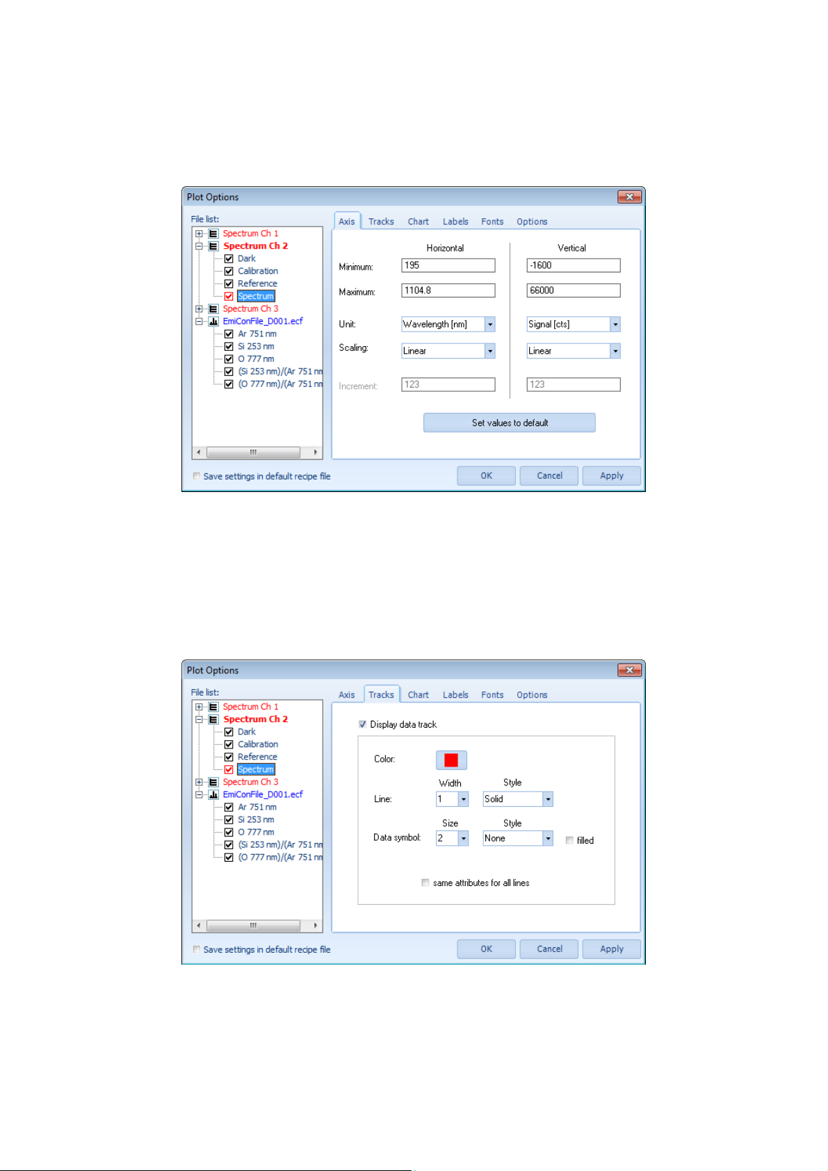
Plot Options
Dialog for setting and changing plot options with the following tab sheets:
Axis
Minimum
Maximum:
Unit:
Scaling:
Increment:
Tracks
Lower display value
Upper display value
Unit of axis
Scaling method of display
Reserved
Display track:
Line:
same attributes for all lines: Line options are applied to all tracks
General:
File list:
Users‘ Manual - 56 - PLASUS EMICON MC
Display track in diagram
Line options of selected track: color, width and style
Selection list of files and tracks
Page 57
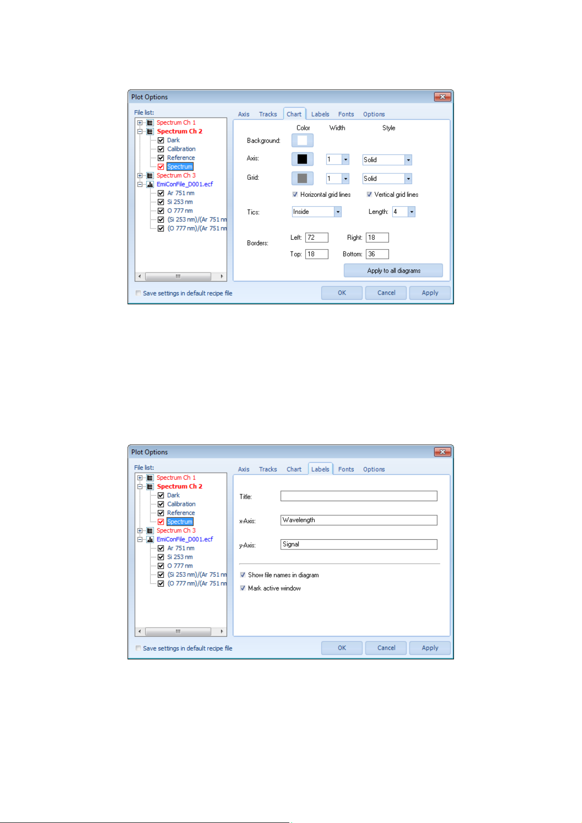
Chart
Background:
Axis:
Grid:
Horizontal grid lines:
Vertical grid lines:
Tics:
Borders:
Labels
Background color
Line options of axis: color, width and style
Line options of grid: color, width and style
Display horizontal grid lines
Display vertical grid lines
Position and Length of unit tics
Border width of diagram
Title:
x-Axis:
y-Axis:
Show file name in diagram
Mark active window
Users‘ Manual - 57 - PLASUS EMICON MC
Title of diagram
Label of x-axis
Label of y-axis
The current spectrum and monitor file name is displayed in lower
left corner of each spectrum and monitor window.
The currently selected and active window is marked with a red
border.
Page 58
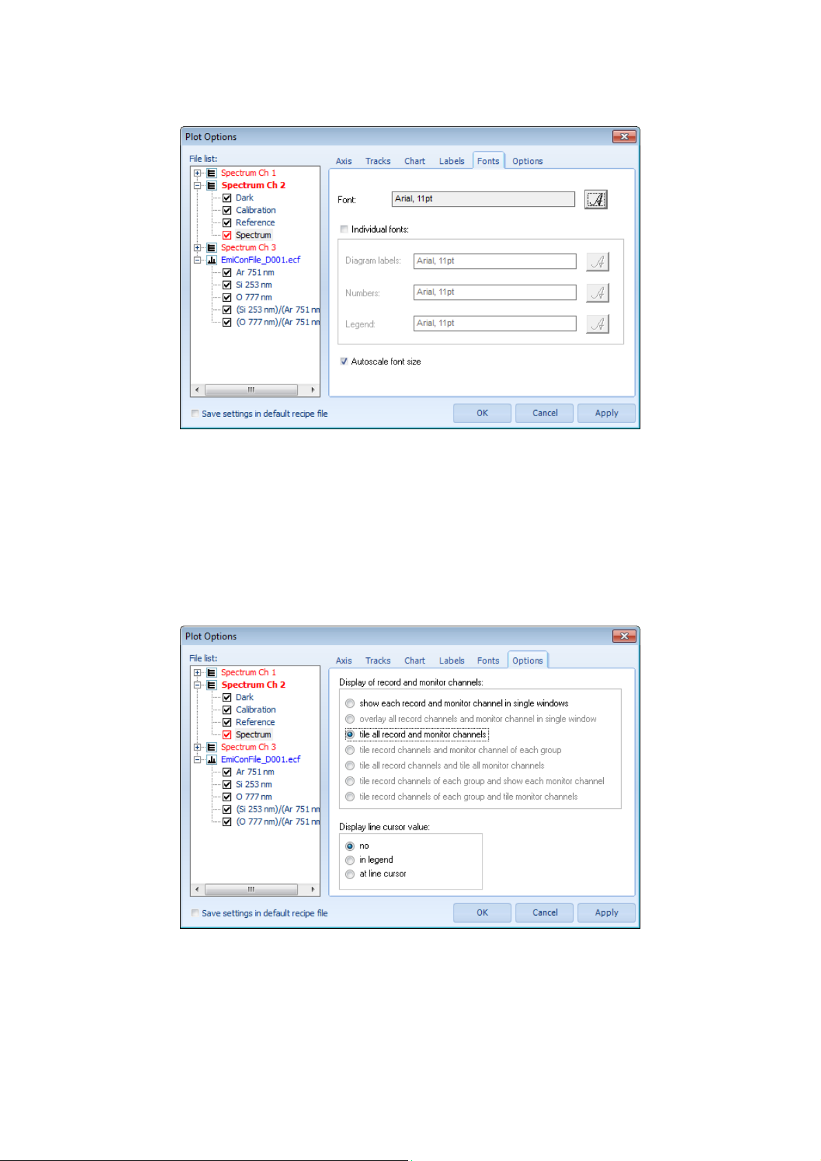
Fonts
Font:
Individual fonts:
Diagram labels:
Numbers: Font of numbers
Legend:
Autoscale font size:
Options
General font
Individual fonts
Font of diagram labels
Font of legend
The fonts size is scaled automatically from the number of
displayed windows.
Display of record and monitor channels:
Display line cursor value:
no:
in legend:
at line cursor:
Users‘ Manual - 58 - PLASUS EMICON MC
The record and monitor channel are displayed as specified. Some
options are available for multi-channel systems only.
no display
value is displayed in legend
value is displayed at line cursor
Page 59
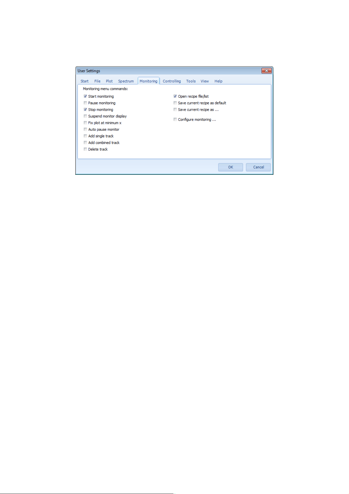
Using Settings
Dialog for the configuration of the user mode setting.
The selected commands are enabled in user mode, all others are disabled.
Notice:
Changing between administrator and user mode requires a password. The default password is admin.
If you don‘t remember your password copy the default administration file “admin“ from the installation CD in the
program folder.
Users‘ Manual - 59 - PLASUS EMICON MC
Page 60
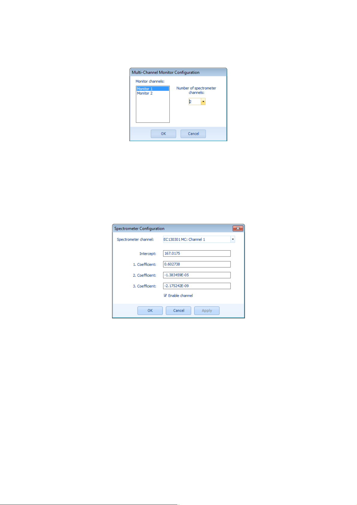
Multi-channel Configuration
Dialog for configuring the multi-channel monitor set-up:
Monitor channels:
Number of record channels:
List of monitor channels for the current configuration.
Please select from the drop down list the number of record
channels which should be assigned to the selected monitor
channel.
Spectrometer Configuration
Dialog for changing the spectrometer configuration:
Warning: These settings should only be changed by experienced users!
Spectrometer channel:
Intercept:
First coefficient:
Second coefficient:
Third coefficient:
Enable channel:
Users‘ Manual - 60 - PLASUS EMICON MC
Serial number and channel number of the EMICON system
Intercept wavelength of regression fit
First coefficient of regression fit
Second coefficient of regression fit
Third coefficient of regression fit
Activate/deactivate the selected spectrometer channel
Page 61
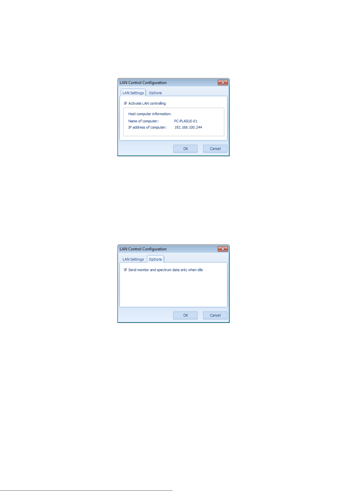
LAN Control Configuration
Dialog for configuring the optional LAN control function:
LAN Settings
Activate LAN controlling:
Host computer information:
Name of computer:
IP address of computer: Unique IP address of this host computer
Note: For detailed information on LAN controlling, refer to the LAN control manual.
Options
Send monitor and spectrum data only
when idle:
Switch on/off LAN controlling
Information about this host computer necessary to connect from a
client computer.
Public name of this host computer.
Monitor data and spectrum data is transmitted via LAN only, when
the EMICON software is idle. i.e. the data processing is not
disturbed or delayed.
Users‘ Manual - 61 - PLASUS EMICON MC
Page 62
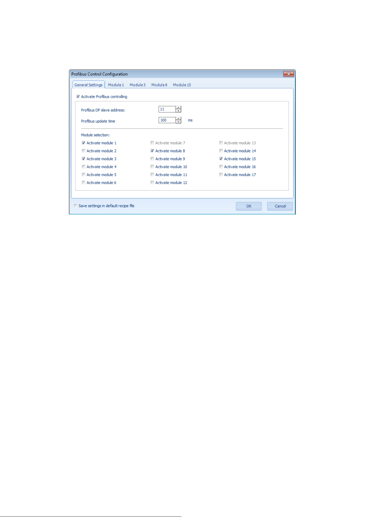
Profibus Control Configuration
Dialog for configuring the optional Profibus control function:
Activate Profibus controlling:
Profibus DP slave address:
Profibus update time:
Module selection: .Modules activated for Profibus transmission
Note: For detailed information on Profibus controlling refer to the Profibus control manual.
Switch on/off Profibus controlling
DP slave address in the connected Profibus net.
Update time for Profibus data.
Users‘ Manual - 62 - PLASUS EMICON MC
Page 63
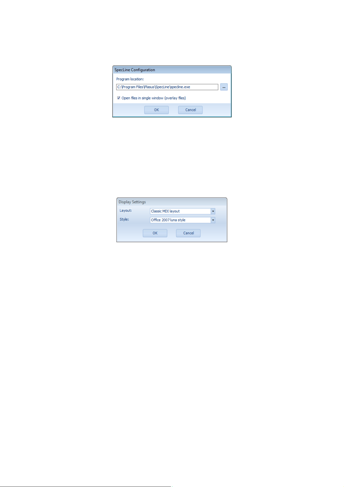
SpecLine Configuration
Dialog for configuring the optional tool Plasus SpecLine:
Program location:
Open files in single window:
Directory and file name of executable file of PLASUS SpecLine.
In SpecLine all spectra are opened in a single window (Overlay
mode) or in separate windows.
Display Settings
Dialog for configuring the layout of the EMICON program:
Layout:
Style:
Type of Windows
Windows
®
®
style of application .
application
Users‘ Manual - 63 - PLASUS EMICON MC
Page 64
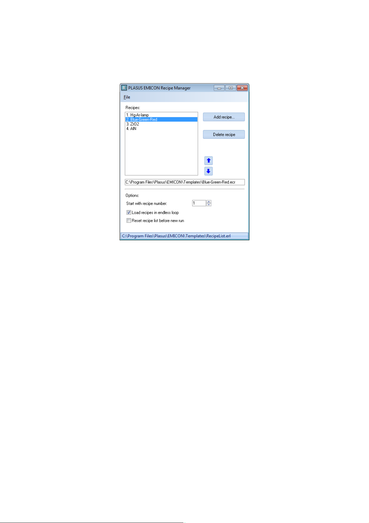
Recipe Manager
Dialog creating and editing recipe lists.
Please note: All recipe to be used for a recipe list must already exist!
File:
Recipes:
Add recipe …:
Delete recipe: Delete selected recipe form recipe list. The recipe itself is not
Up/Down arrows:
Recipe:
Options:
Initial recipe
Load recipe in endless loop:
Reset recipe list for next run:
Menu to create a new recipe list or open an existing recipe list
List of recipes in recipe list
Add an existing recipe to recipe list
deleted.
The selected recipe is moved upwards or downwards in the recipe
list.
Full folder and file name of selected recipe.
Specify the number of the recipe which should be loaded when
opening the recipe list.
When the last recipe in the recipe list is reached the next recipe
to be loaded is first one again.
The recipe list is initialized every time a new monitoring is started
Users‘ Manual - 64 - PLASUS EMICON MC
Page 65
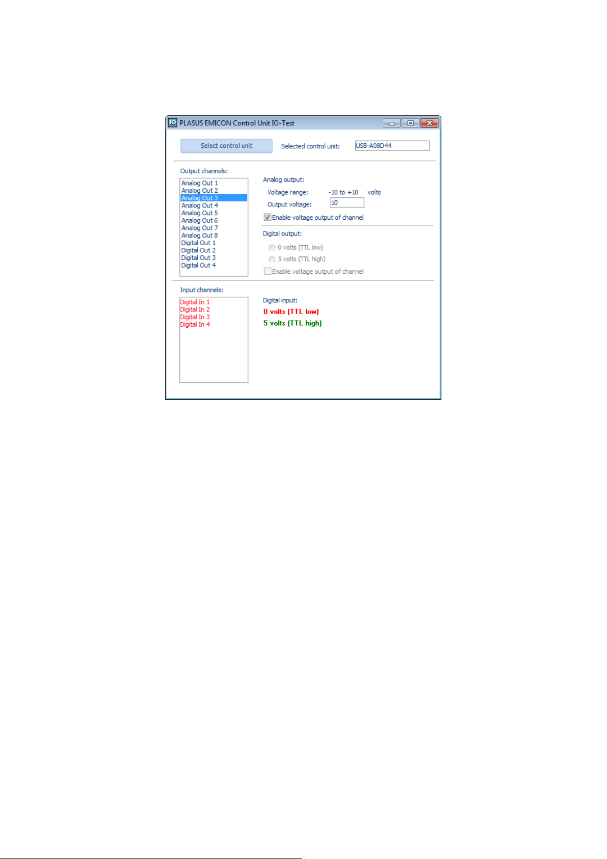
Control Unit IO-Test
Dialog for the checking and testing the inputs and outputs of the control unit.
Select control unit:
Selected control unit:
Output channels:
Analog output:
Voltage range:
Output voltage …. volts:
Enable voltage output of channel:
Digital output:
0 volts (TTL low):
5 volts (TTL high):
Enable voltage output of channel:
Input channels:
Digital input
0 volts (TTL low):
5 volts (TTL high):
Press to select control unit from selection list. Only connected
control units are displayed in the drop down list.
Currently selected and activated control unit
Selection list of all output channels of control unit
Maximum voltage range of analog output of selected control unit
Voltage to be applied to selected output channel
Enable/disable voltage output for selected output channel
Output voltage of selected output channel is 0 volts, i.e. TTL low
Output voltage of selected output channel is 5 volts, i.e. TTL high
Enable/disable voltage output for selected output channel
List of all input channels of control unit
If the applied input voltage is 0 volts (TTL low) the corresponding
input channel name is given in red in the input channel list.
If the applied input voltage is 5 volts (TTL high) the corresponding
input channel name is given in green in the input channel list.
Users‘ Manual - 65 - PLASUS EMICON MC
Page 66
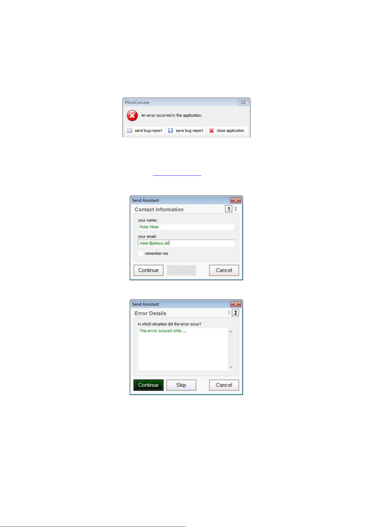
Bug Reports
The bug-reporting feature will us a direct feedback of runtime errors and exceptions. By sending the automatically
produced bug reports to our support team you will help us to remove program errors efficiently and improve the
software.
In case an error occurs, you will get the following message box:
If the computer has direct access to the internet, please press “Send bug report” and the bug report will be sent to
our support team via an included mail service.
If the computer has no internet connection, please press “Save bug report” and save the bug report to the hard
disk. Please e-mail the saved bug report to [email protected].
If you have chosen to send the bug report directly, please fill in the information of the following contact form:
Eventually, add some information about the occurred error in the error details form (optional):
By pressing the “Continue” button, the bug report will be send or saved depending on your previous selection.
We would very much appreciate if you will support us to improve our software by sending the bug reports to our
support team.
Thank You!
Users‘ Manual - 66 - PLASUS EMICON MC
Page 67

Users‘ Manual - 67 - PLASUS EMICON MC
Page 68

Company Information
Since 1996 PLASUS provides high-quality products for plasma spectroscopy and plasma monitoring and plasma
process controlling which are used in R&D applications as well as in production lines:
Our powerful spectroscopic software PLASUS SpecLine simplifies and extends the evaluation and analysis of
spectral data. It comes with an extensive and unique data base for atoms and molecules for the identification of
plasma species. The software can be added to all common spectroscopic data acquisition systems. Please feel
free to download a trial version of the line identification software PLASUS SpecLine from our web site.
Our optical plasma monitor and process control system PLASUS EMICON provide full online analysis and control
of plasma processes by observing different plasma species simultaneously.
In addition we offer our experience in consulting by supporting our customers in evaluating and interpreting their
individual spectroscopic data and by setting up spectroscopic systems.
Our products are sold worldwide.
PLASUS Hotline
If you have problems, questions or suggestions concerning PLASUS EMICON, don‘t hesitate to contact us:
Phone: +49 - 8233 - 73 53 78-0
E-Mail: [email protected]
PLASUS Address
PLASUS GmbH
Lechstrasse 9
D-86415 Mering
Germany
Tel.: +49 - 8233 - 73 53 78-0
Fax: +49 - 8233 - 73 53 78-9
E-Mail: [email protected]
Internet: www.plasus.de
Users‘ Manual - 68 - PLASUS EMICON MC
Page 69

Users‘ Manual - 69 - PLASUS EMICON MC
Page 70

Version History
(Releases only)
Date Version
2017-12-19 3.75.9.5
2017-09-11 3.75.9.3
2017-05-23 3.75.7.5
2017-03-15 3.75.7.3
2017-01-16 3.75.5.1
2016-12-14 3.75.3.3
2016-08-30 3.51.3.6
2015-12-22 3.51.3.6
2015-12-10 3.51.5.3
2015-08-24 3.51.2.31
2015-06-24 3.51.2.29
2015-05-17 3.51.2.27
2015-01-10 3.51.2.25
2014-09-02 3.51.2.23
2014-06-12 3.51.2.22
2014-05-29 3.51.2.21
Program
- PID control features improved
- Several bugs removed
Program
- Improved PID control algorithm implemented
- New GUI for PID settings implemented
- Control unit driver updated and driver registration improved
Program
- Transmission/reflection/absorbance feature improved
- Several bugs removed
Program
- Windows layout for High-DPI display adapted
Program
- New: Transmission, reflection and absorbance measurement
- Zooming, scrolling and auto-scaling improved
Program
- AutoPause function for multi-monitor-channel configurations implemented
- Driver updates for spectrometer modules and control unit solving several
issues for operation with Windows 8 and 10.
- Several bugs resolved.
Program
- Several bugs resolved.
LAN remote control interface
- New: Option for sending monitor and spectrum data immediately
Program
- Monitor track scaling: Offset added
- Memory leakage in long term operation removed
Profibus remote control interface
- New status bits added
Program
- Bug in saving monitor data fixed
Profibus remote control interface
- Validity checks of transfer data added
Program
- Multi-channel labeling updated.
- PID control response curve:
- voltage output corrected
- multi-channel properties updated
Program
- Bugs in legacy drivers fixed.
- Bugs in replay mode for legacy file formats fixed.
Program
- Bug in replay mode fixed.
- Bug in control mode and voltage output fixed.
Program
- Bug saving line options fixed.
LAN remote control interface
- New: Saving specific recipe data to text file
Program
- Error reporting function updated.
Profibus interface
- Bugs in interface functions removed.
Users‘ Manual - 70 - PLASUS EMICON MC
Page 71

2014-04-15 3.51.2.19
2014-03-28 3.51.2.17
2013-12-23 3.51.2.15
2013-12-09 3.51.2.13
2013-10-19 3.51.2.11
2013-10-07 3.51.2.10
2013-10-01 3.51.2.9
2013-08-26 3.51.2.6
2013-08-11 3.51.2.5
2013-05-12 3.51.0.16
2012-07-25 3.51.0.5
Program
- New: Control option “Enable voltage output on software startup” added
- Several bugs fixed in multi-channel monitor configuration:
- Selection of all monitor tracks for analog output is now possible
- Editing endpoints is now assigned to selected monitor channel
- Saving and loading of setpoint assignments to endpoints is now working
- Wrong display of file names under Asian Window OS corrected
Program
- Bugs in replay mode using time stamp removed.
Program
- New: Add evaluation monitor track of moving average, integral, derivative,
polynomial fit and standard deviation
- New: Smoothing monitor track data by polynomial fit or moving average
- Display delay times of voltage outputs in system status window.
- Trigger actions of new recipe is loaded when selected by recipe selection list
- Trigger actions of new recipe is optionally loaded when selected by trigger
action Load recipe file.
Bug in holding endpoint signal during delay time fixed
- Bug in auto pause functions fixed
- Initial state of toolbar buttons are shown correctly
Program
- Bugs in saving spectra and monitor data in trigger mode removed.
- Voltage output while monitoring off corrected
- Line cursor can be used while setpoints defined
Bug in sending error report via e-mail to PLASUS Support fixed
Program
- Bug in Control Options dialog fixed.
LAN remote control interface
- Bug while opening recipe file fixed
- Loading recipe file ignored if recipe is not located on EMICON computer
Program
- Menu bugs fixed.
- Output voltage of PID setpoint will not change if response curve scaling has
changed.
LAN remote control interface
Support of new messages for:
- assigning monitor tracks to analog output channels
- changing voltage and signal values for response curve scaling
Program
- New: error reporting functionality: Bug report automatically send by e-mail to
PLASUS support.
Program
Controlling:
- Output voltage OFF after launch of program (safety requirement)
- Voltage output will be ON either after switching on controlling or after
activating voltage output by menu command.
- New option: Keep output voltage while monitoring off
- Improved transient time settings for PID control
LAN remote control interface
- Support of multi-client connections from same computer
Program
- Monitoring: improved handling of recording interval for averaging exposures
- Controlling: bug fixed for correct output voltage while controlling is off
LAN remote control interface
- Support of multi-client connections
Program
- Several runtime bugs fixed.
LAN remote control interface
- Support of multi-client connections.
Program
- New: Look and feel: selectable Windows styles (XP, Vista, Win7, …)
- New: System status panel.
- Time display selectable in millisec, sec, min, h and date
Users‘ Manual - 71 - PLASUS EMICON MC
Page 72

End-User License Agreement for Software (EULA) of PLASUS GmbH
This End-User License Agreement ("EULA") is a legal agreement between you (either an individual or a single entity) and PLASUS
GmbH ("PLASUS") for the PLASUS EMICON Control software, which includes computer software and may include associated
media, printed materials, and "online" or electronic documentation ("SOFTWARE"). By installing, copying, or otherwise using the
SOFTWARE, you agree to be bound by the terms of this EULA. If you do not agree to the terms of this EULA, do not install, copy
or use the SOFTWARE.
The SOFTWARE is protected by copyright laws and international copyright treaties, as well as other intellectual property laws and
treaties. The SOFTWARE is licensed, not sold.
1. License to Use
PLASUS grants you a non-exclusive and non-transferable license for the internal use only of the SOFTWARE and any error
corrections provided by PLASUS, with one (1) computer at a time and you must ensure that only one copy is in use at any given
time.
2. Restrictions
SOFTWARE is confidential and copyrighted. Title to SOFTWARE and all associated intellectual property rights is retained by
PLASUS and/or its licensors. You may not make copies of SOFTWARE, other than a single copy of SOFTWARE for archival
purposes. Unless enforcement is prohibited by applicable law, you may not modify, decompile, or reverse engineer SOFTWARE.
No right, title or interest in or to any trademark, service mark, logo or trade name of PLASUS or its licensors is granted under this
EULA.
3. Limited Warranty
PLASUS warrants to you that for a period of six (6) months from the date of purchase, as evidenced by a copy of the receipt, the
media on which SOFTWARE is furnished (if any) will be free of defects in materials and workmanship under normal use. Except
for the foregoing, SOFTWARE is provided "AS IS". Your exclusive remedy and PLASUS's entire liability under this limited warranty
will be at PLASUS's option to replace SOFTWARE media or refund the fee paid for SOFTWARE
4. Disclaimer of Warranty
Unless specified in this EULA, all express or implied conditions, representations and warranties, including any implied warranty
of merchantability, fitness for a particular purpose or non-infringement are disclaimed, except to the extent that these disclaimer
are held to be legally invalid.
5. Limitation of Liability
To the extent not prohibited by law, in no event will PLASUS or its licensors be liable for any lost revenue, profit or data, or for
special, indirect, consequential, incidental or punitive damages, however caused regardless of the theory of liability, arising out of
or related to the use of or inability to use SOFTWARE, even if PLASUS has been advised of the possibility of such damages. In
no event will PLASUS's liability to you, whether in contract, tort (including negligence), or otherwise, exceed the amount paid by
you for Software under this EULA. The foregoing limitations will apply even if the above stated warranty fails of its essential
purpose.
6. Termination
This EULA is effective until terminated. You may terminate this EULA at any time by destroying all copies of Software. This EULA
will terminate immediately without notice from PLASUS if you fail to comply with any provision of this EULA. Upon Termination,
you must destroy all copies of Software.
7. Export Regulations
All SOFTWARE and technical data delivered under this EULA are subject to German and European control laws and may be
subject to export or import regulations in other countries. You agree to comply strictly with all such laws and regulations and
acknowledge that you have the responsibility to obtain such licenses to export, re-export, or import as may be required after
delivery to you.
8. Governing Law
Any action related to this EULA will be governed by German law. No choice of law rules of any jurisdiction will apply.
9. Severability
If any provision of this EULA is held to be unenforceable, this EULA will remain in effect with the provision omitted, unless omission
would frustrate the intent of the parties, in which case this EULA will immediately terminate.
10. Integration
This EULA is the entire agreement between you and PLASUS relating to its subject matter. It supersedes all prior or
contemporaneous oral or written communications, proposals, representations and warranties and prevails over any conflicting or
additional terms of any quote, order, acknowledgment, or other communication between the parties relating to its subject matter
during the term of this EULA. No modification of this EULA will be binding, unless in writing and signed by an authorized
representative of each party.
Users‘ Manual - 72 - PLASUS EMICON MC
Page 73

Users‘ Manual - 73 - PLASUS EMICON MC
 Loading...