

Plast-O-Matic RVDT150T, RVDTM100T, RVDT075T, RVDT100T, RVDT200T Assembly/installation/operating Instructions
...
INSTRUCTIONS
TRUE BLUE™ PTFE DIAPHRAGM
RELIEF VALVES RVDT/RVDTM
ASSEMBLY, INSTALLATION & OPERATING INSTRUCTIONS
A. BEFORE INSTALLING
RVDT-614
1. Series RVDT/RVDTM valves will open when the inlet pressure
exceeds the set pressure when properly installed and used
within the recommended ranges of pressure, temperature, and
chemical compatibility. The ultimate determination of material
compatibility is previous successful use in the same
application. Call our Technical Support for information about
your application.
2. Minimum temperature 40ºF (5ºC)
B. INSTALLATION
1. The valve must be installed in the proper flow direction s indicated
by the flow label. All orientations, horizontal and vertical, are
suitable. Relief valves should be installed as close as possible to
the vessel or pipe which it is protecting.
2. Caution: Series RVDT/RVDTM is not a “pop safety” relief valve. it
is not intended for air or gas service. It does not regulate pressure
downstream of the valve. Caution: Plastic materials can degrade
in ultraviolet (UV) light or sunlight.
3. Visual Identification of Material
BODY MATERIAL COLOR
“PV” (Geon) (PVC) DARK GRAY
“CP” (Corzan) (CPVC) LIGHT GRAY
“PP” (Polypropylene) TRANSLUCENT WHITE
“PF” (Kynar) (PVDF) TRANSLUCENT WHITE/YELLOW
“TF” (Teflon) OPAQUE WHITE
Caution: Polypropylene and PVDF (Kynar) often look similar and may
be difficult to distinguish by color. Do not install in your system if you
are not sure.
4. Threaded Connections – A suitable thread sealant (ex. Teflon tape)
should be applied to make tapered threads to assure a “leak-tight”
seal. The assembly need only be made “hand-tight” followed by a
quarter (1/4) turn with a strap wrench. Do not over tighten or use pipe
wrenches on plastic pipe and components.
Caution: Teflon tape will “string” as pipe threads are joined. Loose
“strings” could lay across the seating surface and prevent the valve
from completely closing. To avoid this problem, clean out old tape,
and do not apply tape to the first thread. connections should be made
only to plastic fittings; metal pipe should only be installed with an
intervening plastic nipple. Metal pipe and straight threaded pipe tend
to cut, stretch, and distort the plastic bodies, which could result in
cracking or leaking over time.
5. Non-Threaded Connections – for solvent cementing o heat fusion,
contact your distributor.
C. OPERATION & SETTING
1. Relief Valve Operations – The function of a relief valve is to protect
a pressurized pipeline, vessel, or other similar system from excessive
pressure. When the inlet pressure exceeds the set point, the valve
opens to bleed off the excess pressure.
2. Back Pressure Operations – A back pressure valve maintains
pressure in a line or system. Excess pressure opens the valve,
keeping the inlet pressure at the set point.
Pressure & Temperatue Ratings for Water*
BODY MAT’L 77ºF (25ºC) 105ºF (40ºC) at MAX. TEMP.
PVD 150 PSI, 10 Bar 100 PSI; 7 Bar 40 PSI @ 140ºF, 3 Bar @ 60ºC
CPVC 150 PSI; 10 Bar 120 PSI; 8 Bar 40 PSI @ 140ºF; 3 Bar @ 60ºC
PP* 150 PSI; 10 Bar 125 PSI; 8 Bar 40 PSI @ 180ºF; 3 Bar @ 80ºC
PVDF 150 PSI; 10 Bar 120 PSI; 8 Bar 30 PSI @ 280ºF; 2 Bar @ 140ºC
PTFE 150 PSI; 10 Bar 140 PSI; 9 Bar 10 PSI @ 280ºF; 69 KPa @ 140ºC
* or compatible checmical - Ratings may be reduced for some applications.
Typical burst pressure is 4 times rating or more.

INSTRUCTIONS
RVDT-614
TRUE BLUE™ PTFE DIAPHRAGM
RELIEF VALVES RVDT/RVDTM
ASSEMBLY, INSTALLATION & OPERATING INSTRUCTIONS
Pressure Setting for Relief or Back Pressure
1. Connect the valve inlet to a pressurized line which is at the desired
setpoint and gaged.
2. Where pressurized air is used for setting, run a line from the valve
outlet into a container of water, or fill the outlet port with water.
Otherwise run a line to a drain.
3. If flow is detected, turn the adjusting screw in until flow stops.
4. Slowly turn the adjusting screw out until a small flow is detected.
3. By-pass Operations – A by-pass valve is installed on a tee in the
outlet piping of a pump to prevent dead-heading and/or control the
pump’s outlet pressure. When pressure exceeds the set point, the
valve opens to allow the liquid to recycle (by-pass) to the pump inlet.
Caution: line pressure at the vale outlet (the pump inlet) can open the
valve, allowing reverse flow.
3. By-pass Operation – A by-pass valve is installed on a tee in the
outlet piping of a pump to prevent dead-heading and/or control the
pump’s outlet pressure. When pressure exceeds the set point, the
valve opens to allow the liquid to recycle (by-pass) to the pump inlet.
Caution: line pressure at the valve outlet (the pump inlet) can open the
valve, allowing reverse flow.
Pressure Setting for By-pass
1. Install the valve. Turn the adjusting screw all the way in.
2. with the pump running normally at a pressure above the desired
point, turn the adjusting screw out to reach the desired pressure.
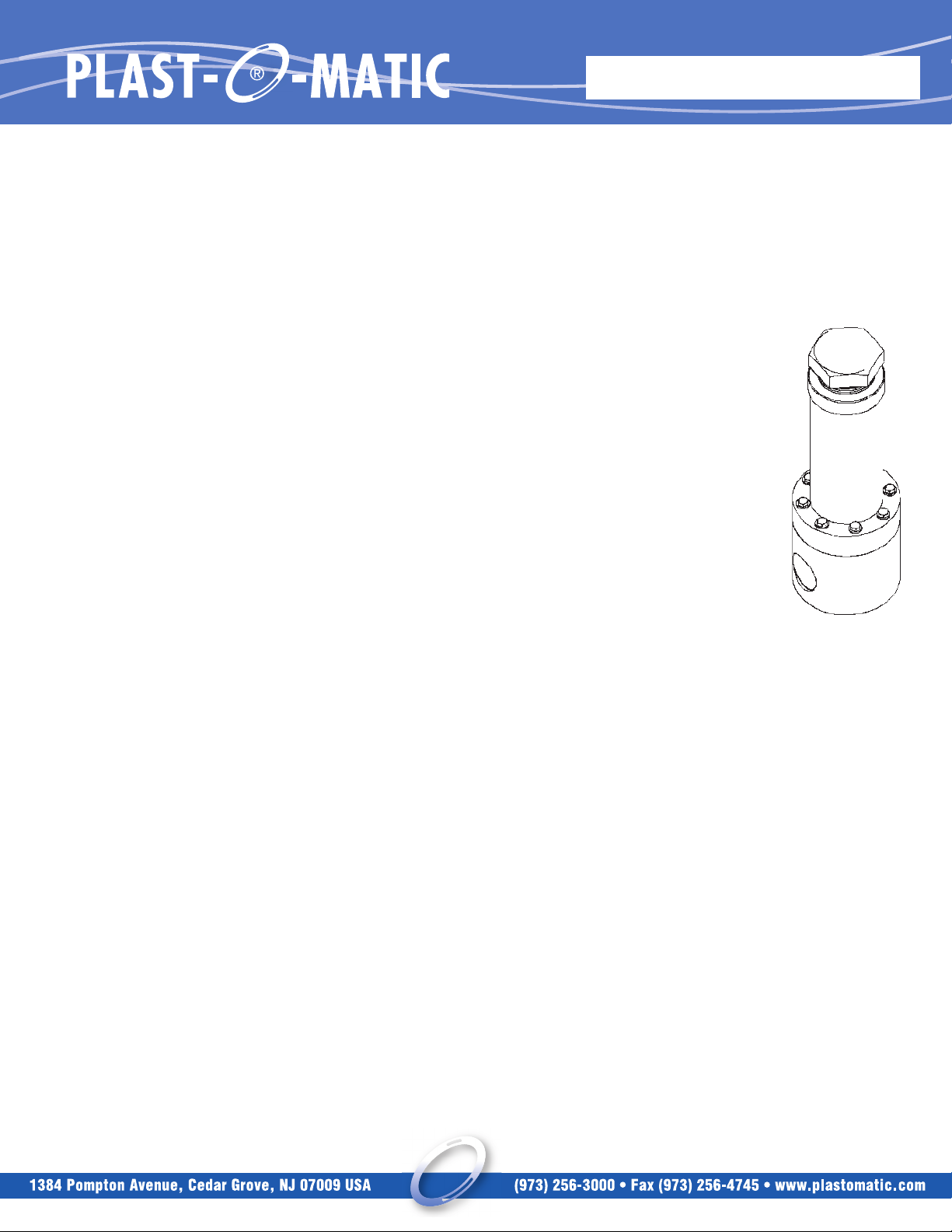
D. PARTS & ILLUSTRATION
#QTY. DESCRIPTION MAT’L
11BODY see B.3. on page
1
21SPRING HOUSING PVC
31LOCK RING HDPE
41ADJUSTING SCREW HDPE
51DIAPHRAGM SUPPORT PVC
61U-CUP SEAL VITON FKM
74HEX HEAD SCRW SS
84LOCK WASHER SS
9XSPRING(S) see table next pg STEEL
10 1 SEALING DIAPHRAGM PTFE
11 1 BACKING DIAPHRAGM VITON FKM
Exact appearance varies by size and/or body style.

INSTRUCTIONS
A. Seal Kits – Plast-O-Matic recommends keeping a spare seal kit
available for repairs. Seal life will vary in applications due to cycles,
temperatures, pressures, chemicals, and concentration. Based on
the application, a periodic inspection and maintenance plan should
be established. The part number for a seal kit is SK plus the valve
part number less the material suffix. for example, RVDT050V-PV
needs a seal kit SKRVDT050V.
B. Changing Range of Adjustment – Range of pressure adjustment can
be changed by changing or combining springs. Unscrew the
adjusting screw all the way and remove. Add or remove springs.
Replace the adjusting screw.
PART NO. PIPE SIZE ADJUST RANGE SPRINGS
RVDT025T 1/4˝ 5-40 LC112L-2
41-100 LC112L-2
& LC112J-5
RVDT050T 1/2˝ 5-50 LC135M-0
51-100 LC135M-0
& LC112J-4
RVDT075T 3/4˝ 5-50 LHC162N-0
51-100 LC112J-7
& LHC162N-0
RVDT100T
OR 1˝ 5-100 LC135M-3
RVDTM100T
LHC234T-2
RVDT150T 1
1
⁄2˝ 5-100 LHL200A-4
RVDT200T 2˝ 5-100 LHL100A-8
& LHL200B-4
TRUE BLUE™ PTFE DIAPHRAGM
RELIEF VALVES RVDT/RVDTM
ASSEMBLY, INSTALLATION & OPERATING INSTRUCTIONS
D. MAINTENANCE
RVDT-614
 Loading...