

Page 1
k
TM
Raidtec FS3102
Raidtec FS3102
Raidtec FS3102Raidtec FS3102
Quick Start Guide
Version 1.2
Default IP Address:
Note: In the event of the FS3102 being connected to a networ
without DHCP enabled, use the Default IP Address for initial
connection to the network. This IP address may be changed using
Raidtec Manager
System S/N:
MAC Address:
Subnet Mask:
TM
after successful connection of the system.
Contact Plasmon
255.255.0.0
Sales and Marketing Global Technical Support
European Headquarters
Plasmon Data Limited,
Whiting Way,
Melbourn,
Hertfordshire,
SG8 6EN,
U.K.
mailto:[email protected]
http://www.plasmon.com/
Plasmon and Raidtec are registered trademarks of Plasmon Plc. Copyright 2006
http://www.plasmon.com/raid
Tel: +44 (0) 1763 262 963
mailto:[email protected]
Page 2

Raidtec FS3102 Quick Start Guide
Raidtec FS3102 Quick Start Guide
Raidtec FS3102 Quick Start GuideRaidtec FS3102 Quick Start Guide
Unpacking the FS3102
The following items are included in your FS3102 package. Check the packing list before
installation to ensure that you have received each item. If you are missing any item, please
contact your Plasmon reseller.
FS3102 Enclosure x 1
(Up to 12 depending on capacity)
Drive Shuttle
5m Fibre Optic Cable x 2 SFP x 2
Ethernet Cable x 1 PSU Cable x 2 (Country Specific)
Raidtec Manager CD x 1 Rack Mount Kit x 1
Dummy Drive Shuttle - for empty bays
2
Page 3
Raidtec FS3102 Quick Start Guide
Raidtec FS3102 Quick Start Guide
Raidtec FS3102 Quick Start GuideRaidtec FS3102 Quick Start Guide
Installing Disk Drives
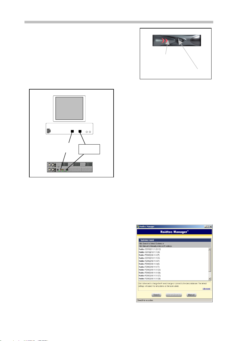
Slide the Lock Release Button to the right to release
the drive tray handle, see Figure 1. Using the Drive
Tray Handle, insert the drive tray into the bay with the
disk facing up. Push the drive tray into the bay until
you feel some resistance, and then close the Drive
Drive Tray Handle
Tray Handle to lock it in place. Ensure that all disks
are fully inserted and locked in. RAID volumes could
be inaccessible or in a degraded state if any disk is
Lock Release Button
not seated correctly.
Figure 1 – Lock release mechanism
Host
Host
Computer
Computer
Connecting to a host system
Disk Access
The Raidtec FS3102 system has two 2Gb
Fibre Channel (FC) ports. For optimum
performance, use a 2Gb FC Host Bus
Ethernet
Serial cable
cable
Ethernet
Ethernet Net work
Network
Ethernet
cable
VHDCI - HD68
Fibre
SCSI Cable
Cable
CS3102
Figure 2 – Connecting to a host
Adaptor (HBA) in the host computer.
Connect one or both ports on the FS3102 to
a host system using the fibre optic cable(s)
provided, see Figure 2. Alternatively, the
FS3102 may be connected to multiple host
computers using a Fibre Channel Switch.
Administration
The Raidtec FS3102 is managed through an Ethernet connection. Connect the Raidtec
FS3102 to the network using the Ethernet cable provided. Any PC on the network that has
Raidtec Manager installed can manage the Raidtec FS3102.
Raidtec Manager™
Installation
Insert the Raidtec Manager CD into your CD drive.
If it does not autoload, open the CD root folder and
open the install.htm file to run the Installation.
Select Start Installer for <OS> to install the
software. When the installation has completed you
may run Raidtec Manager from the Start Menu.
Searching the Network
The first screen allows you to find all FS3102 and
CS3102 systems the network. Click on Search to
find the system(s); or, if you know the IP address,
you may enter it manually by clicking on the Manual
button (see Figure 3).
Figure 3 – System Search Screen
3
Page 4
Raidtec FS3102 Quick Start Guide
Raidtec FS3102 Quick Start Guide
Raidtec FS3102 Quick Start GuideRaidtec FS3102 Quick Start Guide
Default IP Settings
By default, the FS3102 is configured to use DHCP for assigning IP addresses. If DHCP is
not enabled and no IP address has been assigned previously, the Raidtec FS3102 system
will use the Default IP Address shown on the cover of this document. This Default IP
Address is intended for temporary use only. If DHCP is not being used, we strongly
recommend that you set the IP address to a permanent address on the local subnet.
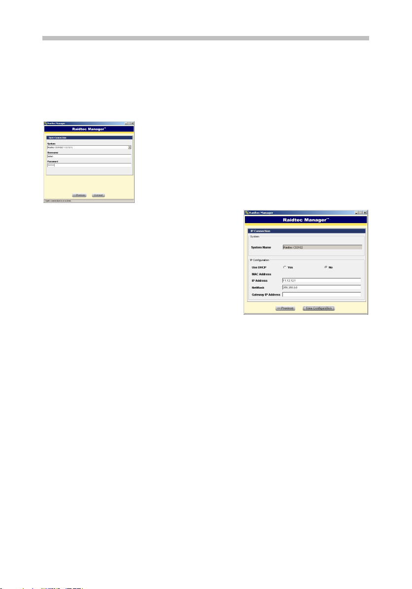
Open Connection Screen
After selecting a system from the Search screen or entering
the IP address of the system manually, you must open a
connection to the system. For your first connection, use
“admin” for both Username and Password. When this default
password is entered, the system will go to the Setup Wizard
screen where you can set up your network and
administration settings.
Figure 4 – Open Connection
IP Connection Screen
If you fail to connect to your chosen system, you
will be asked if you want to go to the IP Connection
Screen. Here you may reconfigure the IP settings
for the system. When you do this and click on
Save Configuration you will return to the System
Search Screen where you should see your system
at the bottom of the list.
Figure 5 – IP Connection Screen
Default RAID Configuration
The Raidtec FS3102 system comes pre-configured with one disk reserved as a global spare
and the remaining disks at RAID level 5 with the File Server profile. This configuration has
one Logical Volume of 10GB, which needs to be mapped to the HBA of the host computer.
The capacity of this Logical Volume may be expanded, as required. All caching options are
enabled (caching options can be changed without deleting the RAID). If a different RAID
configuration is required, this RAID may be deleted.
Note: It is highly recommended that one disk be reserved as a global spare to allow an
automatic rebuild of the RAID in the event of a disk failure.
4
Page 5
Raidtec FS3102 Quick Start Guide
Raidtec FS3102 Quick Start Guide
Raidtec FS3102 Quick Start GuideRaidtec FS3102 Quick Start Guide
Logical Volume Mapping
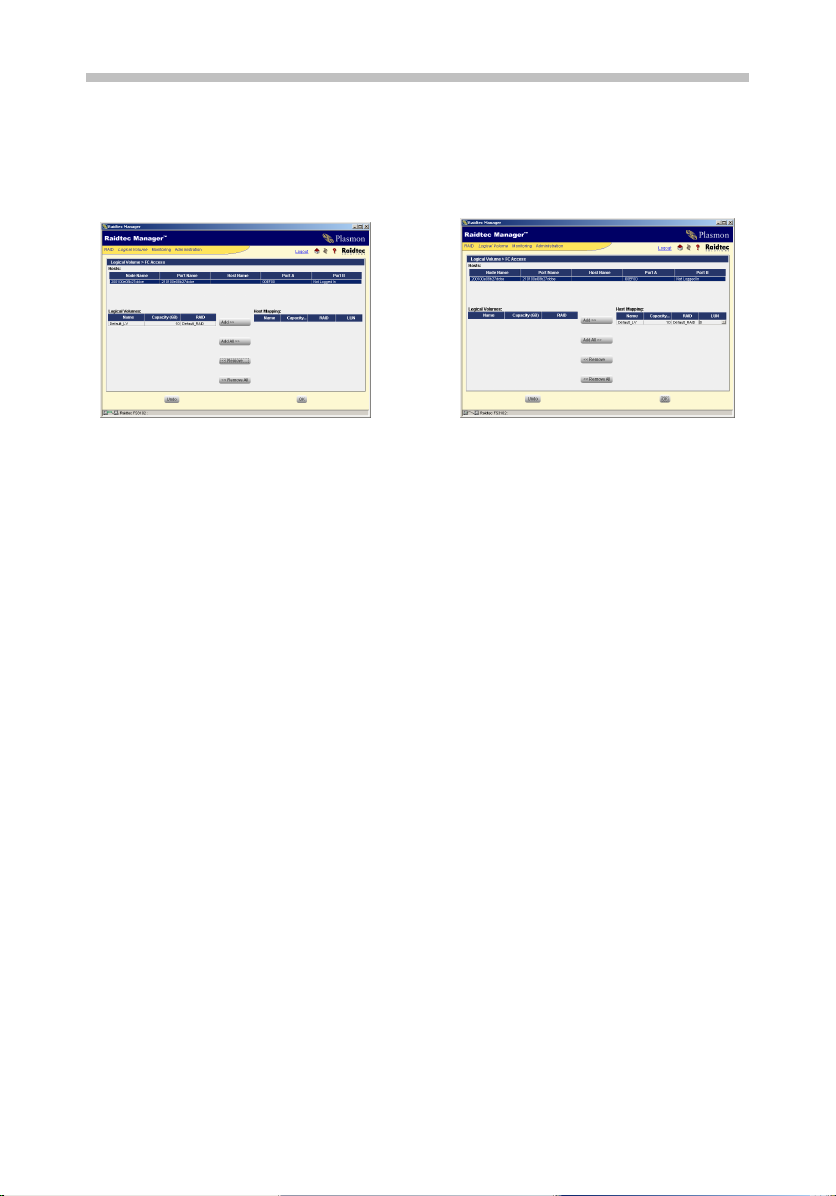
You can map the default Logical Volume to the host computer by selecting FC Access in the
Logical Volume drop down menu. Any Host HBAs visible to the FS3102 will appear in the
Hosts table and the Logical Volume will appear in the Logical Volumes table. There will be
no entry in the Host Mapping table.
Æ
Firstly, select a Host HBA for which you want to define a mapping. Then select the Logical
Volume from the Logical Volumes table, click on the Add button to move it to the Host
Mappings table and click OK to save the new mapping. Repeat the process for each Logical
Volume to be mapped to this Host HBA.
Repeat the mapping procedure for further HBAs, as required.
Please refer to the User Guide on the accompanying Administrator CD for detailed
system set-up.
Figure 6 – Logical Volume Mapping
5
 Loading...