

Page 1

5.2GB
Magneto Optic
Disk Drive
User Manual
Page 2

European Headquarters
Plasmon Data Limited
Whiting Way
Melbourn
Hertfordshire SG8 6EN
Tel +44 (0)1763 262963
Fax +44 (0)1763 264444
Email: [email protected]
United States
Plasmon
4425 ArrowsWest Drive
Colorado Springs CO, 80907-3489
Tel (719) 593-7900
Fax (719) 599-8713
Page 3
User Manual
Copyright
Copyright 1998, Plasmon Data Limited.
© No part of this publication may be reproduced, stored in a retrieval
system, or transmitted, in any form or by any means, without the
prior written consent of Plasmon.
Trademarks
TM All trademarks that may be contained within this publication are
registered with their respective companies.
Changes
The material in this manual is for reference only and is subject to
change without notice.
While reasonable efforts have been taken in the preparation of the
material contained in this manual, Plasmon assumes
no liability resulting from any errors or omissions, or from the use
of material contained herein.
Cautions
The following images are designed to draw your attention to
important information within this manual:
NOTE - Information relating to important suggestions.
CAUTION - Warnings relating to directions which could put the
operator and drive at risk of damage.
TIP - Hints to achieve the optimum performance from your drive.
Release November 2002
97705153 A
i
Page 4
FCC Compliance Statement
NOTE:This equipment has been tested and found to comply with the
limits for a Class B digital device, pursuant to part 15 of the FCC
rules. These limits are designed to provide reasonable protection
against harmful interference in a residential installation. This
equipment generates, uses and can radiate radio frequency energy
and, if not installed and used in accordance with the instructions,
may cause harmful interference to radio communications.
However, there is no guarantee that interference will not occur in
a particular installation. If this equipment does cause harmful
interference to radio or television reception, which can be
determined by switching the equipment off and on, the user is
encouraged to try to correct the interference by one or more of the
following measures:
Reorient or relocate the receiving antenna.
User Manual
Increase the separation between the equipment and receiver.
Connect the equipment into an outlet on a circuit different from
that to which the receiver is connected.
Consult the dealer or an experienced radio/TV technician for help.
The compliance of this unit to the FCC rules is not subject to any
special accessories, which are not readily available through normal
dealer channels.
The drive is in conformity with the EMC directive and low-voltage
directive.
CAUTION:Any modifications or changes made to this equipment not
expressly approved by the PLASMON group of companies may void the
authority to operate this equipment in its intended installation.
ii
97705153 A
Page 5
User Manual
Laser Product
Class 1 Laser Product
The optical drive mechanism contained in this unit is certified to
comply with DHHS rule 21 CFR Chapter 1, Sub-chapter J in effect as
of the date for manufacture.
This optical drive mechanism is classified as a Class 1 laser product
to EN 60825, and there is no hazardous laser radiation with the
safety protection.
Use of controls or adjustments or performance of procedures other
than those specified herein may result in hazardous radiation
exposure.
Never open the enclosure or touch the parts internal to the
product.
When the power switch is on, do NOT place your eyes close to the
front panel opening to look into the unit.
Laser Specification
Class 1 LASER mechanism
Laser Power: No hazardous radiation is emitted with the safety
protection of the unit.
97705153 A
iii
Page 6

Unpacking / Packing
(1) General precautions
Note the following precautions in order to maintain the
performance and reliability of the drive.
! Open the package with particular care.
! Do not expose the unit to excessively dusty environment.
! The unit contains components that can be destroyed by static
electricity.
Follow the guidelines below for internal unit:
! Use an anti-static mat and ground yourself when handling the
internal unit.
! Always be sure to handle the internal unit only by the frame and
do not touch any electrical components.
User Manual
(2) Unpacking (Internal Unit)
When moving the unit to an environment where there is a
significant difference in temperature, let the unit remain in its
packaging for at least two hours.
Find a flat, soft surface for unpacking, keeping the box upright.
Do not apply excessive force to the unit when removing the shockabsorbing material, or to the surfaces and interface connector
when removing the anti-static bag.
(3) Unpacking (External Unit)
When moving the unit to an environment where there is a
significant difference in temperature, let the unit remain in its
packaging for at least two hours.
Find a flat, soft surface for unpacking, keeping the box upright.
iv
97705153 A
Page 7
User Manual
(4) Packing
Pack the unit after you have removed the disk.
Put the device in the anti-static or plastic bag.
It is desirable to use the original shock-absorbing material and
packing box used when the unit was delivered to you. If not, use
a box with a shock-absorbing structure that will prevent direct
impacts to the device. In the case of the internal unit, protect
the surfaces and interface connector against possible damage and
use an anti-static bag.
(5) Transportation
!Transport the unit in a well-packaged condition, with the upside
facing up.
! Transport the unit as little as possible after unpacking, always
using the shock absorbing material to avoid impact and vibration.
When carrying the unit after unpacking, keep it in the horizontal
plane.
(6) Storage
• Use the moisture-proof packing material for storage.
• The storage environment should meet the non-operating
environmental requirement as specified in Appendix E.
! Do not expose the unit to radical changes in temperature, which
could cause condensation.
97705153 A
v
Page 8

User Manual
vi
97705153 A
Page 9

User Manual
Table of Contents
Copyright. . . . . . . . . . . . . . . . . . . . . . . . . . . . . . . . . . . . . . . . . . . . . . . i
Trademarks. . . . . . . . . . . . . . . . . . . . . . . . . . . . . . . . . . . . . . . . . . . . . i
Changes . . . . . . . . . . . . . . . . . . . . . . . . . . . . . . . . . . . . . . . . . . . . . . . i
Cautions. . . . . . . . . . . . . . . . . . . . . . . . . . . . . . . . . . . . . . . . . . . . . . . i
FCC Compliance Statement. . . . . . . . . . . . . . . . . . . . . . . . . . . . . . . . . . . ii
Laser Product. . . . . . . . . . . . . . . . . . . . . . . . . . . . . . . . . . . . . . . . . . . iii
Class 1 Laser Product. . . . . . . . . . . . . . . . . . . . . . . . . . . . . . . . . . . . iii
Laser Specification. . . . . . . . . . . . . . . . . . . . . . . . . . . . . . . . . . . . . iii
Unpacking / Packing. . . . . . . . . . . . . . . . . . . . . . . . . . . . . . . . . . . . . . . iv
Owners Record. . . . . . . . . . . . . . . . . . . . . . . . . . . . . . . . . . . . . . . . . . . 2
Warning . . . . . . . . . . . . . . . . . . . . . . . . . . . . . . . . . . . . . . . . . . . . . . 2
General Description . . . . . . . . . . . . . . . . . . . . . . . . . . . . . . . . . . . . . . . 3
SCSI Connections. . . . . . . . . . . . . . . . . . . . . . . . . . . . . . . . . . . . . . . . . 4
SCSI Identifier. . . . . . . . . . . . . . . . . . . . . . . . . . . . . . . . . . . . . . . 6
General Precautions for MOD520E. . . . . . . . . . . . . . . . . . . . . . . . . . . . . . 7
GETTING STARTED. . . . . . . . . . . . . . . . . . . . . . . . . . . . . . . . . . . . . . . . . 8
Operation & Installation Instructions. . . . . . . . . . . . . . . . . . . . . . . . . 8
External Drive. . . . . . . . . . . . . . . . . . . . . . . . . . . . . . . . . . . . . . . . 8
Internal Drive. . . . . . . . . . . . . . . . . . . . . . . . . . . . . . . . . . . . . . . . 9
Prechecks before Service Call. . . . . . . . . . . . . . . . . . . . . . . . . . . . . . . . 10
Placing a service call. . . . . . . . . . . . . . . . . . . . . . . . . . . . . . . . . . . . . . 10
Service on the unit. . . . . . . . . . . . . . . . . . . . . . . . . . . . . . . . . . . . . . . 11
Microsoft Optical Systems and Optical Support. . . . . . . . . . . . . . . . . . . . . 11
Disk Cartridge Notes. . . . . . . . . . . . . . . . . . . . . . . . . . . . . . . . . . . . . . 12
Appendix A. . . . . . . . . . . . . . . . . . . . . . . . . . . . . . . . . . . . . . . . . . . . 13
Component Location. . . . . . . . . . . . . . . . . . . . . . . . . . . . . . . . . . . . 13
Appendix B. . . . . . . . . . . . . . . . . . . . . . . . . . . . . . . . . . . . . . . . . . . . 15
Function Connector Pin Description. . . . . . . . . . . . . . . . . . . . . . . . . . 15
Appendix C. . . . . . . . . . . . . . . . . . . . . . . . . . . . . . . . . . . . . . . . . . . . 16
SCSI Device Address. . . . . . . . . . . . . . . . . . . . . . . . . . . . . . . . . . . . 16
Appendix D. . . . . . . . . . . . . . . . . . . . . . . . . . . . . . . . . . . . . . . . . . . . 17
Drive Option Switches. . . . . . . . . . . . . . . . . . . . . . . . . . . . . . . . . . . 17
Appendix E. . . . . . . . . . . . . . . . . . . . . . . . . . . . . . . . . . . . . . . . . . . . 18
Main Specifications. . . . . . . . . . . . . . . . . . . . . . . . . . . . . . . . . . . . 18
Appendix F. . . . . . . . . . . . . . . . . . . . . . . . . . . . . . . . . . . . . . . . . . . . . 19
SCSI Interface connector signal names. . . . . . . . . . . . . . . . . . . . . . . 19
MOD520E SCSI CONNECTOR. . . . . . . . . . . . . . . . . . . . . . . . . . . . . . . 19
MOD520I 50 WAY IDC CONNECTOR. . . . . . . . . . . . . . . . . . . . . . . . . . . 20
Appendix G. . . . . . . . . . . . . . . . . . . . . . . . . . . . . . . . . . . . . . . . . . . . 21
Accessories and Spares. . . . . . . . . . . . . . . . . . . . . . . . . . . . . . . . . . 21
Owners Record
97705153 A
1
Page 10

User Manual
Warning
The model and serial number of the drive you have just purchased
are located on the underside of the unit
below, and refer to them should you need to call your supplier for
service or technical support.
MOD520 Serial No.
Keep this manual for reference purposes should any switch setting
need to be altered.
Use of controls or adjustments other than those specified herein
may result in hazardous laser radiation exposure. This product may
only have the cover removed for service or repair by a qualified and
approved service site.
(1)
(External) or the top of the drive (Internal).
(1)
. Please record them
Air Filters
The MOD520E (external drive) is shipped without Air Filters. The drive
has been designed with ducted air cooling, air should not get into
the body of the drive. Air Filters are provided for particularly dusty
or dirty environments. (Please be advised that the drive will run up
to a maximum ambient temperature of 30°C with air filters).
2
97705153 A
Page 11

User Manual
General Description
The MOD520 is a high performance, high capacity optical disk drive
that offers recording on rewritable and CCW WORM media that is ISO
compliant. The MOD520 reads and writes to 5.2GB, 4.8GB, 4.1GB,
2.6GB and 2.3GB, rewritable, WORM and DOW disks and offers read
compatibility to earlier ISO standard 1.3GB, 1.2GB, 650MB and
600MB media so protecting any existing investment in storage.
The MOD520 also forms the basis for the M-Series range of Plasmon
Magneto Optic jukeboxes, providing further performance increases.
The MOD520 has been designed to give fast, solid and reliable disk
exchanges .
Please take the time to study this manual to become familiar with
operating the unit, as well as prescribed service.
The main features of the MOD520 drive are:
✓ 5.2GB (2.6GB per side) of storage on rewritable, and CCW
WORM disks.
✓ Half height unit.
✓ Reads 594MB and 650MB disks as well as 1.2GB, 1.3GB, 2.3GB
and 2.6GB media as used in earlier MO drives in addition to
read & write compatibility to 2.3GB and 2.6GB disks.
✓ Data cache of 4MB for write and read operations.
✓ Effective seek time of 25ms
✓ Synchronous data rates up to 10 Mbytes/sec.
✓ Universal AC supply operates from 100 to 240 volts (MOD520E).
97705153 A
3
Page 12
SCSI Connections
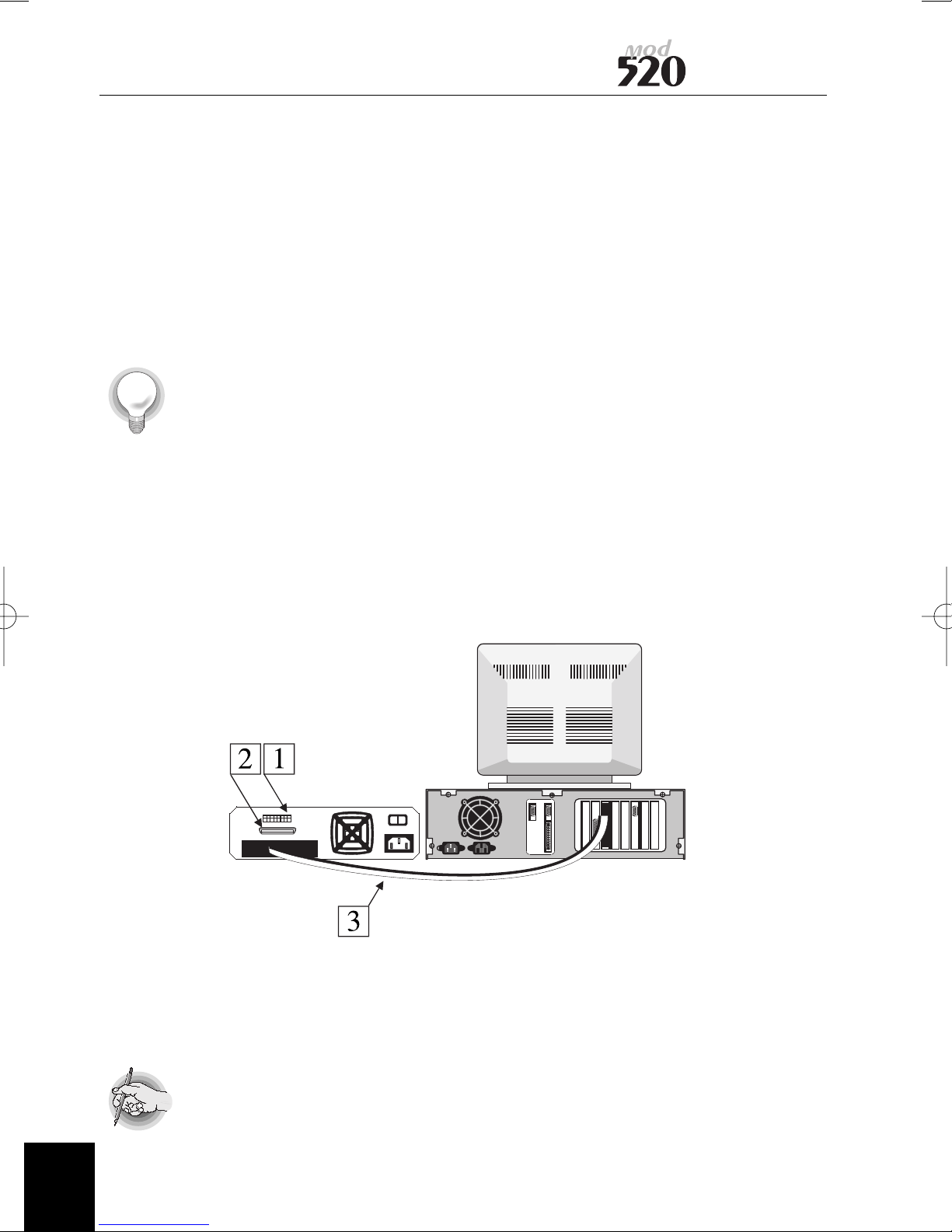
The external drive is equipped with two Micro D 50 way connectors
on the rear panel. These are for the SCSI in and SCSI out (if there
are additional devices connected).
A SCSI interface cable needs to be terminated at each end of the
line, one terminator being on the last device in the chain and the
other terminator is usually on the host computer or adapter card,
a Micro D SCSI Terminator is supplied (external drive only).
Refer to the documentation supplied with your SCSI card or
computer system should you need to check the computer
termination. In normal circumstances this will usually be enabled.
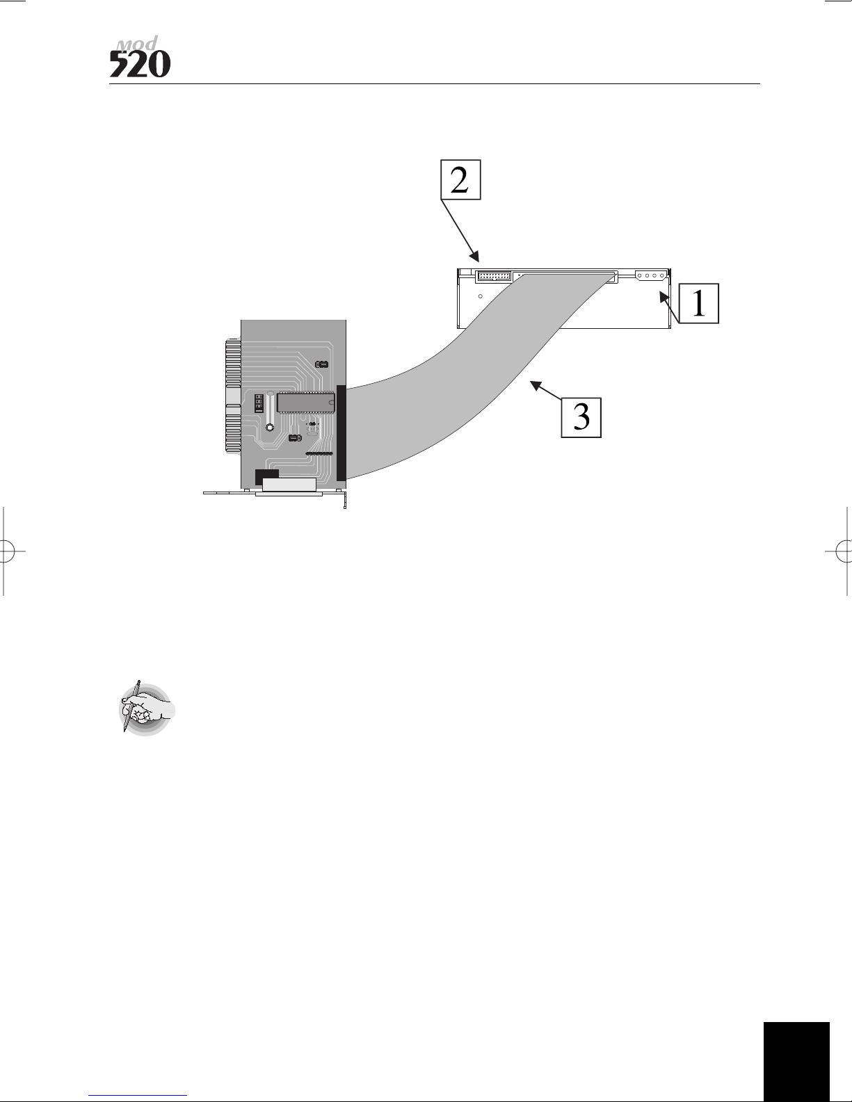
The two ways of connecting SCSI devices are shown below :
Fig 1.External Drive Connection
Fig 2.Internal Drive Connection
User Manual
Fig 1 External Drive Connection
1.Switch block SCSI ID setting
2.SCSI connector for additional devices or terminator if last in chain.
3.SCSI cable
If there are also internal devices on the same SCSI card, then the
SCSI adapter card must have its on-board termination disabled.
4
97705153 A
Page 13
User Manual
Fig 2 Internal Drive Connection
1. DC Power Connector
2. Jumper block for SCSI ID settings
3. 50 way SCSI cable - note pin 1 orientation
If internal devices are also to be connected to the SCSI card, then
the SCSI adapter on-board termination must be disabled. Refer to
the documentation that accompanies the SCSI adapter.
97705153 A
5
Page 14

SCSI Identifier
Each device on a SCSI bus requires a unique address to be set which
maybe in the range of 0 to 6 as address 7 is usually reserved for the
host computer address. The MOD520 is shipped with a default
address of 1 which will usually suffice in most cases.
Please refer to diagram on Appendix C
User Manual
6
97705153 A
Page 15

User Manual
General Precautions for MOD520E
✗ Never plug or un-plug any connectors or cables from the
device on the SCSI bus whilst power is applied to either host
computer or any devices attached.
✗ Do not use the unit under the following operating
environments :
Places with high humidity
Exposed to direct sunlight
Locations subject to excessive shock or vibration
✗ Do not cover ventilation slots as these are provided for cooling.
✗ Do not place the drive near a printer.
✗ Never attempt to disassemble the unit.
✗ Never touch the surface of a recordable disk.
✗ Do not allow any foreign object or liquid to enter the unit.
✓ Always remove the disk before moving the unit. This will
ensure that the optical head is securely positioned for shipping.
✓ Keep the packaging material should the unit have to be
transported.
Additional Notes for Internal Models
✗ Never connect / disconnect unit to / from SCSI bus with
power on any units including host computer.
✓ When handling the unit, an anti-static wrist strap should be
used to avoid possible damage from static electricity.
✓ Ensure that the power connector is correctly wired.
✓ Check that the power is within the unit’s specification.
✓ Ensure that adequate ventilation is provided.
97705153 A
7
Page 16

GETTING STARTED
Operation & Installation Instructions
External Drive
Do not apply power yet!
Set the SCSI ID of the unit via the DIP switch on the rear of the
unit.
Connect the SCSI interface cable between the computer and the
drive unit.
If the drive is the last unit on the SCSI interface, install the
supplied terminator in the unused SCSI connector.
Apply power to the unit.
User Manual
Notes:
Insert a disk cartridge into the drive, gently pushing it into the
drive until it is power loaded. The motor will start and after a few
seconds the drive will be ready for use.
When the eject button is pressed the cartridge will electronically
eject from the drive after a short delay.
If you need to use the emergency eject pinhole, make sure that
the unit is powered off and that the disk has stopped its rotation
(20-30 seconds after power off).
If the SCSI ID is changed with the unit powered ON, then power
must be removed and reapplied for the new ID to take effect.
Before moving the drive, always ensure that the optical disk
cartridge is removed.
The drive has various functions that may be altered from their
defaults if required. These are outlined in the MOD520I section.
Opening the enclosure and changing these settings must only be
carried out by a qualified service engineer.
8
9775153 A
Page 17
User Manual
Internal Drive
! The drive must only be used in the horizontal plane.
• Attaching screws are supplied with the unit. The screws are M3 x
4 mm, and the fixing plate should be within the range of 1.5 to
2.5 mm, which includes the washer.
• Included with internal drives is a 50-way flat IDC cable with 2
connectors for connection to the SCSI adapter.
Note for correct orientation of the flat cable when installing! Pin 1 is
usually identified by a red stripe on the edge of the cable, and
connectors have a small arrow by pin 1.
! Connect the internal power connector in your computer to the
drive making sure that the orientation is correct.
97705153 A
9
Page 18
Prechecks before Service Call
1. Disk cannot be inserted.
? Is power on?
? Is the disk orientated correctly?
? Is the disk the correct type?
2. Access Failure
? Is the cartridge inserted?
? Is the SCSI ID set correctly?
? Are the SCSI bus terminated correctly?
? Is the cartridge set to write protect?
? Are other devices on the SCSI bus operating normally?
? Is the software device driver installed correctly?
Placing a service call
User Manual
Contact your supplier or service company. They will probably require
the following information;
Where purchased
Date of Purchase
Serial Number
Description of failure
System information which may include;
? Computer type and SCSI adapter type
? Software configuration (in DOS this will be the CONFIG.SYS
and AUTOEXEC.BAT file)
? Type of device driver being used
Software and Driver Updates
Do you have the latest revisions?
Contact your supplier for firmware or driver updates.
10
97705153 A
Page 19
User Manual
Service on the unit
There is no prescribed service for the unit. However, to ensure
optimum performance, the unit should operate in as clean an
environment as possible where contaminants do not enter the unit.
Should the unit require cleaning, do NOT attempt to open the drive,
but contact your supplier.
Microsoft Operating Systems and Optical support
Microsoft have confirmed that their NT operating system versions
3.51 and 4.0 do not currently FULLYsupport any WORM or Rewritable
Optical media (512,1024 or 2048 bytes per sector) or drives under
Fat or NTFS File Systems.
NT using FAT or NTFS, only supports Optical if the drive and media act
as a Magnetic Hard Drive. (Type 0 Device)
Windows NT will support both WORM and Rewritable Optical media
when used with another File System (such as Plasmon Drive Manager
for NT).
FAT and NTFS with full Optical support are being looked into for a
future release of NT from Microsoft.
Microsoft have committed that Windows 95 will read and write
Rewritable Optical media only when it has been formatted with
third party software. WORM media is not supported and requires
third party software.
Customers using NT with Plasmon Multitasking Manager have no
needfor any action.
For details of Optical support in future products from Microsoft,
please contact them direct.
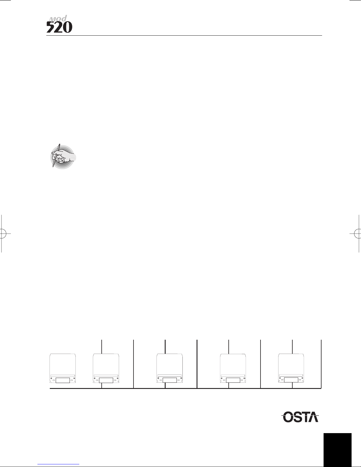
Magneto Optic Technology Roadmap
650
MB
1993 1994 1995 1996 1997 1998 1999 2000
97705153 A
1.3
GB
2.6
GB
5.2
GB
9.1
GB
June 1997
11
Page 20
Disk Cartridge Notes
1. Never open the shutter to look at the disk. The shutter is
provided for protection against dust, dirt and other
contaminants.
2. Avoid subjecting the cartridge to sudden shock or impact.
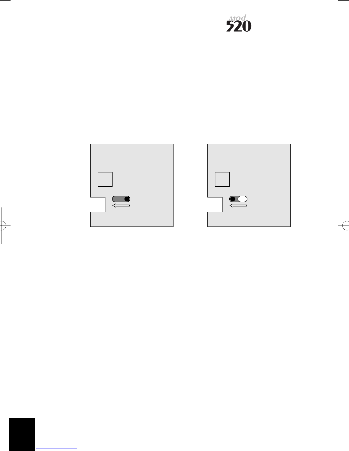
3. When the write protect window is open, the disk is in a read
only mode of operating.
User Manual
Read write enable Write protect
12
97705153 A
Page 21
User Manual
Appendix A
Component Location
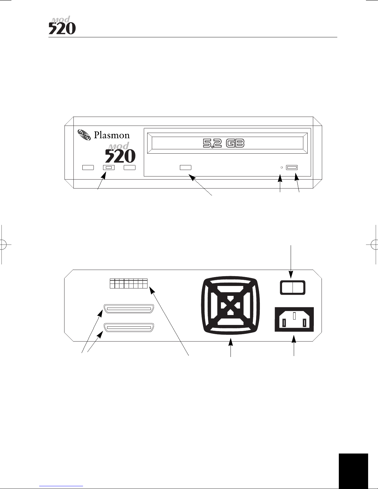
MOD520E
B
A = Busy indicator
B = Power light
C = Cartridge eject
D = Emergency eject
A = SCSI connectors
B = SCSI ID selector
C = Fan (optional filter)
D = Power connector
E = AC on / off switch
A
D
C
E
DCBA
97705153 A
13
Page 22
Appendix A (continued)
Component Location
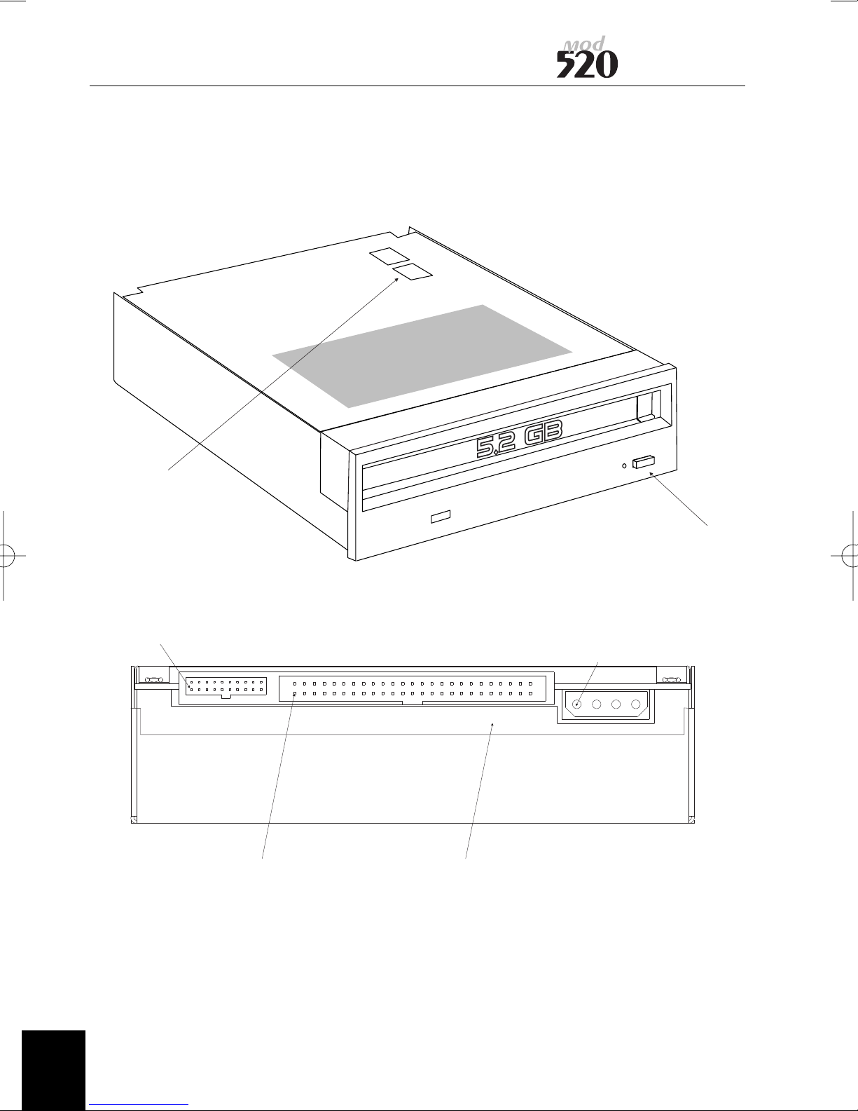
MOD520I
User Manual
OPTION SWITCHES
FUNCTION ON PIN 1
(Appendix B&C)
SCSI PIN 1 FLAP FOR AIR DUCTING
EJECT BUTTON
PIN 1
14
97705153 A
Page 23
User Manual
User Manual
Appendix B
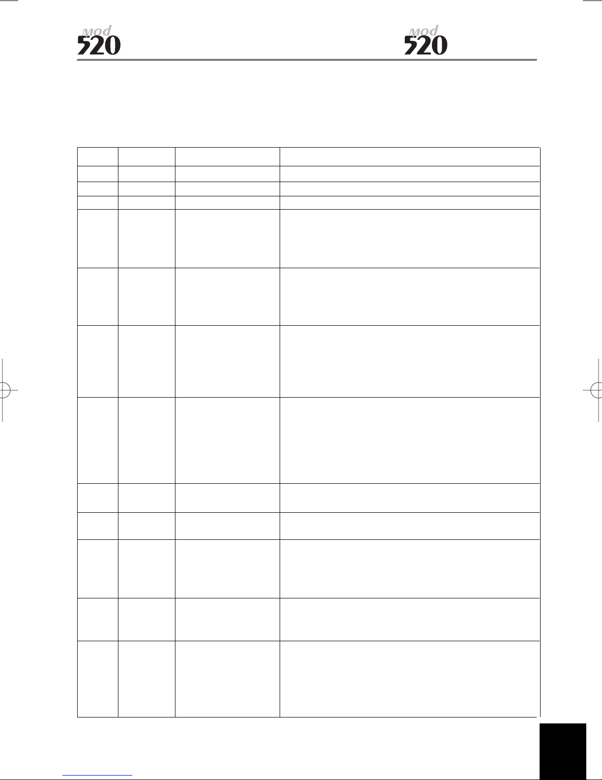
Function Connector Pin Description
(see appendix A for connector location)
SwitchPins Function Description
3 A1 - B1 SCSI ID 2 See Appendix C to set SCSI ID
2 A2 - B2 SCSI ID 1 See Appendix C to set SCSI ID
1 A3 - B3 SCSI ID 0 See Appendix C to set SCSI ID
A4 - B4 Disable SCSI When the pair of pins is open, the drive
Parity performs SCSI parity checking (default).
Shorting the pins with a jumper forces the
drive NOT to perform the SCSI parity checking.
A5 - B5 Disable Write When the pair of pins is open, the drive
Cache performs write back caching (default).
Shorting the pins with a jumper forces the
drive NOT to perform the write back caching.
A6 - B6 Disable Auto When the pair of pins is open, the drive
Spin-up performs an automatic spin-up upon media
loading (default). Shorting the pins with a
jumper forces the drive NOT to perform the
automatic spin-up.
4 A7 - B7 Force Verify Shorting the pair of pins forces the drive to
for Write perform a Write and Verify operation
whenever the host issues a WRITE command
(default). Opening the pins by removing the
jumper will force the drive not to Verify after
Write (unless specified under software
A8 - B8 Disable Manual Shorting the pins disables the eject button
Eject operation. (Default Open).
5 A9 - B9 Enable Fast SCSIShorting the pins enables Fast SCSI mode.
Default Closed
6 A10 - B10 Device Type When the pins are open the drive responds as
an Optical Memory Device (type 7) (Default).
Shorting the pins forces the drive to respond
as a Direct Access Device (type 0)
A11 - B11 Enable Shorting the pins invokes the internal SCSI
Termination active terminator. With the pins open
(default) Termination is disabled.
A12 - B12 Terminator These pins supply +5V DC through an isolation
Power diode for SCSI terminator power to the SCSI
bus TERMPWR line. Shorting the pins enables
SCSI TERMPWR signal (default). Leaving them
open disables.
97705153 A
15
Page 24
Appendix C
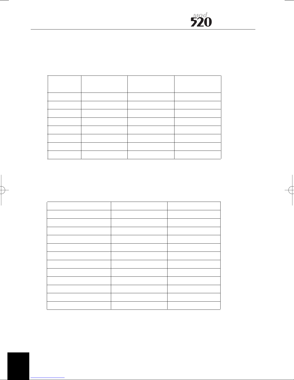
SCSI Device Address
Jukebox Connector SCSI ID
SCSI Drive JP3 or SW3 JP2 or SW2 JP1 or SW1
Address
0 OFF OFF OFF
1 OFF OFF ON
2 OFF ON OFF
3 OFF ON ON
4 ON OFF OFF
5 ON OFF ON
6 ON ON OFF
7 ON ON ON
User Manual
Drives are set up to ID1 as default
Default Jumpers on external and internal units
Jumper/Switch internal external
JP1/SW3 N/C OFF
JP2/SW2 N/C OFF
JP3/SW1 Fitted ON
JP4 N/C N/C
JP5 N/C N/C
JP6 N/C N/C
JP7/SW4 Fitted ON
JP8 N/C N/C
JP9/SW5 Fitted ON
JP10/SW6 N/C OFF
JP11 N/C N/C
JP12 Fitted Fitted
16
97705153 A
Page 25
User Manual
Appendix D
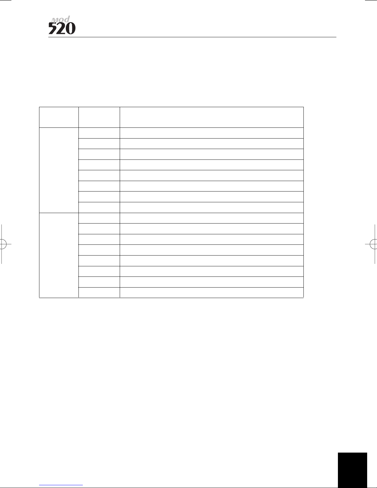
Drive Option Switches
The MOD520 provides eight switches, which permit the user to define certain drive
operations or interface features.
Optional Switch Description
Switch Number
1 Reserved
2 Reserved
3 Disable Command Eject
S501 4 Reserved
5 Enable Library I/F Mode
6 Reserved
7 Disable Write Cache
8 Disable Auto Spin-up
1 Reserved
2 Reserved
3 Reserved
S502 4 Reserved
5 Disable SCAM Selection
6 Reserved
7 Reserved
8 Enable Write Cache for Write and Verify Command
Option Switch Function
NOTE:The MOD520I is shipped with the forced verify on write operation enabled.
NOTE:The drive is shipped with write caching enabled by default. In data critical
applications it may be necessary to disable write caching. This may be achieved using
Adaptecs “SCSI EXPLORER” program under the windows environment. Programmers
may also access this function through the Mode Page Settings.
97705153 A
17
Page 26

Appendix E
Main Specifications
Access times
Average seek (1⁄3full stroke)
Motor start
Motor stop
Rotational speed
Data transfer rates
User sustained write/read
Burst asynchronous
Burst synchronous
MOD520e MOD520i
25 ms
2.5 seconds
2.2 seconds
3300/3600 RPM
2.48 to 5.07 MB/second
3 MB/second
10 MB/second (Fast SCSI enabled)
25 ms
2.5 seconds
2.2 seconds
3300/3600 RPM
2.48 to 5.07 MB/second
3 MB/second
10 MB/second (Fast SCSI enabled)
User Manual
Buffer size
MTBF (Power On Hours)
Environmental
Operating temperature
Non-operating temperature
Operating humidity
Non-operating humidity
Operating vibration (5-350Hz)
Operating shock (no damage)
Non-operating shock
Electrical
Operating voltage
Power requirements
Structure
Dimensions (WxHxD in mm)
Weight
Drive orientation
Warranty
4 MB
100,000
+5 to +40°C
-30 to 60°C
10 to 90%
5 to 90% non condensing
0.00015 G
2
Hz or 0.014 m2/s
3
30G or 294 m/s2, 3ms half sine
2
89G or 873 m/s
, 3ms half sine
100 to 240V AC; 50/60Hz
0.5A
228 x 66 x 276
3.9 Kg
horizontal/vertical
one year parts and labour
RTB
4 MB
100,000
+5 to +40°C
-30 to 60°C
10 to 90%
5 to 90% non condensing
0.00015 G
2
Hz or 0.014 m2/s
3
30G or 294 m/s2, 3ms half sine
2
89G or 873 m/s
, 3ms half sine
+5V ± 5%; 12V + 5%
+5V @ 2.0A (Max); 0.8A (Typ)
12V @ 3.0A (Max); 0.9A (Typ)
146 x 41.3 x 203
1.5 Kg
horizontal/vertical
one year parts and labour
RTB
Appendix F
18
97705153 A
Page 27
User Manual
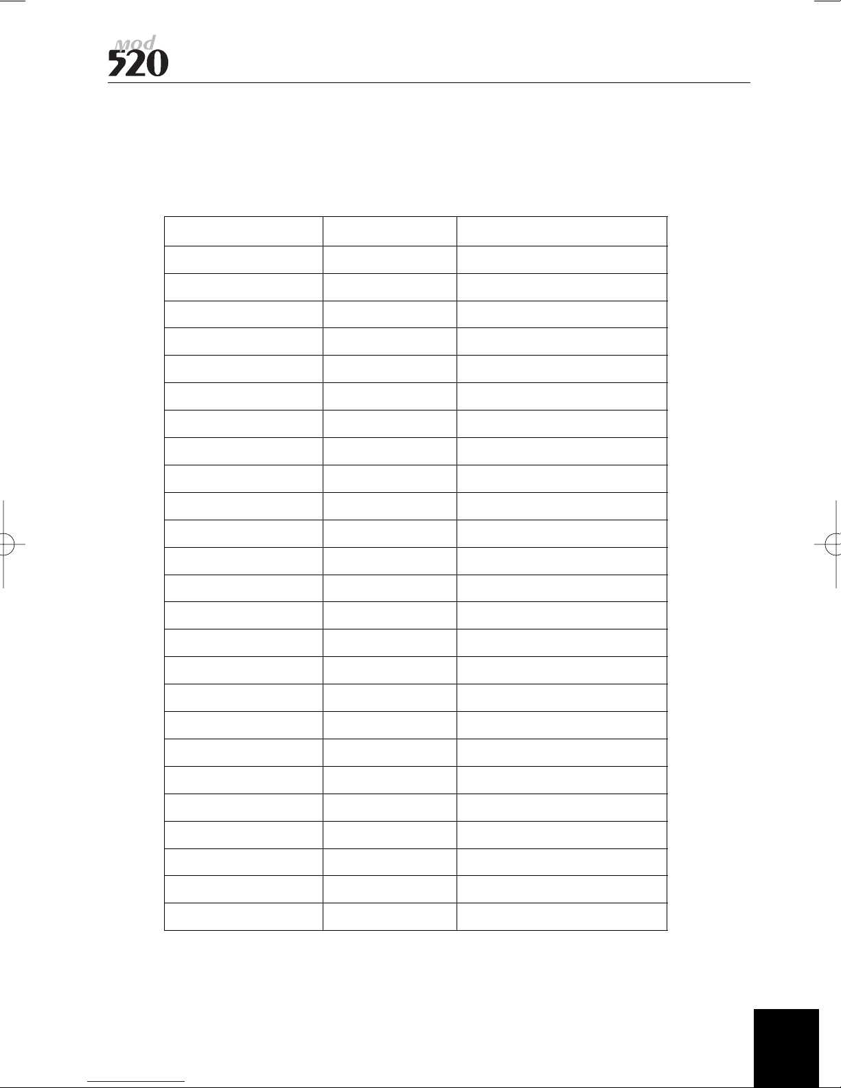
SCSI Interface connector signal names
MOD520E SCSI CONNECTOR
SIGNAL NAME PIN NUMBER SIGNAL SOURCE
DB0 26 SCSI HOST /CONTROLLER
DB1 27 SCSI HOST /CONTROLLER
DB2 28 SCSI HOST /CONTROLLER
DB3 29 SCSI HOST / CONTROLLER
DB4 30 SCSI HOST /CONTROLLER
DB5 31 SCSI HOST /CONTROLLER
DB6 32 SCSI HOST /CONTROLLER
DB7 33 SCSI HOST /CONTROLLER
DBP 34 SCSI HOST /CONTROLLER
GROUND 35
GROUND 36
GROUND 37
TERMPWR 38 SCSI HOST /CONTROLLER
GROUND 39
GROUND 40
ATTN 41 SCSI HOST
GROUND 42
BSY 43 SCSI HOST /CONTROLLER
ACK 44 SCSI HOST
RST 45 SCSI HOST
MSG 46 CONTROLLER
SEL 47 SCSI HOST /CONTROLLER
C / D 48 CONTROLLER
REQ 49 CONTROLLER
I / O 50 CONTROLLER
SCSI Interface connector signal names
97705153 A
19
Page 28
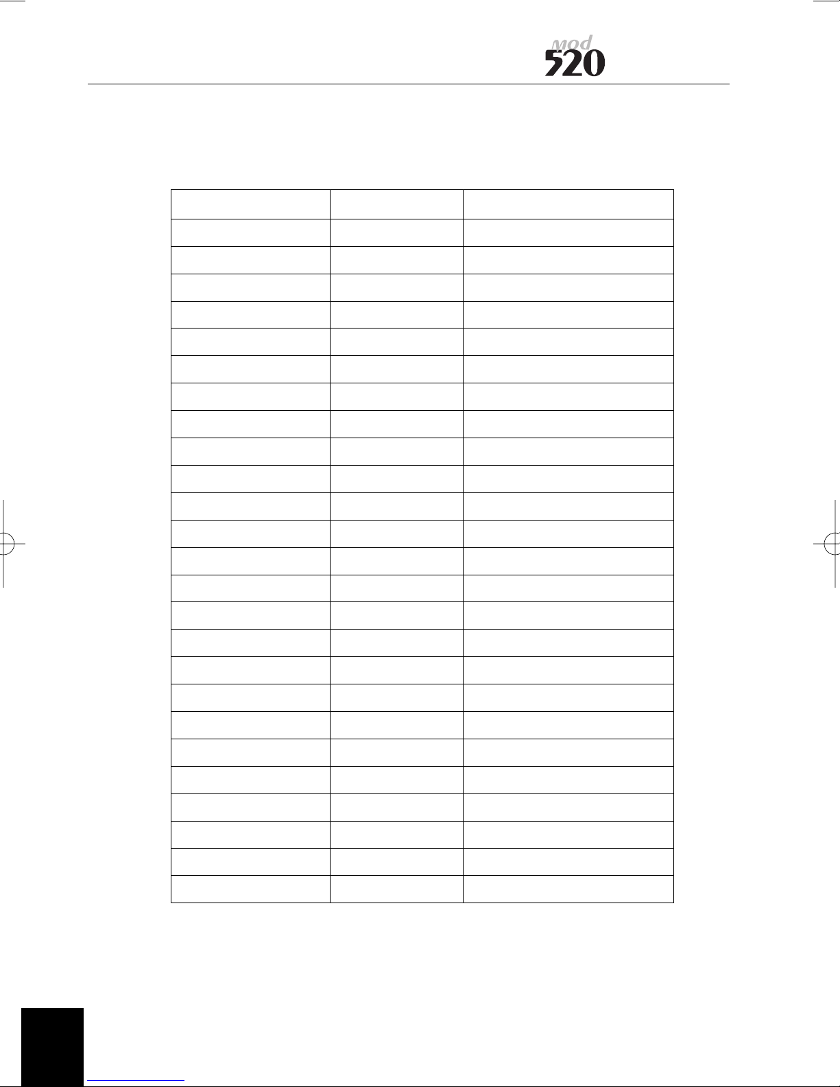
MOD520I 50 WAY IDC CONNECTOR
SIGNAL NAME PIN NUMBER SIGNAL SOURCE
DB0 2 SCSI HOST /CONTROLLER
DB1 4 SCSI HOST /CONTROLLER
DB2 6 SCSI HOST /CONTROLLER
DB3 8 SCSI HOST /CONTROLLER
DB4 10 SCSI HOST /CONTROLLER
DB5 12 SCSI HOST /CONTROLLER
DB6 14 SCSI HOST /CONTROLLER
DB7 16 SCSI HOST /CONTROLLER
DBP 18 SCSI HOST /CONTROLLER
GROUND 20
User Manual
GROUND 22
GROUND 24
TERMWR 26 SCSI HOST /CONTROLLER
GROUND 28
GROUND 30
ATTN 32 SCSI HOST
GROUND 34
BSY 36 SCSI HOST /CONTROLLER
ACK 38 SCSI HOST
RST 40 SCSI HOST
MSG 42 CONTROLLER
SEL 44 SCSI HOST /CONTROLLER
C / D 46 CONTROLLER
REQ 48 CONTROLLER
I / O 50 CONTROLLER
20
97705153 A
Page 29

User Manual
Appendix G
Accessories
Media
P5200W 5.2GB WORM MO media (2048 bytes/sector)
P5200E 5.2GB Rewritable MO media (2048 bytes/sector)
P4800W 4.8GB WORM MO media (1024 bytes/sector)
P4800E 4.8GB Rewritable MO media (1024 bytes/sector)
P4100E 4.1GB Rewritable MO media (512 bytes/sector)
97705153 A
21
Page 30

Notes
User Manual
22
97705153 A
Page 31

Contacting Plasmon
Should there be a need for further support other than what this
manual provides, please contact one of these two technical
support locations:
To obtain technical support in the United States
Plasmon
Technical Support
e-mail [email protected]
World Wide Web www.plasmon.com
1-877-585-6793
1-719-593-4192 (fax)
To obtain technical support in Europe
Plasmon Technical Support +44 (0) 1763 262 963
+44 (0) 1763 264 444
e-mail [email protected]
World Wide Web www.plasmon.com
International Calls 1-719-593-4437
1-719-593-4192 (fax)
Page 32

 Loading...