

Plasmon LF6600 User Manual
THE PLASMON INFINITY
LF 6600
OPTICAL DISK DRIVE
User Manual
P/N 97653976 F

New features and changes to information in this document are indicated by change bars. Revision level is
indicated by the letter following the eight-digit document number. If a document has undergone major
modifications, change bars will not be inserted in the document.
Reproduction of this manual, or any portion of this manual, is prohibited without the express permission of
Plasmon Laser Magnetic Storage (LMS). Plasmon LMS reserves the right to make changes in this
document and the product referred to herein without prior notice.
© 1999 Plasmon Laser Magnetic Storage

WARNING
Always observe the following when installing, operating or maintaining
this product:
• This unit must be connected to a power distribution system that has a
direct connection to earth ground (Terminated Terra [TT] network/
ground connected). This unit is not suitable for use on a floating
ground (Interrupted Terra [IT]) network.
• The AC input power cord must be shielded and must have a minimum
current rating of 10 A with a nominal cross-section area of 0.75 sq mm
(reference: AWG #18) per conductor, 2 wires plus ground and product
safety approvals as required for use in the country in which the unit is
installed.
• When the unit is mounted in an equipment rack or cabinet, be certain
that the internal temperature within the rack or cabinet does not
exceed the limits defined in the Product Specification or this
document.
• To ensure the integrity of safety features of this unit, maintenance must
be performed only by qualified service personnel using designated
Plasmon LMS parts.
• In case of fire or other emergency, isolate the units from the main
power by disconnecting the power plugs from their site power
receptacles. In situations where disconnecting the plugs is not
possible or practical, use the system main power disconnect to isolate
the units from the main power.
• To prevent fire or shock hazard, do not expose this unit to rain or
moisture. Refer servicing to qualified technicians.

(German Translation)
Bei der Installation, Bedienung und Wartung dieses Produkts, bitte
immer die folgenden Vorsichtsmaßnahmen treffen:
• Dieses Gerät muß an ein Stromversorgungssystem angeschlossen
werden, das direkt mit einem Erdungsanschluß verbunden ist
(Terminated- Terra-Netz [TT]/mit Erdanschluß). Dieses Gerät kann
nicht an ein ungeerdetes Netz (Interrupted Terra [IT]) angeschlossen
werden.
• Die Verbindungsschnur des Wechselstromeingangs muß entstört sein
und ihr Minimalstrom unter folgenden Bedingungen bei 10 A liegen:
Der Nennquerschnitt beträgt 0,75 mm je Leiter (Referenz: American
Wire Gauge Nr. 18), es bestehen 2 Drähte plus ein Erdanschluß und
das Produkt entspricht den im Land, in dem es aufgestellt wird,
geltenden Sicherheitsvorschriften.
WARNING
• Wird das Gerät in ein Gerätegestell oder einen Geräteschrank
eingebaut, ist darauf zu achten, daß die interne Temperatur im Gestell
oder Schrank nicht über die in den Produktspezifikationen oder
diesem Dokument angegebenen Grenzwerte hinausgeht.
• Um ein ordnungsgemäßes Funktionieren der Sicherheitsmerkmale
dieses Gerätes zu gewährleisten, dürfen Wartungsarbeiten nur von
qualifiziertem Fachpersonal ausgeführt werden. Es sind darüber
hinaus nur Ersatzteile zu verwenden, die von der Firma Plasmon LMS
angegeben werden.
• Im Falle eines Feuers oder in einem anderen Notfall sind die Geräte
vom Hauptnetz zu trennen, indem die Netzstecker aus den
Steckdosen am Einbauort gezogen werden. Ist ein Herausziehen der
Stecker nicht möglich oder zu umständlich, trennen Sie die Geräte mit
Hilfe des System- Hauptnetzabschalters vom Hauptnetz.
• Um Feuer- oder Stromschlaggefahr zu vermeiden, ist dieses Gerät
niemals Regen oder Feuchtigkeit auszusetzen. Wartungsarbeiten
sind qualifiziertem technischen Personal zu überlassen.

RADIO/TV INTERFERENCE (USA)
The information in this section applies only to units in use within the United States:
This equipment generates and uses radio frequency energy and, if not installed and used properly, that is,
in strict accordance with the manufacturer's instruction, may cause interference to radio and television
reception. It has been type tested and found to comply with the limits for a Class A computing device in
accordance with the specifications of Part 15 of FCC Rules, which are designed to provide reasonable
protection against such interference in a residential installation. However, there is no guarantee that
interference will not occur in a particular installation. If this equipment does cause interference to radio or
television reception, which can be determined by turning the equipment off and on, the user is encouraged
to try to correct the interference by one or more of the following measures:
• reorient the receiving antenna
• relocate the equipment away from the receiver
• plug the equipment into a different outlet so that equipment and receiver are on different branch
circuits.
If necessary, the user should consult the dealer or an experienced radio/television technician for additional
suggestions. A pamphlet by the FCC ‘How to Identify and Resolve Radio-TV Interference Problems' is
available from the US Government Printing Office, Washington, D.C., 20402, Stock No. 044-000-00345-4.
CDRH COMPLIANCE
LF 6600 contains a Class 1 Laser Product. This product complies with 21CFR Chapter 1, Subchapter J,
applicable at date of manufacture.
CANADIAN EMI COMPLIANCE
Canadian Department of Communications standards require that the following statement appear in
operating manuals for any digital apparatus imported into Canada:
This digital apparatus does not exceed the Class A limits for radio noise for digital apparatus set out in the
Radio Interference Regulations of the Canadian Department of Communications.
FRENCH TRANSLATION
Cet équipement digital ne dépasse pas les limites de la Classe A pour les interférences radioélectriques
des systémes digitaux fixées par les Réglements concernant les Interférences Radioélectriques établis par
le Ministére des Communications du Canada.
All Plasmon LMS products comply with the requirements of this standard.
Agency Compliance and Approval
For details on Agency Compliance and Approval refer to the LF 6600 Product Specification Manual.


TABLE OF CONTENTS
SCOPE 9
RELATED PUBLICATIONS 9
GENERAL DESCRIPTION 11
DRIVE CHARACTERISTICS 13
FRONT PANEL 15
REAR PANEL 16
DIMENSIONS AND WEIGHT 17
SHIPPING WEIGHT 17
TEMPERATURE, HUMIDITY AND ALTITUDE 18
SHOCK AND VIBRATION 19
AC POWER REQUIREMENTS 19
AC GROUND 20
AC POWER CORD 20
POWER SUPPLY OUT-OF-RANGE PROTECTION 20
TILT RANGE 20
HEAT DISSIPATION 20
PARTICULATE LIMITS 20
WARNING LABELS 21
UNPACKING AND REPACKING INSTRUCTIONS 23
UNPACKING THE TOWER CONFIGURATION 23
UNPACKING THE RACK MOUNT CONFIGURATION 26
INSPECTING THE LF 6600 28
REPACKING THE LF 6600 28
CLOSING THE BASEPLATES 29
REPACKING THE TOWER CONFIGURATION 30
REPACKING THE RACK MOUNT CONFIGURATION 31
INSTALLATION AND DE-INSTALLATION 33
INSTALLATION REQUIREMENTS 33
TOWER INSTALLATION 34
RACK MOUNT INSTALLATION 35
SCSI BUS CONSIDERATIONS 48
CONNECTING POWER AND SCSI CABLES 50
CONNECTING THE POWER CORD 51
CONNECTING MULTIPLE DEVICES 51
CONNECTING A SINGLE DEVICE 52
CONNECTOR VERIFICATION 53
RACK MOUNT CONFIGURATION DE-INSTALLATION 54

OPERATING INSTRUCTIONS 57
CONTROLS AND INDICATORS 57
POWER-ON PROCEDURE 59
MODES OF OPERATION 60
OPERATING MODE 60
CONFIGURATION MODE 62
TEST MODE 84
MEDIA CARTRIDGE HANDLING 85
SETTING THE WRITE PROTECTION SWITCH 87
AFFIXING LABELS 88
MEDIA INSERTION AND REMOVAL 88
MANUAL CARTRIDGE RELEASE MECHANISM 92
MEDIA LOADING 96
OPERATOR MAINTENANCE 97
INSPECTING AND CLEANING FAN AND BLOWER FILTERS 97
REPLACING FUSES 98
MEDIA CLEANING 100
MEDIA CLEANING USING
CLEANING KIT P/N 97662550 100
ACCESSORIES 101
APPENDIX A 105
GERMAN TRANSLATIONS/
ÜBERSETZUNGEN INS DEUTSCHE 105

SCOPE
This User Manual describes unpacking, installing, operating, and maintaining the Plasmon LF 6600
RapidChanger High-Performance Optical Disk Drive.
RELATED PUBLICATIONS
Publication Part Number
LM 6000 Media Product Specification 97647044
LD 6100/LF 6600/LF 6602 Product Specification 97653977
LD 6100/LF 6600/ LF6602 SCSI Interface Specification 97653978
LD 6100 Hardware Maintenance Manual 97653979
LF 6600/LF 6602 Hardware Maintenance Manual 97653980
LD 6100 User Manual 97654437
WARRANTY STATEMENT
The LF 6600 is warranted as stated in the purchase agreement between Plasmon and it’s customer,
or the Plasmon sales order acknowledgment, whichever is applicable.
The Plasmon LMS quality system is in compliance and registered to ISO 9001. The LF 6600 is
manufactured from new parts, or remanufactured parts.
LF 6600 warranty does not cover defects or damage caused by the use of unauthorized parts or
repairs or improper use or maintenance. Repairs or replacements not covered by the warranty will
be invoiced at LMS’ then current prices.
The warranty is void when installation, service or repairs are performed by unauthorized
personnel; when the product is affected by unauthorized alterations, modifications or other
tampering or misuse; when the product is incorporated into a system which causes or involves
any changes in the physical, mechanical or electrical arrangement of the product; or when the
product is not used in accordance with its applicable specifications.
The term, authorized personnel, is defined as those persons who have been trained by Plasmon
LMS Technical Services.
97653976 F
Page 9

PLASMON LASER MAGNETIC STORAGE - LF 6600 User Manual
Page 10
GENERAL DESCRIPTION
The LF 6600 RapidChanger is a write once read many (WORM), high-capacity optical disk drive with an
integral shuttle capable of holding up to six LM 6000/LM 4000 media cartridges. The integral shuttle moves
laterally to position one of six media cartridges for automated loading and unloading into the optical drive.
The LF 6600 RapidChanger provides up to 12 GBytes of online storage or up to 72 GBytes nearline
storage.
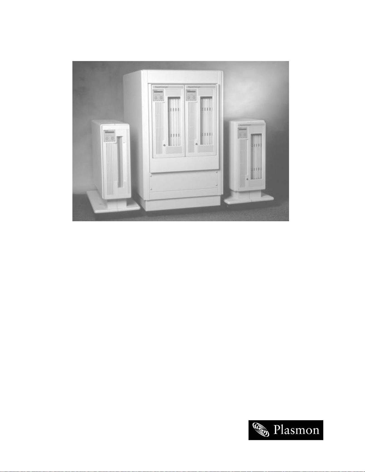
The LF 6600 is available in either a Rack Mount or Tower configuration. Two LF 6600 Rack Mount drives
can be mounted side-by-side in an EIA standard 19-in. rack. The Tower is a standalone LF 6600 that can
be located on an open floor or beside a desk.
RACK MOUNT
CONFIGURATION
TOWER
CONFIGURATION
EP006023
EP006024
LF 6600 Configurations
A Drive Operator Console (DOC) located on the front panel of the drive provides user control of drive
operation and configuration as explained in the operator section of this manual. Operating messages are
presented on the alphanumeric display in English, French or German. The language used is selectable.
The front panel includes a lockable media access door to provide operator access to the shuttle and media
cartridges.
The Auxiliary Diagnostic Port (ADP), located on the rear panel of each drive, can be used to download
updates to the drive firmware in the field. Refer to the LD 6100/LF 6600/LF 6602 Product Specification
(P/N 97653977) for more information.
The LF 6600 supports a sustained read transfer rate of 2.7 MBytes/sec with error correction and defect
management capabilities to maintain data integrity and manage media flaws. The LF 6600 supports a
sustained write transfer rate of 1.3 MBytes/sec with data verification.
97653976 F
Page 11

The LF 6600 implements the Small Computer System Interface (SCSI) via standard SCSI-2 micro-
connectors located on the rear panel. Single-ended and differential interface options are available, and
the interface can be changed in the field. Both the single-ended and differential controllers support
asynchronous or synchronous data transfer operations.
Preventive maintenance for the LF 6600 is minimal (refer to Operator Maintenance section of this manual).
Corrective maintenance is simplified by internal diagnostic firmware which detects, isolates and reports
malfunctions to the operator and identifies the Field Replaceable Unit (FRU).
LM 6000 media is interchangeable between the LF 6602, LF 6600 and the LD 6100.
The 6000 series of drives will also read LM 4000 media written by the Plasmon LMS 4000 series of optical
drive products (except for media with serial numbers less than X0010000, where X designates an A or B).
PLASMON LASER MAGNETIC STORAGE - LF 6600 User Manual
Page 12
DRIVE CHARACTERISTICS
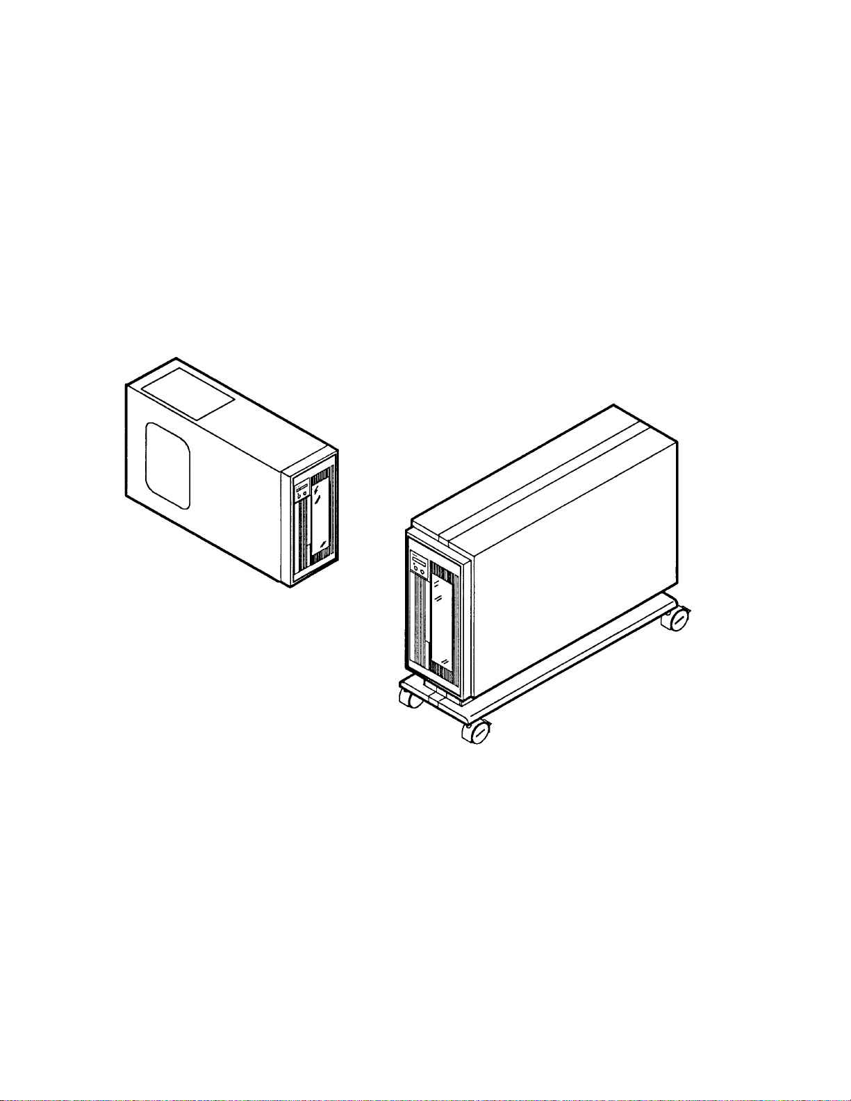
The LF 6600 Rack Mount and Tower configurations use the same major assemblies (refer to the next two
figures).
LF 6600 Rack Mount Configuration
EP006023
97653976 F
Page 13
LF 6600 Tower Configuration
EP006024
PLASMON LASER MAGNETIC STORAGE - LF 6600 User Manual
Page 14
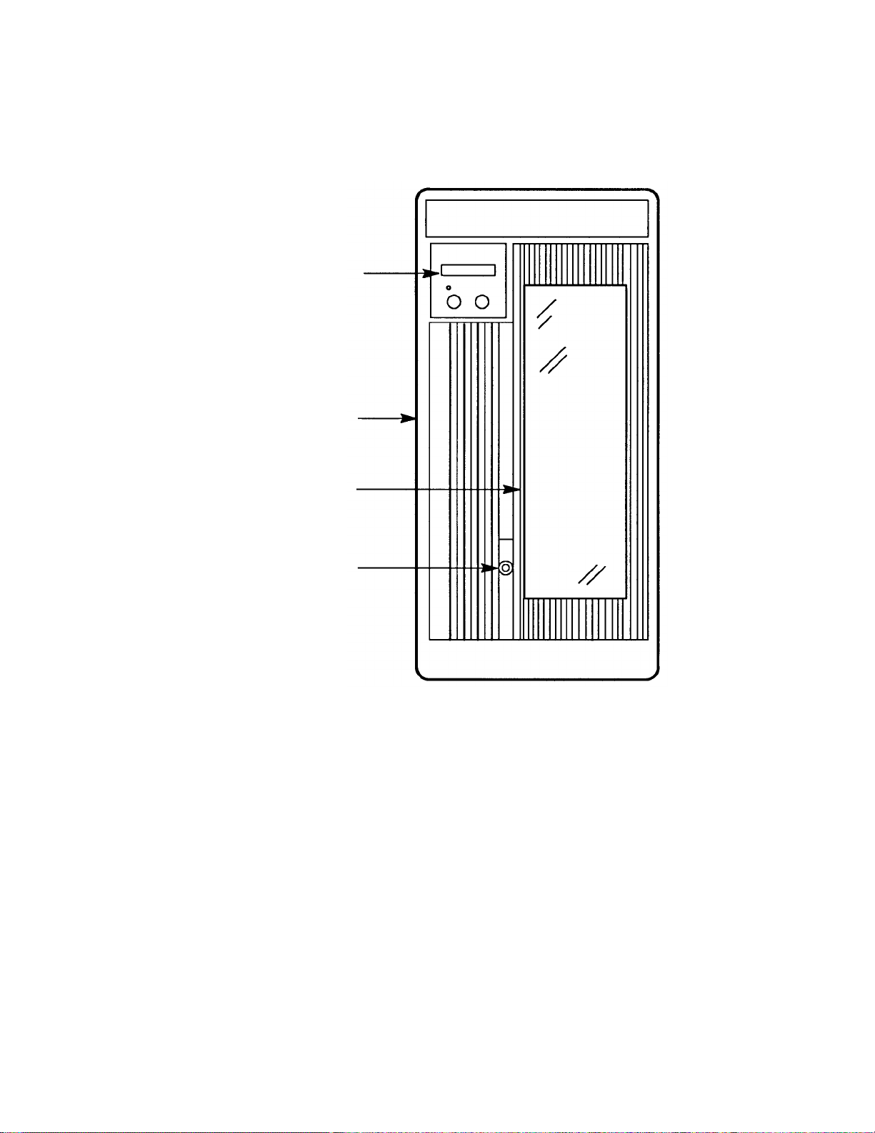
FRONT PANEL
The LF 6600 front panel (see figure below) includes a Drive Operator Console (DOC), media access door,
and door lock within a bezel assembly. Refer to the Operating Instruction section of this manual for a
detailed description of the DOC.
DOC
BEZEL
MEDIA ACCESS
DOOR
KEY LOCK
LF 6600 Front Panel
97653976 F
Page 15
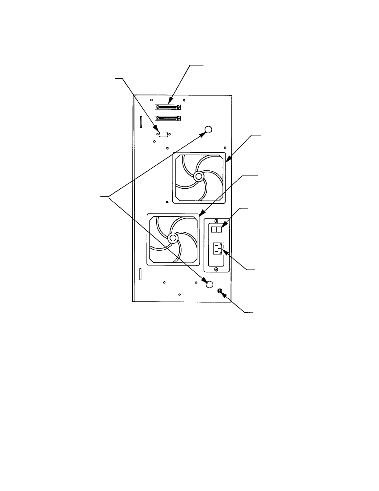
REAR PANEL
The LF 6600 rear panel contains the power switch along with AC power connector and fuses, the ground
connector, and external interface connectors.
AUXILLIARY
DIAGNOSTIC
PORT (ADP)
MANUAL
RELEASE
ACCESS
HOLES
SCSI-2 I/O
CONNECTOR
BLOWER GRILL
AND FILTER
ELEMENT
FAN GRILL AND
FILTER ELEMENT
AC POWER SWITCH
LF 6600 Rear Panel
AC POWER
RECEPTACLE
THREADED
GROUND
CONNECTOR
EP006013
PLASMON LASER MAGNETIC STORAGE - LF 6600 User Manual
Page 16

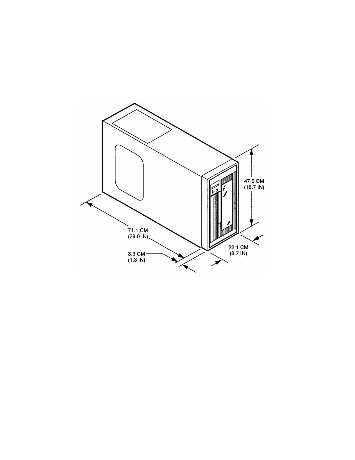
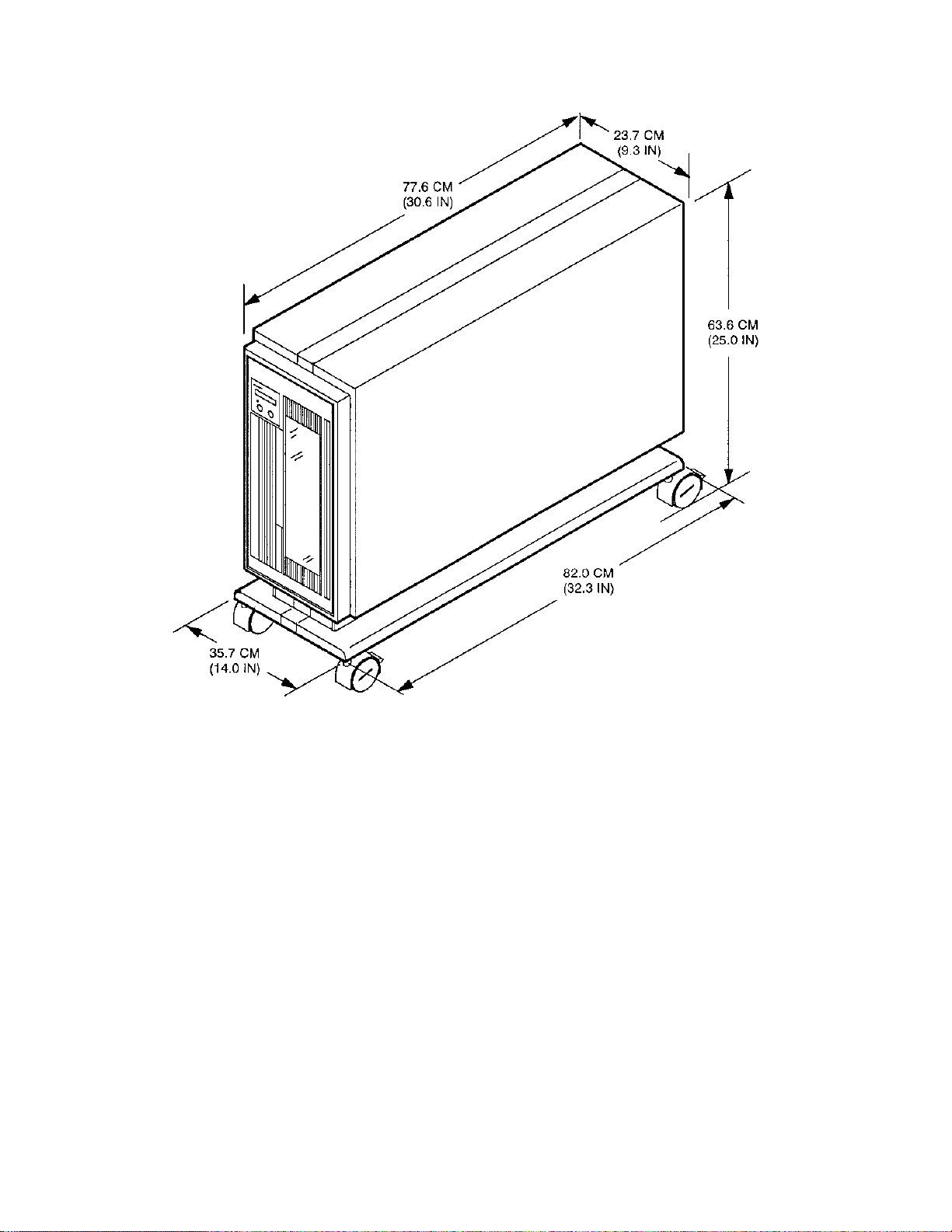
DIMENSIONS AND WEIGHT
The table below lists the reference dimensions of the LF 6600 configurations.
Dimensions of the LF 6600 Configurations
DIMENTION RACK MOUNT TOWER
Length 71.1 cm (28.0 in)
74.4 cm (29.3 in ) with Bezel
Width 22.1 cm (8.7 in)
includes Bezel
Height 46.7 cm (18.2 in)
47.5 cm (18.7 in) with Bezel
Mounting Depth 71.1 cm (28.0 in)
82.0 cm (32.3 in)
including Pedestal
35.7 cm (14.in)
including Pedestal
63.6 cm (25.0 in)
including Pedestal
SHIPPING WEIGHT
The LF 6600 shipping weight is listed below. These values do not include media cartridges.
Rack Mount: 44.1 kg (97 lbs)
Tower: 62.3 kg (137 lbs)
97653976 F
Page 17

TEMPERATURE, HUMIDITY AND ALTITUDE
The following table lists the LF 6600 operating, storage and transit limits for temperature, humidity and
altitude.
Temperature, Humidity and Altitude Limits
CONDITION OPERATING NONOPERATING
Temperature
Maximum Rate of
10 to 42° C
(50 to 108° F)
11° C/hr (20° F/hr) 20° C/hr (36° F/hr) 20° C/hr (36° F/hr)
2
-40 to 66° C
-40 to 151° F)
Change
Humidity
10 to 99% 5 to 95% 5 to 95%
(Noncondensing
Maximum Rate of
10%/hr 10%/hr 10%/hr
Change
Maximum Wet Bulb
Temperature
3
Minimum Dew Point
Altitude
4
28° C (82° F) 46° C (115° F) 46° C (115° F)
2° C (35.6° F) 2° C (35.6°0 F) 2° C (35.6° F)
Storage:
-300 to 3,000 m
(-984 to 9,840 ft)
-300 to 3,000 m
(0984 to 9840 ft)
STORAGE/TRANSIT
-40 to 66° C
-40 to 151° F)
Storage:
-300 to 3,000 m
(984 to 9,840 ft)
1
Transit:
-300 to 2,000 m
(-984 to 6,562 ft)
Transit:
-300 to 12,000 m
(-984 to 40,000 ft)
with media
1 Storage specifications are for 90 days maximum in Plasmon LMS packaging. No condensation is permitted. Transit specifications are
based on a maximum 1-week period in a factory-sealed container.
2 Maximum operating temperature is 42 _C for a free-standing drive at sea level unless otherwise stated. Maximum operating temperature
is derated linearly above 300 m altitude to 38 _C at 2,000 m altitude.
3 See the LD 6100/LF 6600/LF 6602 Product Specification (P/N 97653977) for more information concerning the temperature and humidity
operating range.
4 Media is limited to 2000 m. For conditions and limits pertaining to the media, refer to the LM 6000 Media Specification (P/N
97647044).
PLASMON LASER MAGNETIC STORAGE - LF 6600 User Manual
Page 18
SHOCK AND VIBRATION
The following table lists the conditions and limits for shock and vibration.
Shock and Vibration Criteria and Limits
CONDITION OPERATING
Swept Vibration
(Bidirectional)
1 Octave/Min
Shock
3
(Host Retries May
5 to 22 Hz 0.01 in
Double Amplitude,
22 to 500 Hz
10 - msec Half Sine
Pulse of 10.0 g Peak
0.25 g Peak
NONOPERATING
5 to 44 Hz, 0.03 in
Double Amplitude,
44 to 500 Hz
3.0 g Peak
4
1
STORAGE/TRANSIT
5 to 44 Hz, 0.03 in
Double Amplitude,
44 to 500 Hz
3.0 g Peak
Be Required and
Drive Performance
May Degrade During
Test
Unpacked (3 Axis) 5 - msec Half Sine
Pule of 20 g Peak
Packed on Pallet 46 - cm (18 - in)
Drop Test Flat
1 With media removed.
2 In LMS - approved packaging.
3 Shock repetition rate should be limited to allow mechanical system transients to subside between pulses.
4 For front - to - back axis, shock above 3.0 g peak will displace media from shuttle.
2
AC POWER REQUIREMENTS
The LF 6600 has a grounded power connector integrated into the AC power switch. Over current
protection is provided by two fuses integrated into the AC power switch. Two spare fuses are included
within the power connector. Refer to the Operator Maintenance section for the fuse replacement
procedure.
The drive's power supply accepts the input line voltages listed in the table below. The power supply is auto
ranging and does not require mechanical switching for input voltage or frequency selection.
AC Power Requirements
MINIMUM
SERVICE
RATINGS
FREQUENCY AC VOLTAGE
47 to 66 Hz 86.7 to 128 V 1.5 A 5.5 A 15 A
47 to 66 Hz 173.4 to 268 V 0.75 A 2.75 A 15 A
1 Less than 1 sec, cold start
After the power has been turned off, the operator must wait 1 second
before turning on the power again
CURRENT
(TYPICAL)
NOTE
SPIN - UP
SURGE
1
97653976 F
Page 19

AC GROUND
The LF 6600 chassis should be connected to earth ground for operator safety. The AC power cord has a
grounding conductor which connects the LF 6600 chassis to safety ground through the site AC power
system. If the site AC system ties its ground wire connection to earth ground, then the LF 6600 chassis will
also be tied to earth ground. All site AC power connections must be maintained on the same safety
ground.
A line grounding connector located on the rear panel can also be used to tie the LF 6600 chassis to earth
ground. This ground connector is a 6-mm (0.24-in.) M4 with a nut and lock washer.
AC POWER CORD
The type of AC power cord supplied with the LF 6600 will depend upon the configuration ordered.
POWER SUPPLY OUT-OF-RANGE PROTECTION FEATURES
The LF 6600 power supply provides over and under voltage protection, over current protection, power
failure detection and over temperature protection. Should an out-of-range condition be detected, the LF
6600 will shut down the DC outputs of the power supply. For example, if the internal temperature of the
power supply reaches 80° C +/- 5° C (176° F +/- 9° F), the power supply is shut down. After the situation
is corrected, power can be restored by turning the AC power switch to the off position and then to the on
position again.
TILT RANGE
The LF 6600 is not designed for use when tilted from the vertical position.
HEAT DISSIPATION
The drive will typically present a heat load of 146 kg-calories/hr (580 BTU/hr) during a read/write operation.
When media cartridges are inserted, loaded, spun up, spun down, unloaded and removed at the drive's
maximum rate, the LF 6600 will typically present a heat load of 182 kg-calories/hr (725 BTU/hr).
PARTICULATE LIMITS
The LF 6600 is designed for use in an office or computer room. The environment must have a low dust
level. The LF 6600 filters incoming air for cooling to reduce the quantity of particles entering the drive;
however, the filter is not effective against small particles (including tobacco smoke) which will become
deposited on optical components and media, causing degradation in drive performance. Refer to the
Operator Maintenance section for media cleaning and air filter cleaning instructions.
PLASMON LASER MAGNETIC STORAGE - LF 6600 User Manual
Page 20
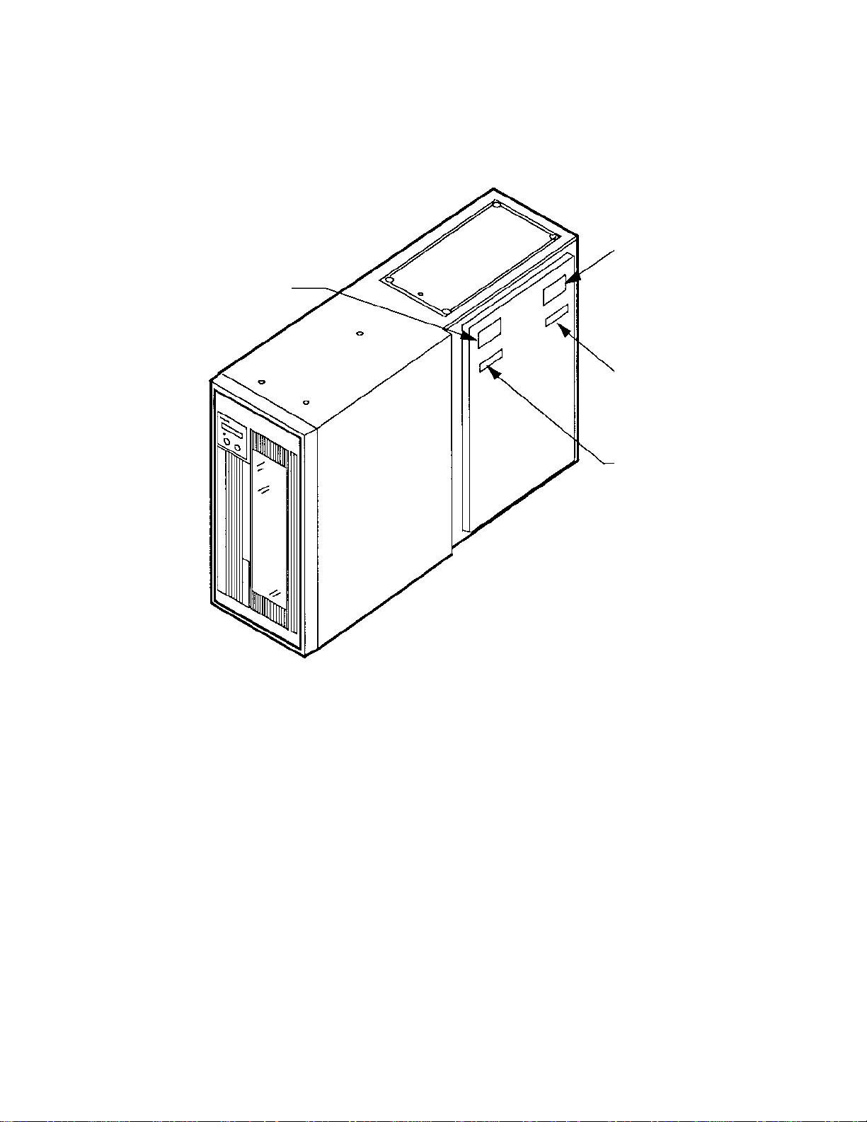
WARNING LABELS
The LF 6600 is classified as a laser product and meets all United States federal requirements. The warning
labels shown in the figure below have been applied to the Drive to ensure compliance with federal
regulations and must not be removed from the LF 6600.
LASER CLASS
LABEL
LASER DANGER
LABEL
CANADIAN
CLASS A LABEL
FCC, RFI,
CLASS A LABEL
Location of LF 6600 Warning Labels
EP006043
97653976 F
Page 21

PLASMON LASER MAGNETIC STORAGE - LF 6600 User Manual
Page 22

UNPACKING AND REPACKING
INSTRUCTIONS
The LF 6600 is shipped with foam packing material which protects the unit from shock and vibration. When
you receive your LF 6600, inspect the shipping carton for damage before unpacking the unit to
substantiate a claim with the carrier if the unit is damaged. Retain all original packing materials for
possible reshipment.
WARNING
The LF 6600 must be unpacked, repacked and transported by two
persons. Physical injury can result if one person attempts to lift the LF
6600. A wheeled cartis recommended for transporting the LF 6600
within a building. Precautions should be taken to guard against
sudden bumps and jarring.
UNPACKING THE TOWER CONFIGURATION
The LF 6600 is packaged as illustrated in the next figure. The top, bottom and sides of the LF 6600 are
protected from shock and vibration by foam cushions. The top cushions are also used to hold the
accessories box (inner box) which is placed between the blocks of foam.
To unpack the unit:
1) Move the carton to the installation site. Unpacking the carton at the installation site
minimizes the effects of vibration and shock.
2) Cut the tape and straps that secure the top of the box. Do not allow the cutting blade to
penetrate into the carton.
3) Carefully lift the outer corrugated carton up and remove it while supporting the inner
hinged wooden ramp. When the carton is removed, lower the ramp to the floor and
remove the front foam cushion.
4) Remove the accessories box (inner carton) containing cables and documentation and the
two foam cushions which support the box. Remove the ESD protective packing
material.
97653976 F
Page 23
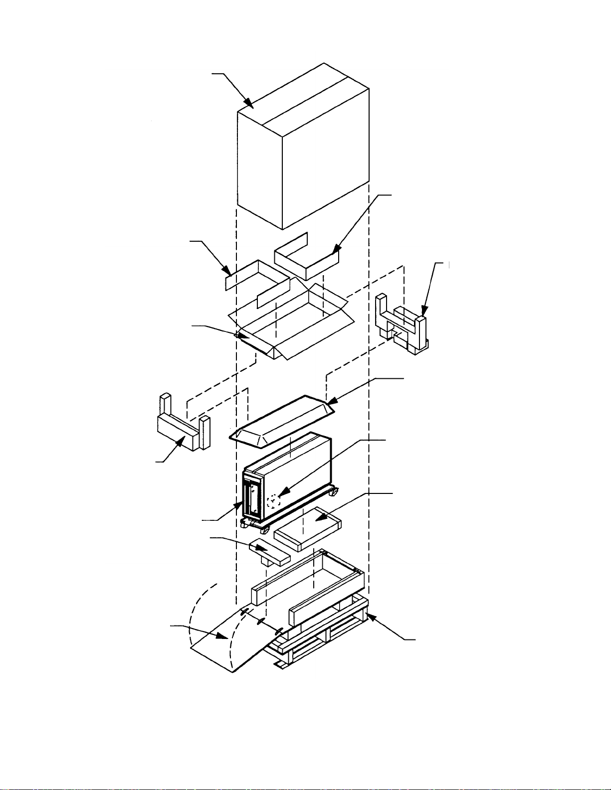
OUTER CARTON
INSERT
INNER CARTON
INSERT
REAR FOAM
CUSHION
FRONT
FOAM CUSHION
LF6600
PALLET CUSHION
HINGED
RAMP
ESD PROTECTIVE
PACKING MATERIAL
FOAM INSERT LOCATED
BETWEEN SHUTTLE AND
FRAME OF THE DRIVE
CASTER SUPPORT
PALLET
LF 6600 Tower Packing
PLASMON LASER MAGNETIC STORAGE - LF 6600 User Manual
Page 24
EP004566
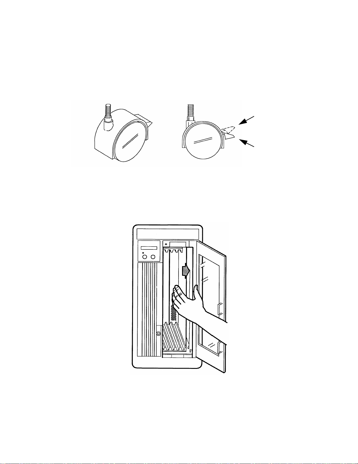
5) Ensure that the casters are locked. Lift the front end of the LF 6600 high enough to remove
the pallet cushion and then lower the LF 6600 onto its casters.
6) Unlock the casters and roll the LF 6600 down the ramp to its installation location.
Precautions should be taken to avoid sudden bumps and jarring.
7) Lock the casters once you have the LF 6600 situated at its installation location.
UNLOCKED
LOCKED
Caster for the LF 6600 Tower
8) Open the media access door and remove the foam insert. Manually move shuttle all the
way to the right to the home position.
Moving the Shuttle to the Home Position
97653976 F
Page 25
UNPACKING THE RACK MOUNT CONFIGURATION
To unpack the LF 6600 Rack Mount configuration, refer to the next figure and perform the following
procedure:
1) Move the carton to the installation site. Unpacking the carton at the installation site
minimizes the effects of vibration and shock.
2) Cut the tape that secures the top of the box. Do not allow the cutting blade to penetrate
into the carton.
3) Carefully lift the outer corrugated carton up and remove it.
4) Remove the accessories box (inner carton) containing cables and documentation, and
remove the ESD protective packing material.
5) Remove the two cushions which support the accessories box (inner carton).
6) Carefully lift and remove the LF 6600 from the shipping carton and place it on a flat surface
capable of supporting 48 kg (106 lbs). A wheeled cart is recommended for transporting
the LF 6600 within a building. Precautions should be taken to avoid sudden bumps and
jarring.
CAUTION
The bezel is slightly larger than the chassis. When placing the drive
onto a flat surface, allow the front end of the LF 6600 to extend over
the edge of the supporting surface so that the bezel does not bear any
weight.
7) Open the media access door and remove the foam insert. Manually move the shuttle all
the way to the right to the home shuttle position.
PLASMON LASER MAGNETIC STORAGE - LF 6600 User Manual
Page 26
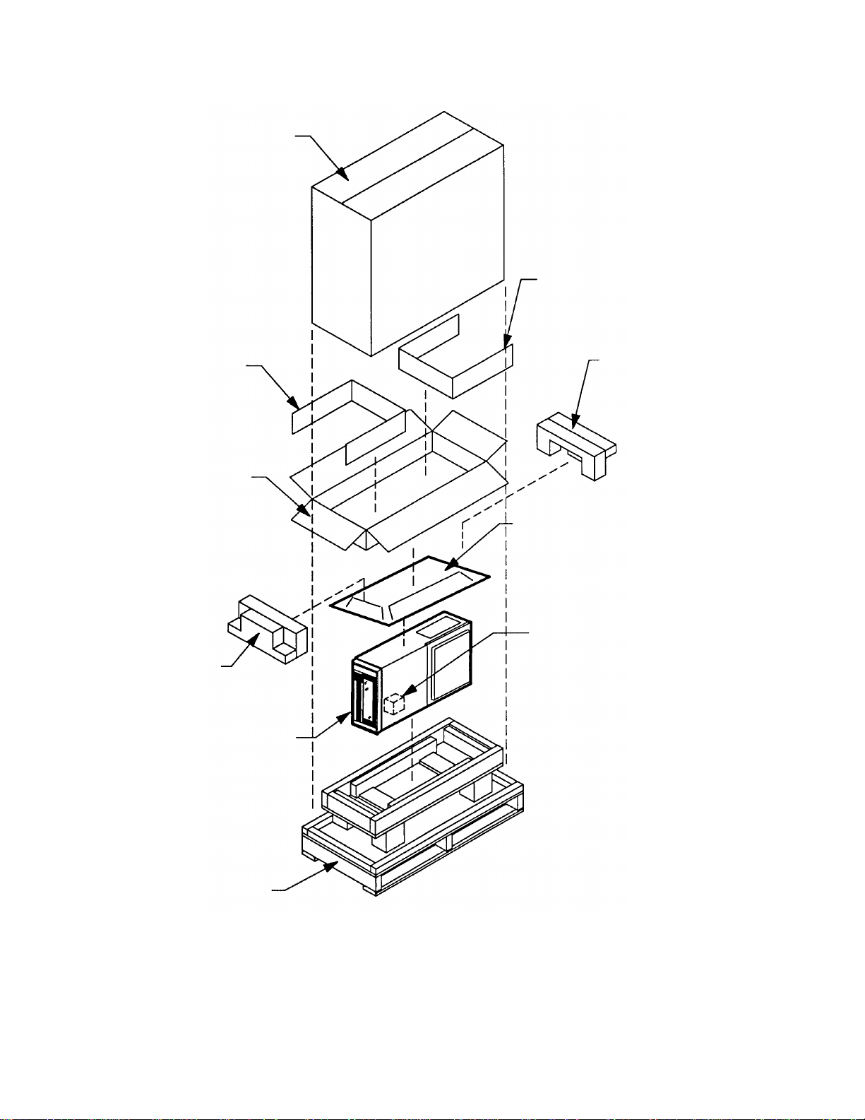
INSERT
INNER
CARTON
OUTER
CARTON
INSERT
REAR FOAM
CUSHION
ESD PROTECTIVE
PACKING MATERIAL
FRONT
FOAM
CUSHION
PALLET
FOAM INSERT LOCATED
BETWEEN SHUTTLE AND
DRIVE FRAME
LF 6600
LF 6600 Rack Mount Packing
97653976 F
Page 27

INSPECTING THE LF 6600
The following items should be included in the LF 6600 carton:
• one LF 6600 with Bezel assembly (Tower comes completely assembled)
• one AC power cable
• one User Manual
• one combination manual baseplate/door lock release tool
• I/O cables (optional)
• terminators (optional)
The following optional items, if ordered, will have been shipped with the LF 6600 in separate cartons:
• LM 6000 Media Cartridges
• Rack Mount Installation Kit
• Blank Panel Kit
After unpacking the LF 6600, check for:
• damage to the chassis cover, chassis and bezel
• damage to connectors
• dislocated or broken controls and indicators
Report all discrepancies, missing items and damaged equipment to your supplier.
If condensation exists on the drive, allow the moisture to evaporate by exposing the LF 6600 to the
operating environment for at least 6 hours before powering on the unit.
REPACKING THE LF 6600
The LF 6600 should be repacked using the original packing materials. Prior to packaging the LF 6600,
close the baseplates as described in the next section. Repack the LF 6600 using the following procedure.
CAUTION
Shipping the LF 6600 without closing the baseplates may result in
damage to the drive which is not covered under warranty.
PLASMON LASER MAGNETIC STORAGE - LF 6600 User Manual
Page 28
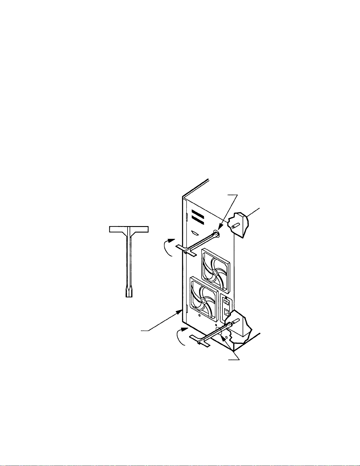
CLOSING THE BASEPLATES
1) Ensure that a cartridge is not inserted in the drive; if it is, unload the cartridge. Remove all
cartridges from the shuttle. To remove cartridges from a drive that is not operational,
follow the procedure below:
a.) Ensure that the AC Power switch is set to the OFF ( O ) position.
b.) At the rear panel, insert the manual release tool into the upper access hole
and engage the recessed D-shaped shaft. Turn the tool handle clockwise as far
as it will turn, closing the upper baseplate.
c.) Repeat step b) at the lower manual release access hole to close the lower
baseplate.
2) Select the "Park Drive" option, as explained in the Operating Instruction section of this
manual.
UPPER
ACCESS
HOLE
MANUAL RELEASE
TOOL
REAR PANEL
Manually Closing the Drive's Baseplates
LOWER ACCESS
HOLE
EP006047
97653976 F
Page 29

REPACKING THE TOWER CONFIGURATION
1) Open the media access door.
2) Manually push the shuttle all the way to the left and insert the foam shipping block to hold
it in place. Close the media access door.
3) Roll the LF 6600 up onto its shipping pallet and lock all four casters to prevent rolling.
4) Lift the front and rear of the LF 6600 high enough and place the caster support underneath
the drive.
5) Raise the wooden ramp to the vertical position and place the pallet cushion between the
ramp and the front panel of the LF 6600. Place the ESD protective packing material on
top of the drive.
6) Place the two end cushions which hold the accessories box on the top front and rear of the
LF 6600.
7) Place the power and interface cables, User Manual and other accessories into the options
and accessories box and seal with tape. Place this box between the top end cushions.
8) Slip the corrugated shipping carton over the LF 6600 and the raised ramp, and lower the
carton down to the top of the pallet.
9) Strap the carton to the pallet at each end.
PLASMON LASER MAGNETIC STORAGE - LF 6600 User Manual
Page 30
 Loading...