

PlasmaWALL XP-65DHD, XP-65DHDxa User Guide
OWNER’S OPERATING MANUAL
XP-65DHD
TM
XP-65DHDxa
High Definition, 1080p Flat Panel Plasma Display
with
and
Digital High Definition
with Vivix II
TM
Technology
TM
Controller


TWO YEAR LIMITED WARRANTY
For Plasma Displays
Congratulations on your purchase of a Runco video product and welcome to the Runco family! We believe Runco produces
“The World’s Finest Home Theater Products.” With proper installation, setup and care, you should enjoy many years of
unparalleled video performance.
This is a LIMITED WARRANTY as defined in the Magnuson-Moss Warranty Act. Please read it carefully and retain it with your
other important documents.
WHAT IS COVERED UNDER THE TERMS OF THIS LIMITED WARRANTY:
SERVICE LABOR: Runco will pay for service labor by a Runco Authorized Service Center when needed as a result of a
manufacturing defect for a period of three (3) years from the effective date of delivery to the end user (excluding the plasma
glass panel).
PARTS (not including plasma glass panel): Runco will provide new or rebuilt replacement parts for the parts that fail due to
defects in materials or workmanship for a period of three (3) years from the effective date of delivery to the end user. Such
replacement parts are then subsequently warranted for the remaining portion (if any) of the original warranty period.
PLASMA GLASS PANEL: Runco will pay for service labor by a Runco Authorized Service Center when needed as a result of a
manufacturing defect for a period of one (1) year from the effective date of delivery to the end user. In addition, Runco will
provide new or rebuilt replacement parts for the parts that fail due to defects in materials or workmanship for a period of one (1)
year from the effective date of delivery to the end user. Such replacement parts are then subsequently warranted for the
remaining portion (if any) of the original warranty period.
Y
IMINAR
WHAT IS NOT COVERED UNDER THE TERMS OF THIS LIMITED WARRANTY:
Image burn-in on plasma display panels is specifically excluded from coverage under this Limited Warranty. Image burn-in is
the result of misuse of the product and therefore cannot be repaired under the terms of this Limited Warranty.
Normal viewing material such as television/satellite broadcasts, videotape or DVDs (not put into pause for extended periods of
time) will not cause damage to your display under normal conditions. Many DVD players are also equipped with screen savers
for this reason.
L
PRE
TO AVOID IMAGE RETENTION (Burn-in): Please ensure that still images are left on your plasma display panel for no more
than a few minutes. Also ensure that images displayed in the 4:3 aspect ratio mode (black or gray stripes, but no picture
information is present on the left and right edges of the screen) are used as infrequently as possible. This will prevent
permanent image burns on your plasma display panel, which can be seen permanently under certain conditions once burn-in
has occurred.
The types of images to avoid include video games, still images and computer screens with stationary tool bars and icons. (This
is why computers are equipped with screen savers – to prevent still images from burning into the monitor’s phosphors after
being displayed continuously for an extended period of time).
This Limited Warranty only covers failure due to defects in materials and workmanship that occur during normal use and does
not cover normal maintenance. This Limited Warranty does not cover cabinets or any appearance items; failure resulting from
accident, misuse, abuse, neglect, mishandling, misapplication, faulty or improper installation or setup adjustments; improper
maintenance, alteration, improper use of any input signal; damage due to lightning or power line surges, spikes and
brownouts; damage that occurs during shipping or transit; or damage that is attributed to acts of God. In the case of remote
control units, damage resulting from leaking, old, damaged or improper batteries is also excluded from coverage under this
Limited Warranty.
CAUTION: THIS LIMITED WARRANTY ONLY COVERS RUNCO PRODUCTS PURCHASED FROM RUNCO AUTHORIZED
DEALERS. ALL OTHER PRODUCTS ARE SPECIFICALLY EXCLUDED FROM COVERAGE UNDER THIS WARRANTY.
PlasmaWall XP-65DHD Owner’s Operating Manual iii

MOREOVER, DAMAGE RESULTING DIRECTLY OR INDIRECTLY FROM IMPROPER INSTALLATION OR SETUP IS
SPECIFICALLY EXCLUDED FROM COVERAGE UNDER THIS LIMITED WARRANTY. IT IS IMPERATIVE THAT INSTALLATION
AND SETUP WORK BE PERFORMED ONLY BY AN AUTHORIZED RUNCO DEALER TO PROTECT YOUR RIGHTS UNDER
THIS WARRANTY. THIS WILL ALSO ENSURE THAT YOU ENJOY THE FINE PERFORMANCE OF WHICH YOUR RUNCO
PRODUCT IS CAPABLE WHEN INSTALLED AND CALIBRATED BY RUNCO AUTHORIZED PERSONNEL.
RIGHTS, LIMITS AND EXCLUSIONS:
Runco limits its obligations under any implied warranties under state laws to a period not to exceed the warranty period. There
are no express warranties. Runco also excludes any obligation on its part for incidental or consequential damages related to
the failure of this product to function properly. Some states do not allow limitations on how long an implied warranty lasts, and
some states do not allow the exclusion or limitation of incidental or consequential damages. So the above limitations or
exclusions may not apply to you. This warranty gives you specific legal rights, and you may also have other rights that vary from
state to state.
EFFECTIVE WARRANTY DATE:
This warranty begins on the effective date of delivery to the end user. For your convenience, keep the original bill of sale as
evidence of the purchase date.
IMPORTANT – WARRANTY REGISTRATION:
Y
Please fill out and mail your warranty registration card. It is imperative that Runco knows how to reach you promptly if we
should discover a safety problem or product update for which you must be notified.
CONTACT A RUNCO AUTHORIZED SERVICE CENTER TO OBTAIN SERVICE:
Repairs made under the terms of this Limited Warranty covering your Runco video product will be performed at the location of
the product, during usual working hours, providing location of product is within normal operating distance from a Runco
Authorized Service Center. In some instances it may be necessary for the product to be returned to the Runco factory for
repairs. If, solely in Runco’s judgment, location of product to be repaired is beyond normal operating distance of the closest
Runco Authorized Service Center, or the repair requires the unit be returned to the Runco factory, it is the owner’s
responsibility to arrange for shipment of the product for repair. These arrangements must be made through the selling Runco
Dealer. If this is not possible, contact Runco directly for a Return Authorization number and shipping instructions. Runco will
return product transportation prepaid in the United States, unless no product defect is discovered. In that instance, shipping
costs will be the responsibility of the owner.
COPYRIGHT AND TRADEMARKS:
© Copyright 2007 Runco International. This document contains proprietary information protected by copyright, trademark and
other intellectual property laws. All rights are reserved. No part of this manual may be reproduced by any mechanical,
electronic or other means, in any form, without prior written permission of the manufacturer.
Reflection, Enhanced GEN3, DHD, Vivix, Virtual Cinema, CineWide, AutoScope, O-Path, CinOptx, LiveLink, CSMS, SuperOnyx
and VirtualWide are trademarks of Runco International. All other trademarks and registered trademarks used in this document
are the property of their respective owners.
PRE
IMINAR
L
THX and the THX logo are trademarks of THX Ltd. which may be registered in some jurisdictions. All rights reserved.
Runco International products are manufactured under one or more of the following patents: US. Patent 6755540 and Other
Patents Pending.
iv PlasmaWall XP-65DHD Owner’s Operating Manual

ADDITIONAL INFORMATION:
To locate the name and address of the nearest Runco Authorized Service Center, or for additional information about this
Limited Warranty, please call or write:
RUNCO INTERNATIONAL, INC.
Attn: Customer Service Department
2900 Faber Street
Union City, CA 94587
Ph: (510) 324-7777
Y
Fax: (510) 324-9300
Toll Free: (800) 23-RUNCO
RUNCO VIDEO-PRODUCT INFORMATION
RETAIN THIS INFORMATION FOR YOUR RECORDS
IMINAR
_________________________________________________________ ________________________________________
L
Model Purchased Date
____________________________________________________________________________________________________________
Serial Number
____________________________________________________________________________________________________________
Runco Authorized Dealer Name
____________________________________________________________________________________________________________
PRE
Address
____________________________________________ __________________ ________________________
City State/Province Postal Code
____________________________________________ _________________________________________________________
Phone Fax
PlasmaWall XP-65DHD Owner’s Operating Manual v
Safety Precautions
Thank you for your purchase of this quality Runco product! It has been designed to provide you with the quality of video that is
expected in a home theater. This manual is your guide through the menus and operation. For the best performance, please
read it carefully and keep it handy for future reference.
WARNING
CAUTION
RISK OFELECTRIC SHOCK
DO NOTOPEN
TO REDUCE THE RISK OF ELECTRIC SHOCK
DO NOT REMOVE COVER (OR BACK)
NO USER SERVICEABLE PARTS INSIDE.
REFER SERVICING TO QUALIFIED
CAUTION
To turn off main power, be sure to remove the plugs from power outlets. The power outlet socket should be installed as near to
the equipment as possible, and should be easily accessible.
WARNING
TO PREVENT FIRE OR SHOCK HAZARDS, DO NOT EXPOSE THIS UNIT TO RAIN OR MOISTURE. ALSO DO NOT USE THIS
UNIT’S POLARIZED PLUG WITH AN EXTENSION CORD RECEPTACLE OR OTHER OUTLETS, UNLESS THE PRONGS CAN
BE FULLY INSERTED. REFRAIN FROM OPENING THE CABINET AS THERE ARE HIGH-VOLTAGE COMPONENTS INSIDE.
REFER SERVICING TO QUALIFIED SERVICE PERSONNEL.
CAUTION:
SERVICE PERSONNEL.
This symbol is intended to alert the user to the presence of uninsulated
“dangerous voltage” within the product’s enclosure that may be of sufficient
magnitude to constitute a risk of electric shock.
This symbol is intended to alert the user to the presence of important
operating and maintenance (servicing) instructions in the literature
accompanying the appliance.
Y
IMINAR
L
WARNING
This equipment generates, uses, and can radiate radio frequency energy and, if not installed and used in accordance with the
Installation Manual, may cause harmful interference to radio communications. Operation of this equipment in a residential area
may cause harmful interference, in which case the user will be required to correct the interference at his own expense.
Please read and follow the safety precautions listed below to ensure the equipment is free from damage, and to ensure that no
injury will occur as a result of improper use.
• Do not insert any object, especially metal or liquids, into the plasma display.
• Do not place any objects containing water or any other liquid on top of the plasma display.
• Do not place the units in direct sunlight, near heaters or in extremely dusty or humid locations.
• Do not install this system outdoors or otherwise exposed to the elements.
• Do not place heavy objects on top of the plasma display.
• If the power cord is damaged or frayed in any way, electrical shock and/or fire may result. Do not place objects on the
power cord, and keep the cord away from heat-emitting devices. Should the power cord become damaged in any way,
please contact your Runco Dealer for a replacement cord.
• Do not remove the cover of the plasma display for any reason. If any problems arise with the unit, please contact a Runco
Dealer or Runco International for service. Removing the covers will void the warranty.
PRE
vi PlasmaWall XP-65DHD Owner’s Operating Manual

1Table of Contents
TWO YEAR LIMITED WARRANTY ................................................................................. iii
Safety Precautions ......................................................................................................... vi
1. Introduction ............................................................................................................... 1
About This Manual ....................................................................................................... 1
Target Audience ..................................................................................................... 1
If You Have Comments About This Manual... ..........................................................1
Textual and Graphic Conventions ...........................................................................1
Using This Manual ........................................................................................................ 2
Description, Features and Benefits ...............................................................................3
Key Features and Benefits ...................................................................................... 3
Parts List ...............................................................................................................4
2. Controls and Functions ............................................................................................5
PlasmaWall at a Glance ................................................................................................ 5
Controls and Indicators ...........................................................................................5
Connectors ............................................................................................................6
DHD Controller Front Panel ..........................................................................................7
DHD Controller Rear Panel ........................................................................................... 8
Outputs .................................................................................................................. 8
Inputs .....................................................................................................................8
DHD Controller Remote Control ................................................................................. 10
PRE
3. Installation ...............................................................................................................13
Remote Control ..........................................................................................................13
IMINAR
L
Y
Notes on Batteries ................................................................................................ 13
Notes on Remote Control Operation .....................................................................13
Quick Setup ............................................................................................................... 15
Installation Considerations ..........................................................................................16
High-Altitude Operation ........................................................................................ 16
Mounting the PlasmaWall on a Wall or Table Stand ..............................................16
Ambient Light .......................................................................................................17
Ventilation ............................................................................................................. 17
Other Considerations ............................................................................................ 18
PlasmaWall XP-65DHD Owner’s Operating Manual vii

Table of Contents
Connections to the PlasmaWall and DHD Controller ................................................... 19
Connecting the PlasmaWall to the DHD Controller ................................................ 19
Connecting Source Components to the DHD Controller ....................................... 21
RS-232 Controller Connection .............................................................................. 25
Connecting 12-Volt Trigger Outputs to External Equipment .................................. 25
Connecting an External IR Receiver to the DHD Controller .................................... 26
4. Operation ................................................................................................................. 27
Turning on the Power ................................................................................................. 27
Setting the Computer Display Properties .................................................................... 28
Using the DHD Controller Menus ................................................................................29
Main Menu ...........................................................................................................31
Input Source ........................................................................................................ 31
Aspect Ratio ........................................................................................................ 31
Picture .................................................................................................................33
Input Position........................................................................................................ 36
ISF Presets ........................................................................................................... 37
Information ........................................................................................................... 37
Calibration ............................................................................................................38
Service ................................................................................................................. 40
5. Maintenance and Troubleshooting ........................................................................ 45
Cleaning .....................................................................................................................45
Cleaning the Display Panel Body and Remote Control ..........................................45
Cleaning the Screen.............................................................................................. 45
Cleaning the Vents................................................................................................ 45
IMINAR
L
Y
PRE
Troubleshooting Tips ..................................................................................................46
6. Serial Communications ..........................................................................................49
RS-232 Connection and Port Configuration ...............................................................49
Serial Command Syntax ............................................................................................. 49
7. Specifications .......................................................................................................... 55
PlasmaWall Specifications .......................................................................................... 55
DHD Controller Specifications .................................................................................... 56
PlasmaWall Dimensions ............................................................................................. 57
viii PlasmaWall XP-65DHD Owner’s Operating Manual

1List of Figures
2-1. PlasmaWall Front-Panel Controls and Indicators........................................................... 5
2-2. PlasmaWall Rear Panel................................................................................................. 6
2-3. DHD Controller Front Panel ..........................................................................................7
2-4. DHD Controller Rear Panel ........................................................................................... 8
2-5. DHD Controller Remote Control ................................................................................. 10
3-1. Available Range of the Remote Control ...................................................................... 13
3-2. Ventilation Requirements for Enclosure Mounting ....................................................... 17
3-3. Connecting the PlasmaWall to the DHD Controller .....................................................19
3-4. RS-232 Connection from the DHD Controller to the PlasmaWall ................................20
3-5. HDMI Source Connections .........................................................................................21
3-6. Digital (DTV) RGB Connections...................................................................................22
3-7. Analog RGB Connections...........................................................................................23
3-8. Composite, S-Video and Component Video Connections........................................... 24
3-9. RS-232 Control System Connection........................................................................... 25
3-10. Connecting 12-Volt Trigger Outputs ......................................................................... 25
3-11. External IR Receiver Connection............................................................................... 26
4-1. DHD Controller OSD Menu Structure for PlasmaWall.................................................. 30
4-2. Typical PLUGE Pattern for Adjusting Brightness .........................................................33
4-3. Typical Gray Bar Pattern for Adjusting Contrast .......................................................... 34
4-4. Typical Color Bar Pattern for Adjusting Color Saturation and Tint................................35
PRE
4-5. Typical Test Pattern for Adjusting Sharpness..............................................................36
7-1. PlasmaWall Model XP-65DHD Dimensions (with Optional Table Stand) ......................57
IMINAR
L
Y
PlasmaWall XP-65DHD Owner’s Operating Manual ix

List of Figures
Notes:
Y
IMINAR
L
PRE
x PlasmaWall XP-65DHD Owner’s Operating Manual

1. Introduction
This Owner’s Manual describes how to install, set up and operate the Runco PlasmaWall
Flat-Panel Plasma Display Monitor and DHD Controller (Model XP-65DHD or
XP-65DHDxa).
Throughout this manual, the Runco PlasmaWall Flat-Panel Plasma Display Monitor and
DHD Controller are referred to collectively as the “PlasmaWall.” Except where otherwise
indicated, the information in this manual applies to both PlasmaWall models.
Y
most out of the PlasmaWall.
Runco has made every effort to ensure that this manual is accurate as of the date it was
printed. However, because of ongoing product improvements and customer feedback, it
may require updating from time to time. You can always find the latest version of this and
other Runco product manuals on-line, at www.runco.com.
Runco welcomes your comments about this manual. Send them to techpub@runco.com.
Text Conventions: The following conventions are used in this manual, in order to clarify
the information and instructions provided:
• Remote control button identifiers are set in upper-case bold type; for example, “Press
EXIT to return to the previous menu.”
• Computer input (commands you type) and output (responses that appear on-screen) is
shown in monospace (fixed-width) type; for example: “To change the aspect ratio to
Letterbox, type LETTERBOX <Enter>.”
• All keys with functional names are initial-capped, set in bold type and enclosed in angle
brackets. These keys are the following: <Enter>, <Spacebar>, <Control>, <Esc>
and <Tab>.
• <Enter> indicates that you may press either the RETURN or ENTER key on your
computer keyboard if it has both keys.
PRE
IMINAR
L
1.1 About This Manual
Target AudienceRunco has prepared this manual to help home theater installers and end users get the
If You Have Comments About This Manual...
Textual and Graphic Conventions
In addition to these conventions, underlining, boldface and/or italics are occasionally used
to highlight important information, as in this example:
Note
PlasmaWall XP-65DHD Owner’s Operating Manual 1
A carriage return must be used after each command or string.
Introduction
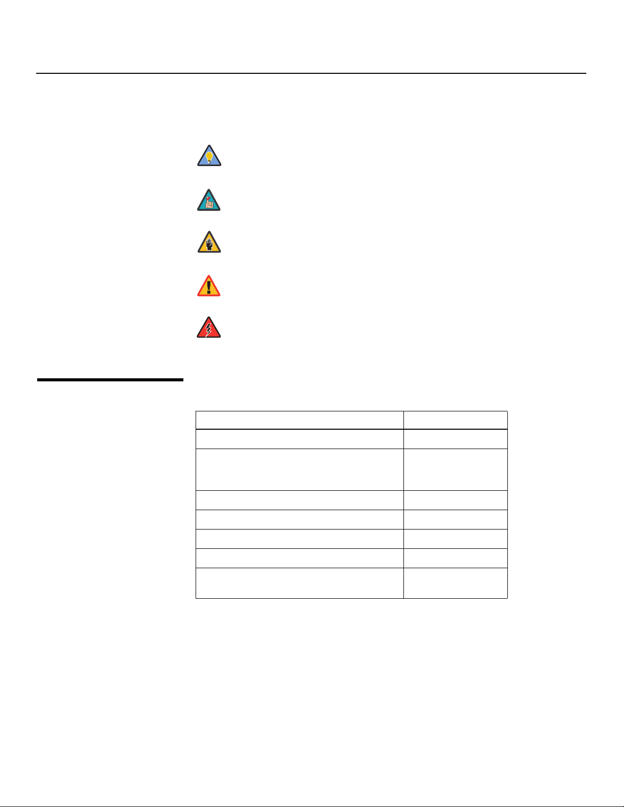
Graphic Conventions: These symbols appear in numerous places throughout the
manual, to emphasize points that you must keep in mind to avoid problems with your
equipment or injury:
1.2
Using This Manual
Tip
Note
Caution
TIPS highlight time-saving short cuts and helpful guidelines for using
certain features.
NOTES emphasize text with unusual importance or special
significance. They also provide supplemental information.
CAUTIONS alert users that a given action or omitted action can
degrade performance or cause a malfunction.
Y
WARNING
DANGER!
Use the following table to locate the specific information you need in this manual.
WARNINGS appear when a given action or omitted action can result
in damage to the equipment, or possible non-fatal injury to the user.
DANGER appears when a given action can cause severe injury or
death.
IMINAR
If you need... ... Turn to page:
Information about obtaining service iv
L
General information about the PlasmaWall
Flat-Panel Plasma Display Monitor and DHD Controller
Installation instructions 13
PRE
First-time configuration instructions 27
Advanced configuration instructions 38
Troubleshooting tips 46
Specifications for the PlasmaWall Flat-Panel
Plasma Display Monitor and DHD Controller
3
55
2 PlasmaWall XP-65DHD Owner’s Operating Manual

Introduction
The new Runco XP-65DHD plasma monitor establishes a higher threshold for flat panel
display products. This is our largest and highest-resolution plasma ever, at 65 inches
diagonal and 1920 x 1080 (1080p) native resolution.
In addition, the XP-65DHD takes picture quality to a whole new level boasting our
brightest picture, best contrast ratio, deepest black levels and most spot-on high
definition colorimetry ever! In addition, sophisticated 16-bit digital video processing, a new
milestone, results in 4096 steps of graduation for seamless images completely devoid of
the primitive "solarization" and "stair stepping" characteristics previously plaguing digital
flat panel displays.
The XP-65DHD features all of the Runco technologies you have come to expect from the
World's Finest Home Theater Products. Discrete multiple aspect ratio control includes
VirtualWide™ for viewing 4:3 content in widescreen without appreciable picture
degradation, as well as ISF(ccc) calibration modes to easily maintain ISF standards. The
automation interface includes RS-232 control with discrete aspect ratio, input and power
on/off selection.
The included DHD with HDMI Digital Video Controller/Processor provides a pure digital
signal path from input to output as well as a broad array of video input choices, all
available from its position in the equipment rack, with only digital video and command
cables running to the display itself.
Finally, the XP-65DHD not only represents a leap forward in high definition flat-panel
technology, but our engineering advances in plasma design ensure that it will enjoy a long
life in any installation, with operation extending to as much as 60,000 hours. At less than
4-1/2 inches thin, the XP-65DHD provides unlimited installation flexibility as well.
IMINAR
Y
1.3 Description, Features and Benefits
For high-altitude installations, Runco also offers the XP-65DHDxa with industry-leading
high-altitude compliance to over 9000 feet mean sea level (MSL). The XP-65DHDxa
shares all other features and specifications with the XP-65DHD.
• 16:9 Native Resolution: 1920 x 1080
• Multiple Aspect Ratios with VirtualWide™ Mode
• Includes the new DHD with HDMI video controller/processor
• 65-inch diagonal image area
• Only 4-1/2 inches thin
• Model XP-65DHDxa is high-altitude compliant to 9000 feet
• Exceptional detail and artifact-free video enhancement
• Vivix™ video processing with 3:2 film detection circuitry
PRE
L
Key Features and BenefitsThe PlasmaWall offers these key features and benefits:
PlasmaWall XP-65DHD Owner’s Operating Manual 3

Introduction
Parts List Your PlasmaWall is shipped with the following items. If any items are missing or damaged,
➤
please contact your Runco dealer or Runco Customer Service at (800) 23-RUNCO.
• PlasmaWall Flat-Panel Plasma Display Monitor and DHD Controller
• AC Power Cords (2)
• Remote Control Unit and two (2), AAA-size batteries
• RJ-11 Telephone Cable, 50 feet (15.24 meters)
• Serial Port Adapter, RJ-11 Female to DB-9 Female
• Rack-mount hardware for the DHD Controller
• Cable Ties (2)
• Warranty information and registration card
• PlasmaWall XP-65DHD Owner’s Operating Manual (this document)
Y
Optional Accessories:
• Wall Mount Kit (Runco part number RUHK-005075)
• Table Stand (Runco part number RUHK-005100)
IMINAR
L
PRE
4 PlasmaWall XP-65DHD Owner’s Operating Manual
2 4
3
2. Controls and Functions
2.1 PlasmaWall at a Glance
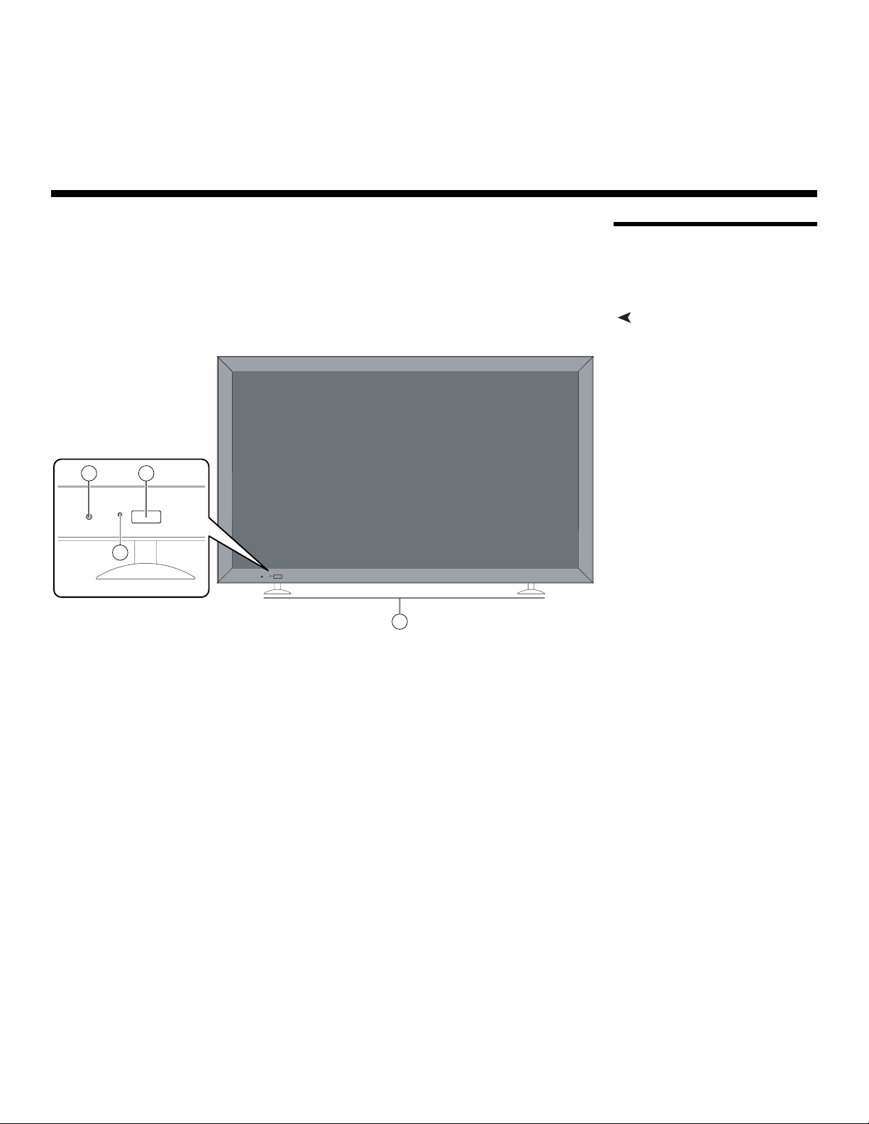
Controls and IndicatorsFigure 2-1 shows the PlasmaWall front-panel controls and indicators.
Y
IMINAR
L
1
Figure 2-1. PlasmaWall Front-Panel Controls and Indicators
1. DISPLAY STAN D
Optional accessory for table-top installations.
2. POWER BUTTON
Connects or disconnects the display panel from the AC power source.
3. STANDBY/ON INDICATOR
- Lights green to indicate normal operation;
- Lights red to indicate that the PlasmaWall is in standby mode.
4. REMOTE CONTROL SENSOR
Receives the signals from the remote control.
PRE
PlasmaWall XP-65DHD Owner’s Operating Manual 5
Controls and Functions
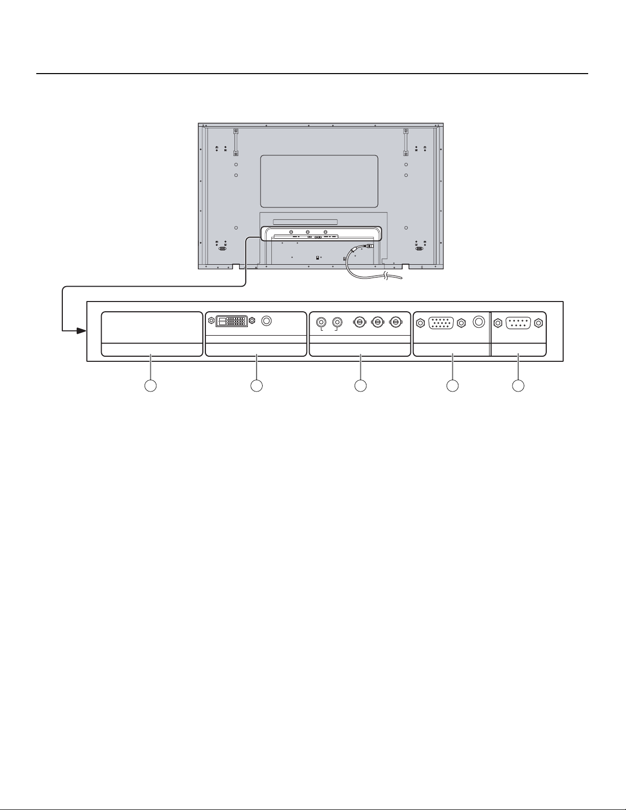
Connectors Figure 2-2 shows the rear-panel connector locations on the PlasmaWall.
➤
Y
AUDIO
AUDIO
DVI-D IN
SLOT1 SLOT3
1 2 3 4 5
SLOT2
RL
PR/CR/R PB/CB/B
COMPONENT/RGB IN
Y/G
AUDIO
SERIALPC IN
Figure 2-2. PlasmaWall Rear Panel
1. SLOT 1
Not used.
2. SLOT 2 (DVI-D input)
HDCP-compliant digital video input. Connect the HDMI output from the DHD
Controller to this input. (The audio input is not used. Connect the audio outputs
from your sources to an external audio receiver.)
PRE
3. SLOT 3
Not used.
4. PC IN
Not used.
5. RS-232C (9-pin, male D-Sub)
Connect the RS-232 OUT port on the DHD Controller to this input.
IMINAR
L
6 PlasmaWall XP-65DHD Owner’s Operating Manual
Controls and Functions
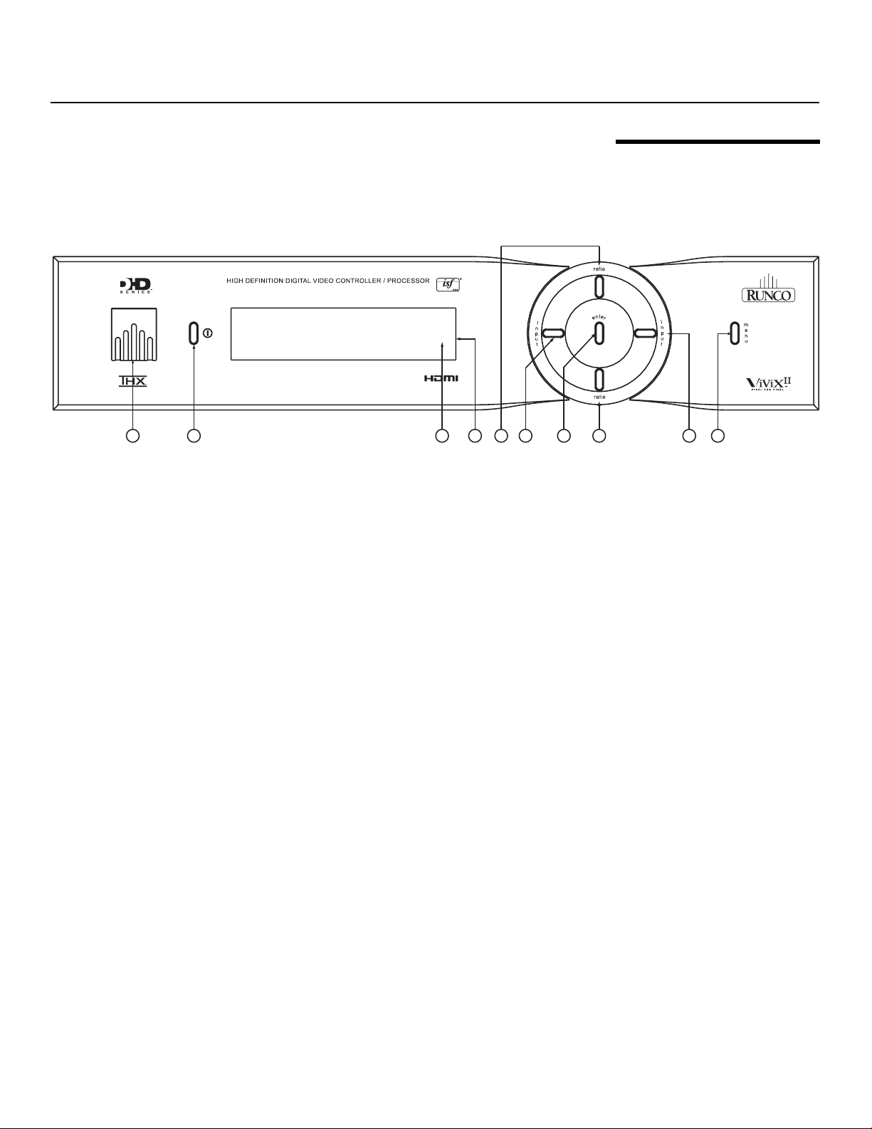
Figure 2-3 shows the controls and indicators on the DHD Controller front panel; the
paragraphs that follow describe them.
1
Figure 2-3. DHD Controller Front Panel
1. RUNCO ICON
Lights red to indicate that the DHD Controller is in standby mode; lights blue to
indicate that the unit is on.
2. POWER BUTTON
Press once to toggle from standby mode to on mode. Press it again to return to
standby mode. For a discrete on or off command, you can use the direct access
buttons on the remote control.
2
IMINAR
L
3
45
6
Y
7
2.2 DHD Controller Front Panel
8
9
10
3. IR SENSOR
Receives IR commands from the remote.
4. VACUUM FLUORESCENT DISPLAY
Can be used instead of the On-Screen Display (OSD). Displays currently-selected
menu or – if no menu is selected – the current source, signal format (NTSC or PAL)
and aspect ratio.
5. UP BUTTON
Used to direct select aspect ratios or move the menu cursor up in the OSD. When no
menu is present on-screen, the UP button toggles through aspect ratios in the
following order:
16:9 - 4:3 - Letterbox - VirtualWide - Cinema
6. LEFT BUTTON
Used to direct select inputs or move the menu cursor left in the On-Screen Display.
When no menu is present on-screen, the LEFT button toggles through the different
sources, in this order:
HDMI 2 - HDMI 1 - HD/RGB 2 - HD/RGB1 - Component SD - S-Video 2 - S-Video 1
- Composite
7. ENTER BUTTON
Press ENTER to select a highlighted menu item.
PRE
PlasmaWall XP-65DHD Owner’s Operating Manual 7
Controls and Functions
8. DOWN BUTTON
Used to direct select aspect ratios or move the menu cursor down in the OSD. When
no menu is present on-screen, this button toggles through the different aspect ratios,
in this order:
Cinema - VirtualWide - Letterbox - 4:3 - 16:9
9. RIGHT BUTTON
Used to direct select inputs or move the menu cursor right in the OSD. When no
menu is present on-screen, the RIGHT button toggles through the different sources,
in this order:
Composite - S-Video 1 - S-Video 2 - Component SD - HD/RGB 1 - HD/RGB 2 HDMI
1 - HDMI 2
2.3
DHD Controller Rear Panel
Serial No
Model
Video Processor / Controller
PRE
Note
buttons is available only on the analog inputs (HD/RGB, SD
Y
Component, Composite and S-Video).
10. MENU BUTTON
Press this button to access the OSD controls, or to exit the current menu and return
to the previous one.
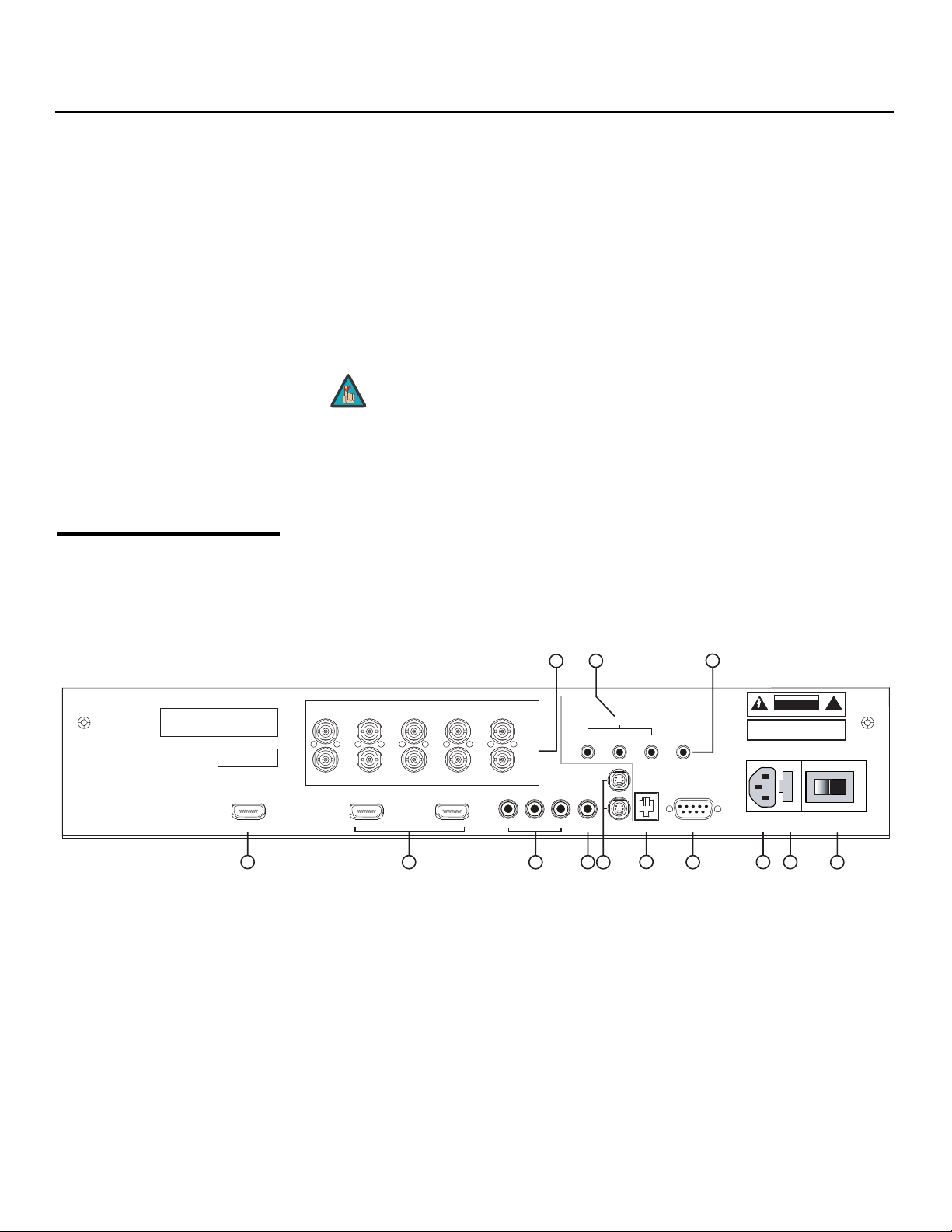
Figure 2-4 shows the rear connector panel on the DHD Controller.
IMINAR
79
The “direct select” function of the UP, DOWN, LEFT and RIGHT
HD1
HD2
Component Video
3
SYSTEM CONTROL INTERFACE
TRIGGERS
2
1
S-Video 1
Video
S-Video 2
RS-232 Out
IR
3
WARNING:
TO REDUCE THE RISK OF FIRE
OR ELECTRIC SHOCK, DO NOT EXPOSE
THIS APPLIANCE TO RAIN OR MOISTURE.
RS-232 Control
CAUTION
RISK OF ELECTRIC SHOCK
DO NOT OPEN
AVIS: RISQUE DE CHOC ELECTRIQUE-NE PAS OUVRIR
CAUTION:
TO REDUCE THE RISK OF ELECTRIC
SHOCK, DO NOT REMOVE COVER. NO USERSERVICEABLE PARTS INSIDE. REFER SERVICING
TO QUALIFIED SERVICE CENTER.
100-230VAC 50-60 Hz, 165 Watts Max
Made In USA
L
R/Pr G/Y B/Pb
R/Pr G/Y B/Pb H V
INPUTS
HDMI 1 HDMI 2HDMI Out
HV
Pb Pr Y
!
1
Figure 2-4. DHD Controller Rear Panel
Outputs 1. HDMI OUT
Inputs 2. HDMI 1 / HDMI 2 (Digital)
➤
➤
3. HD1 / HD2 (5 x Analog BNCs)
10
2
4
5
8
6
11
12 13
Connect this to the SLOT 2 (DVI-D) input on the PlasmaWall (see Figure 2-2).
Two, HDCP-compliant digital video inputs for connecting a DVD player or HD tuner
with a DVI or HDMI output.
Two inputs (five BNCs per input) for connecting either RGB or component
high-definition television signals. The DHD Controller automatically detects the signal
format: RGB(HV) or YPrPb, 480p, 720p, 480i, 576i or 1080i.
8 PlasmaWall XP-65DHD Owner’s Operating Manual

4. COMPONENT VIDEO (RCA connectors)
Standard Definition (480i/576i) Component (YPrPb) input. This is the input for
component video from sources such as DVD players.
Controls and Functions
Tip
5. COMPOSITE VIDEO INPUT
Standard composite video input for connecting a VCR, laser disc player or other
composite video source.
6. S-VIDEO 1 / S-VIDEO 2
Two, standard S-Video inputs for connecting a DVD player, satellite receiver or Super
VHS (S-VHS) VCR.
7. 12-VOLT (750 mA) TRIGGER OUTPUTS
Connection for up to three (3), 12-volt trigger-controlled devices such as retractable
screens or screen masks.
8. ComLink (RS-232) OUTPUT
Connect this to the ComLink (RS-232) input on the projector, using the provided
communication cable.
9. IR
Wired input from a wired remote control or infrared receiver. It is a 3.5-mm, mini
phono jack, wired as follows:
Ring = +5V
Tip = IR Input
Sleeve = Ground
For best results, do not run your DVD player in progressive mode.
IMINAR
L
Note
When an external remote control or infrared receiver is connected
to the wired IR input, the IR sensor on the front of the DHD is
disabled.
Y
10. RS-232 CONTROL PORT
A female, 9-pin D-sub connector for interfacing with a PC or home theater
automation/control system.
11. POWER INPUT (100 to 240 VAC)
Connect the DHD Controller to power here.
12. MAIN AC FUSE
This is the main AC input fuse (5mm x 20mm, 500 mA, 250V slow-blow).
13. MAIN POWER SWITCH
Disconnects or applies power to the DHD Controller.
PlasmaWall XP-65DHD Owner’s Operating Manual 9
PRE
Controls and Functions
2.4 DHD Controller Remote Control
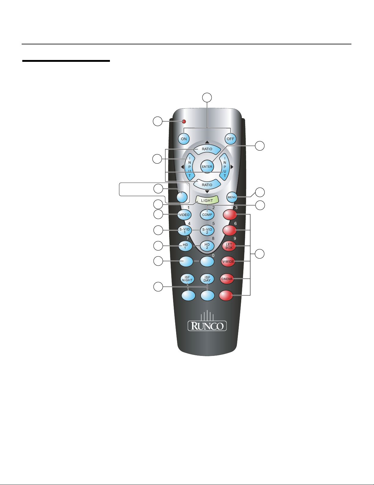
Figure 2-5 shows the DHD Controller remote control, and the paragraphs that follow
describe its functionality.
2
1
3
Y
7
9
10
(not available on
some models)
L
4
5
6
8
11
IMINAR
12
13
RETURN
EXIT
HDMI
16 : 9
4 : 3
HDMI
1
2
14
PRE
Figure 2-5. DHD Controller Remote Control
CUST
10 PlasmaWall XP-65DHD Owner’s Operating Manual
CUST
1
SVC
2

1. IR OUTPUT INDICATOR
Lights when a button is pressed to indicate that an IR signal is being transmitted.
2. ON / OFF
Press to turn the PlasmaWall on or off.
3. ENTER
Press to select a highlighted menu item or confirm a changed setting.
4. Cursor Keys ( , , , )
Use these buttons to select items or settings, adjust settings or switch display
patterns.
When no menus are present on-screen, the UP and DOWN buttons toggle through
the available aspect ratios, in this order:
UP Button = 16:9 - 4:3 - Letterbox - VirtualWide - Cinema
DOWN Button = Cinema - VirtualWide - Letterbox - 4:3 - 16:9
Likewise, the LEFT and RIGHT buttons toggle through the different source inputs, in
this order:
LEFT Button = HDMI 2 - HDMI 1 - HD/RGB2 - HD/RGB 1 - Component SD - S-Video
2 - S-Video 1 - Composite
RIGHT Button = Composite - S-Video 1 - S-Video 2 - Component SD - HD/RGB 1 -
HD/RGB 2 - HDMI 1 - HDMI 2
5. RETURN / EXIT
Press this button to exit the current menu and return to the previous one.
Controls and Functions
Y
Note
6. LIGHT
Press to illuminate the buttons.
7. MENU
Press this button to show or hide the OSD controls.
8. VIDEO (1)
Press to select Composite video input as the source or to enter the numeric
character
9. COMP (Component) (2)
Press to select Component SD (480i/576i) video input as the source or to enter the
numeric character “2.”
“1.”
Not all remote control units have this button. If yours does not, use
the MENU button (see below) to exit the current menu.
PRE
IMINAR
L
PlasmaWall XP-65DHD Owner’s Operating Manual 11
 Loading...