

Page 1

DINGO PUP
Negative Ground
20A Max. Charge
20A Max. Load
Dingo Series Expansion Unit
User Guide
Read this before installing
Ver 1.6 230317
Page 2
Dingo Pup User Guide
2
Install your controller:
• Vertically, where air can circulate around it;
• In a dry environment out of direct sunlight;
• Away from flammable gases or liquids;
• Away from spiders, wasps or other insects
which might make nests in it.
Pup configuration:
Each Pup must have its own address.
Configure the
Pup address and system voltage before connecting
the Dingo accessory bus.
Page 3
3
Dingo Pup User Guide
Wiring Instructions 6
Connecting Pup to the Dingo 14
Using the Menus 8
Choosing your Settings 10
What is a Dingo Pup?
The Dingo Pup is used to expand the capacity of
the Dingo solar charge controller. Up to 9 pups can
be added to a system. Each Pup is controlled by the
Dingo. The Dingo manages the whole charge control
process and displays the total charge and Ah figures
for the system.
Page 4
Dingo Pup User Guide
4
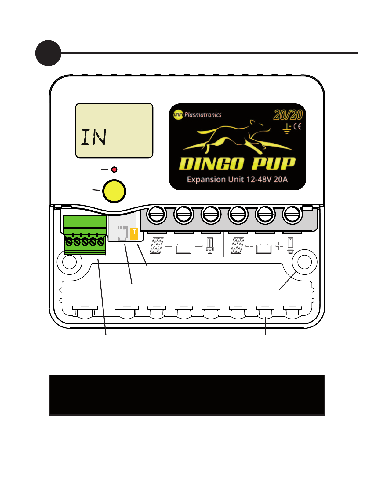
Screw wires into the high current terminals
tightly in the order listed on page 6.
Fig. 1
Warning: This controller is for DC current ONLY
638
BOOST
Di sp la y
Alarm LED
Terminals for G and sensor wires
(plug in termi nal block)
Accessory port
Mounting holes
Cable tie
posts
T
Test terminal
Ah
Button
See page 8
Page 5
5
Dingo Pup User Guide
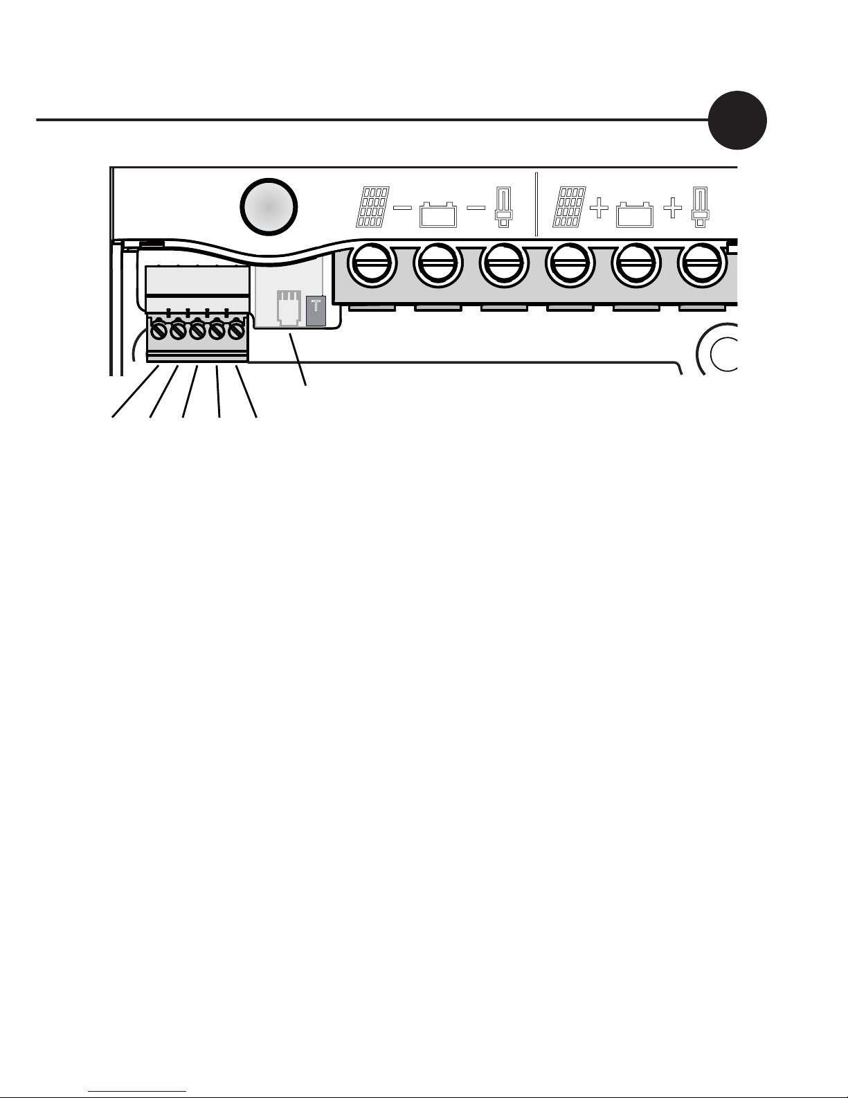
Basic Connection Order
1. Connect Battery
2. Test Solar Polarity
3. Connect Solar
4. Connect Load (if required)
5. Set Address and System Voltage
6. Connect the Pup to the Dingo Bus
T
BATTERY-
SOLAR+
BATTERY+
LOAD+
‘G’ Terminals
Sensor T+
Temperature T-
B+ Sense
LOAD-
SOLAR-
‘G’ Terminals
Accessory Port
Test terminal
Fig. 2
Page 6
Dingo Pup User Guide
6
Wiring instructions
For safety and to avoid damage, connection of wires must be
done in the following order.
All connections must be tight!
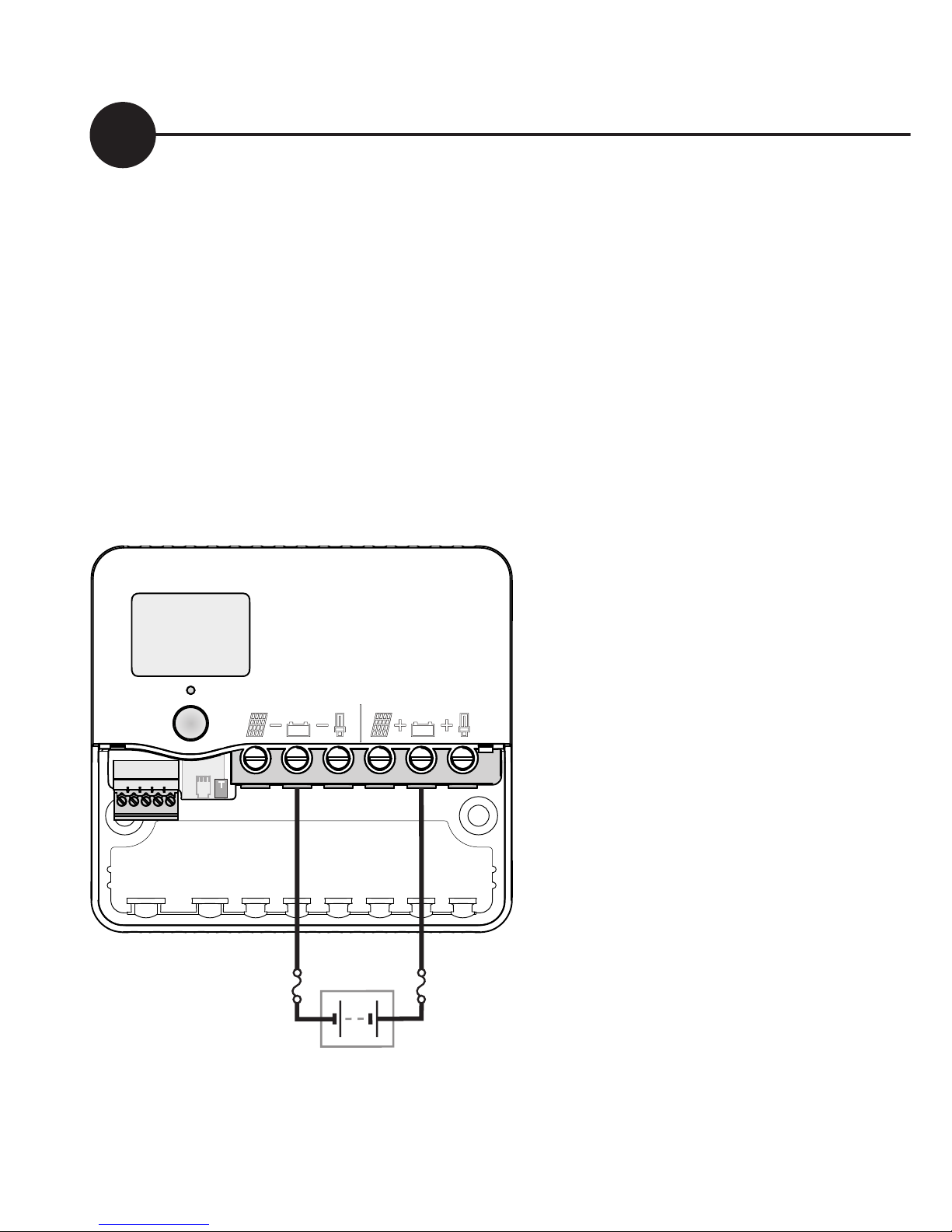
a. Connect the battery first. Positive to Battery+, Negative to
Battery -. If the display comes on, then connection is correct.
(see figure 4)
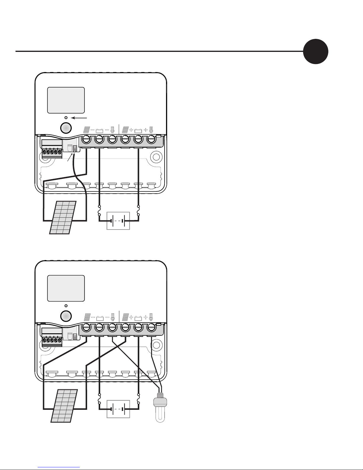
b. Connect the negative (-) wire from the solar panel(s) to the
solar panel negative (-) terminal.
!"#$
27%8
BO OST
V
T
Battery
+
–
Display comes on
Connect
Battery
1
* *
*For safety, most installation
standards require fuses or
circuit breakers on both sides
of the battery.
For other connections, see the
reference manual.
WARNINGS:
•
The controller can
be damaged quickly by
reverse connection of the
solar array in 32, 36 and
48V systems. Test first to
avoid damage.
•NEVER connect batteries or inverters to the load
terminals
Fig. 3
Page 7
7
Dingo Pup User Guide
c. Test the solar panel connection
by touching the positive (+)
wire from the solar panel onto
the Test terminal (T).
•If the alarm led does not flash
then it is OK.
•If the alarm led flashes quickly
then it is not OK. Check the
polarity and test again. (There
must be some light on the solar
panels for this test to work).
If OK connect to the Solar
positive (+) terminal.
d. If the load connection is being
used, connect the negative (-)
wire from the DC load circuit
to the load negative (-) terminal
and the positive load wire to
the load positive (+) terminal.
Test the load circuit.
Check the
load polarity
e: Set the system voltage and Pup
Address.
(see page 10)
f: Connect the Pup to the Dingo
accessory port.
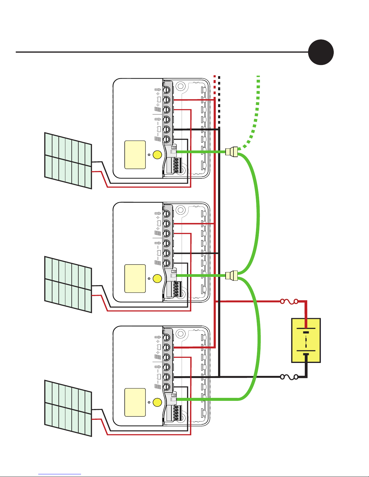
(Multiple Pups
can be connected in a daisy chain
manner by using a 3 way female
adaptor and a short cable as
shown in figure 6 on page 15)
.
Fig. 4
!"#$
27 %8
BOO ST
V
T
Battery
+
–
flashes if wrong
Test
Solar
2
Solar
–
test
here
+
!"#$
27 %8
BOO ST
V
T
Battery
+
–
Connect
Load
3
Solar
–
+
Load
+
–
Page 8
Dingo Pup User Guide
8
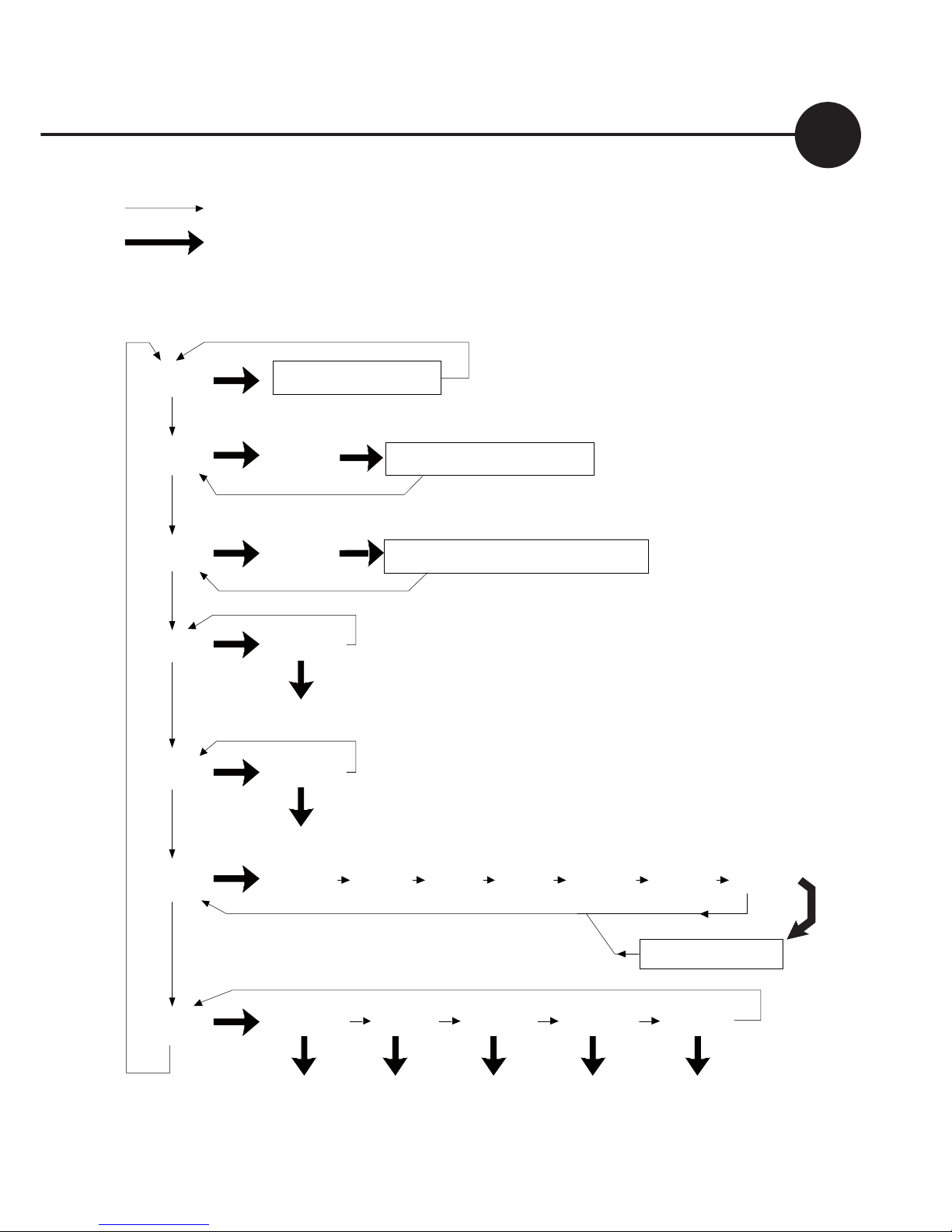
You can move around the
menus system (see figure
5) and change settings using
the button on the front of
the controller..
A short push tells the
controller to advance to the
next menu item or setting
value. To do a short push,
press on the button on the
front of the controller, and
release it immediately.
A long push “selects”,
moving into a sub-menu
or allowing you to change
settings. To do a long push,
press the button, holding
it down until the menu
changes (about one second).
Getting back
Wherever you are in the
menu system, a series of
short-pushes will bring
you back to the top-level
menus without changing
any settings. There are two
exceptions: when a number
is flashing during setting
adjustment (see page 12)
and when you see the word
“EXIT” in the “HISTORY”
sub menu - see page 22.
Using the Menu System
REVERSE & FAST FORWARD
If you overshoot the setting you want and need to go back, you can
use reverse. Do a long push. The number stops flashing. Do another
long push. The number starts flashing again but this time goes down.
More than 5 quick pushes will start the fast forward mode.
To return to normal mode, stop pushing for 1 second.
Page 9
9
Dingo Pup User Guide
Thick arrow = long push
Thin arrow = short push
SET
ADDR TIME VOLT PROG BCAP
Set Set Set Set Set
DATA
VMAX VMIN FTIM SOC TEMP SOLV HIST
History Data
OUT
INT
Clear
IN
INT
Clear
LOAD
LINT
Low Battery Disconnect
CHRG
CINT
Generator Control
BATV
Regulator State
Fig. 5
Page 10

Dingo Pup User Guide
10
Choosing your settings
Set the Pup address and configure the Pup for independent-mode
operation before joining it to the Dingo system.
Each Pup must have its own address. After setting the address
(ADDR), set the system voltage (VOLT) and the correct program
(PROG) for your battery, and configure any advanced settings.
1. Set the Address
Short-push until the display shows “SET”.
a. Long-push once and the display will show “ADDR”.
b. Long-push again, and the address will start flashing.
c. Short-push until the address shown is correct. If you reach 9,
it will cycle back to 0 (unset). Choose the next address after
any other Pups already in use.
d: When the address is correct, long-push to set it.
2. Set the Time
Short-push to move from “ADDR” to “TIME”.
a. Long-push at TIME, and the time will start flashing.
(The time
is displayed in hours and tenths of hours. For example, “6.5” means
6:30am, and “13.1” means 1:06pm)
b. Short push until the time is correct. I
c. When the time shown is correct, long-push to set it.
Note: The time setting is used for the system history, and, in program
4, by the event controller. The time setting does not affect battery
charging.
Page 11
11
Dingo Pup User Guide
Programs
0: Liquid Electrolyte Battery with Low Battery Disconnect option (p.12)
1: Sealed batteries (AGM or Gel) with Low Battery Disconnect option
2: Liquid Electrolyte Battery with Light Controller option
(see p.12)
3: Sealed batteries (AGM or Gel) with Light Controller option.
4: Customised setup. Choosing this program will require you to set a
number of additional parameters.
(see Reference Manual)
3. Set the System Voltage
Short-push to move from “TIME” to “VOLT”.
a. Long-push and the voltage will start flashing.
b. Short-push until the voltage is correct for your battery. If
you pass 48V, it will cycle back to 12V.
c. When the voltage shown is correct, long-push to set it.
4. Set the System Program
Short-push to move from “VOLT” to “PROG”.
The program number determines battery regulation settings if the Pup
becomes separated from the Dingo System. See page 22 for details.
a. Long-push and the program number will start flashing.
b. Short-push to select the best program for your batteries:
c.
When the program shown is correct, long-push to set it.
4. Set any advanced (program 4) settings
Information about the “REG”, “MODE” and “EVNT” settings
is in the Pup reference manual. Contact Plasmatronics
support or download the reference manual from the
Plasmatronics web site..
Page 12

Dingo Pup User Guide
12
Light Controller Option
(Program 2-3)
The built in light controller can
switch lights on at night. When
the voltage from the solar array drops, the Light Controller
function will switch on power
to the load terminals. (The
solar panel voltage is used to
sense the light level.)
If the battery voltage drops too
low, the low battery disconnect
function turns the lights off regardless.
The light controller option will
only work on the Pup if a solar array is connected to the
charge terminals because it
uses the voltage accross the array to sense light level.
To use the Light Controller option, choose program 2 or 3.
If you have connected lights
to the load terminals, they will
switch on at dusk and switch
off at dawn
Low Battery Disconnect
(Program 0-1)
To prevent battery damage
due to overdischarge, the Pup
has a Low Battery Disconnect
(LBD) function which can be
set to turn off the load terminal
if the battery falls below a preset voltage for a period of time.
Short-term battery voltage
fluctuations caused by motors
starting etc. will not activate
LBD. Once the battery has
recharged to a safe level, the
load will automatically switch
on again. This may take some
time.
You do not have to use this feature and the Pup will operate
without it. To use Low Battery
Disconnect, you need to connect your load to the regulator as described on page 7, and
ensure that you have chosen a
program 0 or program 1
Page 13

13
Dingo Pup User Guide
Load Control Menu
Long push on LINT to enter
the Load Control Menu:
LSET: long push to turn the
Load terminal ON or OFF.
In Program 4, more Load
Terminal control options are available (LOFF,
LON,LDEL), and more Load
Function options are available in the MODE menu.
See the Dingo or Dingo Pup
reference manual for more
information.
Generator Control
The G terminal on the Pup
is controlled by the Pup
battery voltage in Program
0-3. Long push on CINT to
enter the Generator Control
Menu:
GSET: long push to turn
the G terminal ON or OFF.
Short push to advance to
GRUN: long push to adjust
the generator exercise
period (default 1.0 hour).
Short push to advance to
GDAY: long push to adjust
the days between generator
exercise events (default 0,
not enabled).
In Program 4, more
Generator Terminal and
Generator Function
options are available. See
the Dingo or Dingo Pup
reference manual for more
information.
Note - NEVER connect
batteries or inverters to
the load terminals of the
controller. They will cause
heavy current flow which
may damage the controller.
Page 14

Dingo Pup User Guide
14
the Pup. If it is not present,
check the cable connections
from the Dingo to the Pup
and wait for 2 minutes.
There will also be entries for
SWH5 under LOAD, IN and
OUT.
If the Dingo is using
PROG=4, then the Dingo
ESET must be set correctly.
In Dingo program 4, the
preloaded default setting for
each pup is ESET/SW=0.
This is correct for using
the Pup’s charge terminal
for charge control (or the
Pups load terminal for shunt
regulation). If using the Pups
only for charge control, it
should not be necessary to
change the ESET/SW setting.
Connecting the Pup to the Dingo
If the program selection
(PROG) on the Dingo is
set in the range 0 through
to 3, then the Dingo is
automatically configured
for using the Pups as charge
controllers.
The Dingo may take a short
time to discover a new Pup.
When the Pup is discovered,
there will be an entry on the
Dingo for the charge and
load current and external
amp hours.
For example, if the Pup
address is set to 5, then in
the Dingo CHRG sub menu,
there will be an entry called
SWH5. This is the charge
current in the Pup at address
5, as seen by the Dingo.
If the CHRG/SWH5 entry
is present, it confirms that
the Dingo has recognised
Page 15
15
Dingo Pup User Guide
Battery
+
–
* *
!"#
42 $1
BOO ST
A
T
-
+
SOLAR
ARRAY 1
DINGO
!"#
15 $8
A
T
-
+
SOLAR
ARRAY 2
PUP 1
!"#
17 $8
A
T
-
+
SOLAR
ARRAY 3
PUP 2
Additional Pups >
*
Battery Fuses are required for safety
3 way adaptor
Dingo with Dingo Pup expansion units
Fig. 6
Page 16

Dingo Pup User Guide
16
When more charge current
is required than can be controlled by one Dingo, then
the array can be split. Dingo
Pups can carry the current
from these extra sub arrays.
The way this is set up is
shown in fig.6 on page 15.
The Dingo controls the
Pups. It tells them when to
turn on or off. When the
battery voltage is below
the regulation point, all
Pups will be on. When
the battery voltage gets to
the regulation point, the
Dingo will turn off the Pups
progressivly to reduce the
charge current so as to
maintain the regulation voltage. If the load increases or
the insolation reduces, then
Pups will be turned back on
until a balance is restored.
The Expanded Dingo System
The Pups report back their
current to the Dingo which
displays the total current in
the system. It also shows
the individual contibutions
from each device.
The Dingo and the Pups are
connected together with a
cable. If a Pup becomes disconnected from the cable,
then it will regulate like an
independant Dingo.
A system based on a Dingo
2020N is negative ground.
This means that the battery
negative terminals are all
connected together. Switching is done on the positive
side.
A Pup may also be operated
as an external switch, controlled by the event, alarm
or load disconnect outputs
of the parent Dingo.
Page 17

17
Dingo Pup User Guide
Dingo Bus Accessories
It is not possible to use any
Dingo Bus accessories with the
Pup in independant mode.
Accessories such as shunt
adaptors and computer
interfaces can be connected to
the Dingo connection bus, but
they communicate with the
Dingo, not the Pups. However,
the Pup information can be
accessed via the Dingo.
External Battery
Temperature Sensor
(DT or DTB).
Pup temperature input has
no effect on battery charging
when the Pup is part of a Dingo
System.
The DT is a plastic-cased unit
for direct attachment to the
battery wall. The DTB has a
bolt-on lug for attaching to
the battery terminal (either
terminal) It connects to the
T+ and T- inputs on the green
plug-in terminal block under
the wiring cover. See Section
7.4.3 of the reference manual
for details. Independent mode
only.
Page 18

Dingo Pup User Guide
18
Monitoring your
system
The Pups monitoring functions
provide you with information
about what that Pup has done.
The overall system information
is kept by the Dingo.
How much energy has
this Pup collected today?
The IN screen shows how
many Amp hours have been
collected by the Pup today.
How much energy has
this Pup used today?
The OUT screen shows how
many Amp hours the Pup load
has used today.
What voltage did the
battery reach?
VMAX shows today’s maximum voltage since midnight;
VMIN
shows today’s minimum
voltage. Both are in the DATA
sub-menu.
The actual battery voltage is
shown on the BATV screen.
What is the Pup’s charge
current?
The CHRG screen displays the
charge current.
What is the Pup’s load
current?
The LOAD screen displays the
load (or discharge) current.
Are components working
correctly?
A battery temperature sensor
can be connected to
the Pup to
improve regulation if it is operating on its own. If this sensor is
installed, the
battery temperature is shown on the TEMP
screen in the DATA sub-menu.
(If it is blank, no temperature
Page 19

19
Dingo Pup User Guide
sensor is attached).
To test your solar array, the
SOLV screen in the DATA menu
shows the open-circuit voltage
of the solar array.
(Note: charging is interupted while the SOLV
screen is displayed - this will
eventually time out to prevent
the controller being left in a non
charging state)
The Data Menu
This is a quick summary of the
screens in the data submenu
which are reached by a long
push on the DATA screen and
the values stored each day by
the history function.
VMAX Maximum battery
voltage since midnight.
VMIN Minimum battery
voltage since midnight.
FTIM Time of day the
controller entered the Float
state if it didn’t begin in float.
SOC This is not relevant
to the Pup as part of a system.
TEMP Temperature being
sensed by the battery temperature sensor (if attached).
SOLV Solar panel open cir-
cuit voltage. NB: charging stops
while displaying this screen.
HIST Entry point for his-
tory data display. At midnight,
IN (Amp hours), OUT (Amp
hours), VMAX, VMIN, FTIM
(Float TIMe) and SOC (State Of
Charge) are stored in the history data and reset. VMAX and
VMIN respond very slowly to
changes in battery voltage. This
allows them to ignore short
term voltage fluctuations.
Page 20
Dingo Pup User Guide
20
Retrieving historical
data
In addition to storing
today’s performance data,
the controller can display
information about the last 99
days of operation. Historical
performance information
can be accessed from the
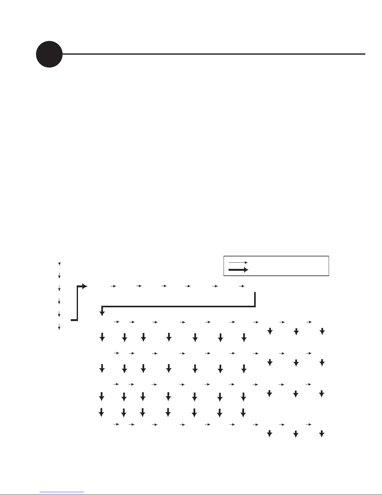
DATA sub menu. After a
long-push on DATA, shortpush until you see HIST.
A long-push on HIST will
put you in “history mode”,
where you can cycle through
each day’s data. In the history
display, DAY 1 is yesterday
and DAY 99 is 99 days ago.
Thin arrow = short push
Thick arrow = long push
BATV
CHRG
LOAD
IN
OUT
DATA
SET
DAY 1 IN OUT VMAX VMIN FTIM SOC NEXT BACK EXIT
DAY 2 DAY 99 DATA
VMAX VMIN FTIM SOC TEMP SOLV HIST
DAY 2 IN OUT VMAX VMIN FTIM SOC NEXT BACK EXIT
DAY 3 DAY 1 DATA
DAY 3 IN OUT VMAX VMIN FTIM SOC NEXT BACK EXIT
DAY 4 DAY 2 DATA
DAY 99 IN OUT VMAX VMIN FTIM SOC NEXT BACK EXIT
...
...
...
...
...
...
...
DAY 1 DAY 98 DATA
Page 21

21
Dingo Pup User Guide
Further information
This controller is capable of
more than what is described in
this user manual.
For information on how to
customise your regulation
setup and set up larger systems,
as well as the many additional
features, consult the Reference
Manual. This is available
from your dealer or can be
downloaded from our website:
www.plasmatronics.com.au.
Independent Mode
When the Pup is not under the
control of a Dingo, it operates
as if it were a Dingo (but without the ability to have accessories connected to it).
The Charge, Load, and Generator terminals may also be
configured for independent
control while the Pup is connected to a Dingo system.
In Program 0-3, the Low
Battery Disconnect and Light
Controller Option operate
independently, as does the
Generator control, and, if a
Dingo is connected, the Dingo
controls the Charge terminals.
Page 22
Dingo Pup User Guide
22
Independent Mode
settings used in Programs
0-3
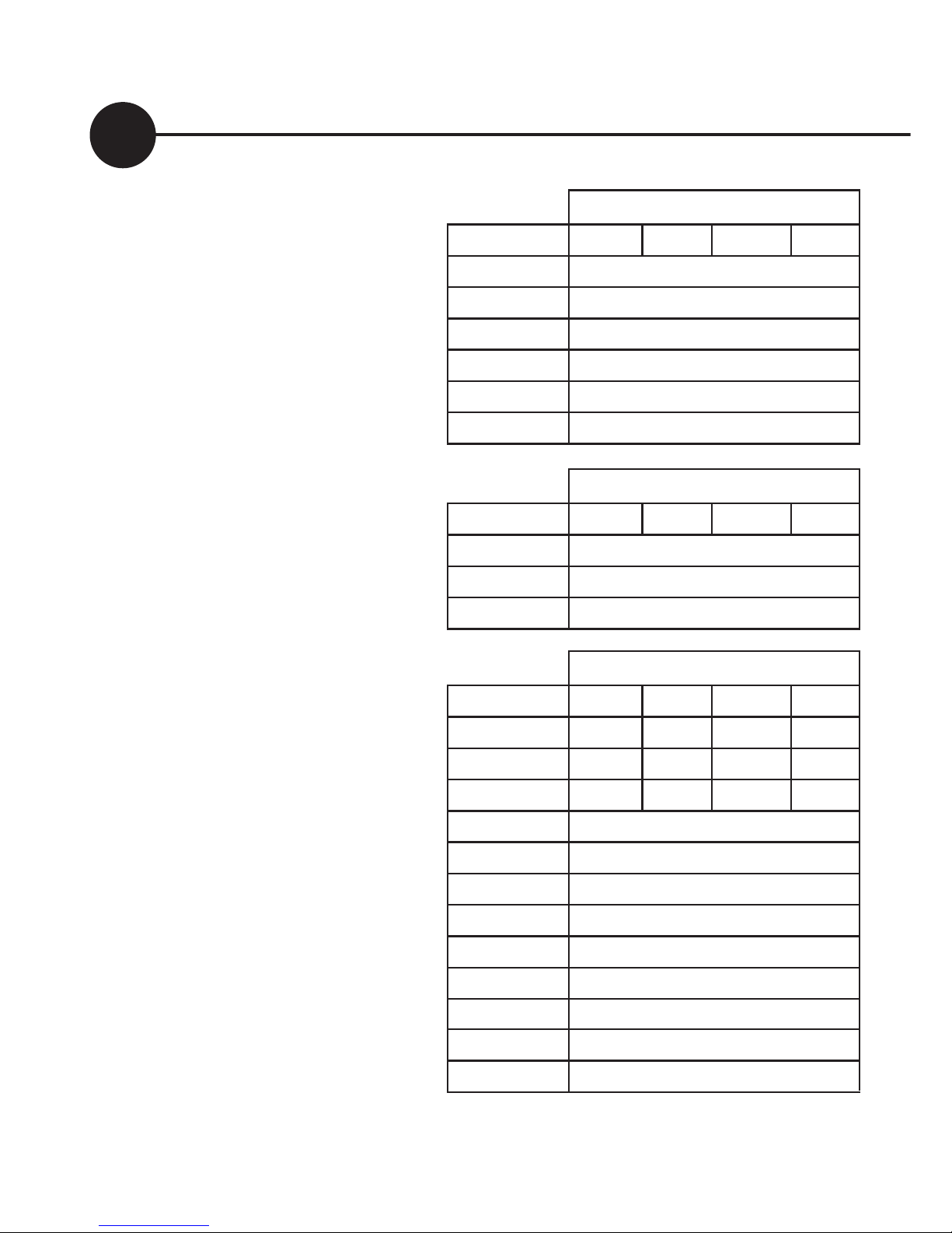
When programs 0-3 are
selected, the controller
automatically uses the values
in the table on the right to
control its operation.
The voltage settings are
shown correct for 12V
operation. For higher
voltages, scale these up (eg.
for a 24V system, multiply
each voltage figure by 2.)
CHRG
Setting for program number
Parameter 0 1 2 3
GMOD 0
G ON (V) 11.5
GOFF (V) 13.8
GDEL (Min) 10
GEXD (Day) 30
GRUN (Hr) 1.0
LOAD
Setting for program number
Parameter 0 1 2 3
LOFF (V) 11.3
L ON (V) 12.8
LDEL (Min) 10
SET/REG
Setting for program number
Parameter 0 1 2 3
BMAX (V) 15.0 14.2 15.0 14.2
EMAX (V) 16.0 14.0 16.0 14.0
ETIM (Hr) 1.0 0 1.0 0
EFRQ (day) 45
ABSV (V) 14.0
ATIM (Hr) 2.0
FLTV (V) 13.8
HYST (V) 0.4
BRTN (V) 12.3
CHRG (A)
20
BFRQ (Day) 15
TCMP 0
Page 23
23
Dingo Pup User Guide
Nominal system voltages 12,24,32,36,48 V
Maximum voltage BAT+ to BAT- 100 V
Max short term voltage BAT+ to BAT- (2 min) 120 V
Maximum voltage SOL+ to BAT- 100 V
Max. voltage LOAD+ to BAT+ 70 V
Max. voltage between the “G” relay terminals 90 V
Max. voltage B+sense to BAT+ +/-30 V
Max. continuous charge current (SOL+) 20 A
Max. continuous load current (LOAD+) 20 A
Max. short term load current (5 minutes) 30 A
Max “G” relay current 300
mA
Battery Temp sensor range -20 to +70
°C
Max. storage temperature 70
°C
Supply Current (device only, 12V) 9 mA
Supply Current (device only, 60V) 15 mA
Supply Current max (with acces.) 26 mA
Meter Accuracy <+/-2% +/-2 digits
Max wire entry size: 16mm2 (6 AWG)
Wire size, Green Terminal Block 0.2-1.3mm2 (26-16AWG)
Specifications
Page 24

Dingo Pup User Guide
24
Plasmatronics Pty Ltd
75 Newman St.
Thornbury 3071
Victoria, Australia
ph (61) 3 94869902
[email protected]
www.plasmatronics.com.au
 Loading...