

Page 1
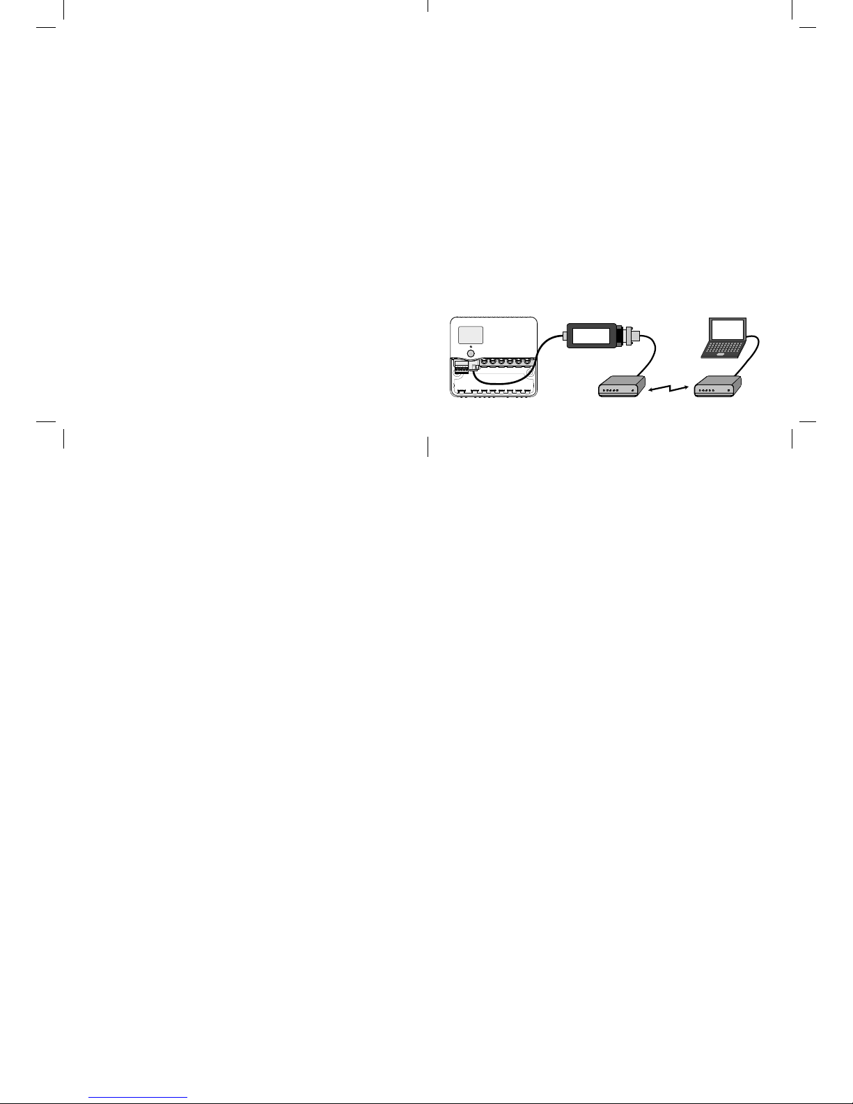
send commands through it to the Dingo. Some commands will result in the Dingo sending data back to the
computer. The D232 also has a loopback command.
Default communication settings:
9600 baud, 8 data bits, Even parity, 1 stop bit. (Modbus
defaults). All communication is Modbus RTU mode.
Modbus ASCII mode is not supported. Default modbus
slave address: 8 Allowed slave addresses: 1-247.
For further information about changing the settings
read the information fi les on the memory stick supplied
or visit www.plasmatronics.com.au
SPECIFICATIONS
Line Speeds 1.2, 2.4, 4.8, 9.6,19.2 KBaud
RS232 input levels required >+/- 5V
RS232 drive levels >+/-5V
Min. Load Impedance 3K
Output impedance (TX) 1000 ohm
DC Isolation 500V
Temperature range -20 to +70oC
Supply current 5mA (from Dingo supply)
1.5mA from RS232 TX line
D232
Computer Interface for Dingo controllers
The D232 is a device to allow the Dingo to communicate with a modem or computer via an RS232 serial
port.
Description
The D232 is primarily intended for data communication between a computer and a Dingo via a modem. It allows serial
communication at speeds from 1200 to 19200 baud. The line
speed (baud rate) is adjusted using a computer. It is stored
in the D232 and is retained when the power is disconnected.
The modem (or computer if no modem) baud rate must be
the same as the baud rate set on the D232 for communication to occur. The RS232 port on the D232 is electrically
isolated. This reduces the risk of ground confl icts. The Dingo
Dcab
Cable
"!46
<
BOOST
V
T
DINGO
D232
Serial Interface
Serial Cable
Modem Modem
Link
Page 2
supplies the power to operate it’s side of the D232. On
the other side, a small amount of power will be drawn
from the serial port of the connected device.
Connection
On the RS232 side, the D232 is confi gured as a DTE
interface. This means that it can be connected to a
modem directly without the use of a null modem cable.
The D232 has a 9 pin male D connector (DB9M). If you
want to connect to a computer directly you will need a
null modem cable. To extend the length of an existing
cable a minimum of three wires are needed : TX (pin
3), RX (pin 2) and Signal Ground (pin 5) [Note: pin
numbers are for the D232 end of the cable]. Handshake lines are not used for fl ow control.
On the Dingo side, connection is made via 6 wire
shielded cable and modular telephone style connectors. A ‘Dcab’ cable is supplied in the box. Longer
cables can be supplied or the user can make their own
if they have the correct tools. Orient the connectors so
that pin 1 at one end goes to pin 1 at the other end.
(When you hold both connectors so that they are facing
you and the same way up, then the same color wire will
be on the same side -copy the cable supplied.)
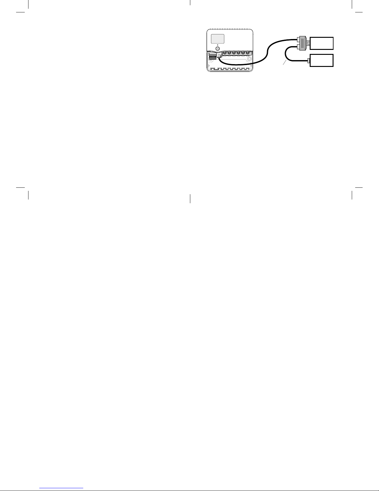
To connect two or more accessories to a controller, use
a US standard 6 position telephone double adaptor
and a Dcab cable as shown above. Only one D232 or
DUSB can be used in a system.
Software
Windows software is supplied on the USB memory
stick in the box. This can also be downloaded from
www.plasmatronics.com.au
Protocol
The D232 uses a subset of the Modbus RTU protocol
and is implemented as a slave. It does not send data
to the computer unless requested. The computer can
D232
DSA
2F to 1M Adaptor
Dcab CABLE
Dcab CABLE
"!46
<
BOOST
V
T
DINGO
 Loading...