

Page 1

D2020N
Negative Ground
20A Max. Charge
20A Max. Load
Advanced Solar Charge Controller
DINGO User Guide
Read this before installing
Ver 1.4 160906
Page 2

D2020N User Guide
2
This is not an MPPT device:
There is no voltage conversion.
Suitable array max power voltages are:
•12 volt system 16-19V
• 24 volt system 32-38V
• 48 volt system 64-76V.
Page 3
3
D2020N User Guide
Wiring Instructions 6
Monitoring your System 12
Using the Menus 8
Choosing your Settings 10
Install your controller:
• Vertically, where air can circulate around it
• In a dry environment out of direct sunlight
• Away from flammable gases or liquids
• Away from spiders, wasps or other insects
which might make nests in it
• Do not use countersunk screws to mount
Page 4
D2020N User Guide
4
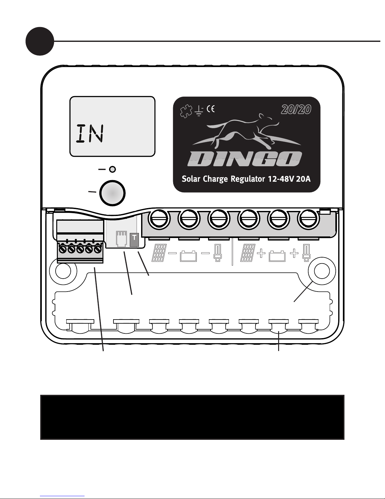
Screw wires into the high current terminals
tightly in the order listed on page 6.
Fig. 1
Warning: This controller is for DC current ONLY
BOOST
Di sp la y
Alarm LED
Terminals for G and sensor wires
(plug in terminal block)
Accessory port
Mounting holes
Cable tie
posts
T
Test terminal
Ah
Button
See page 8
Page 5
5
D2020N User Guide
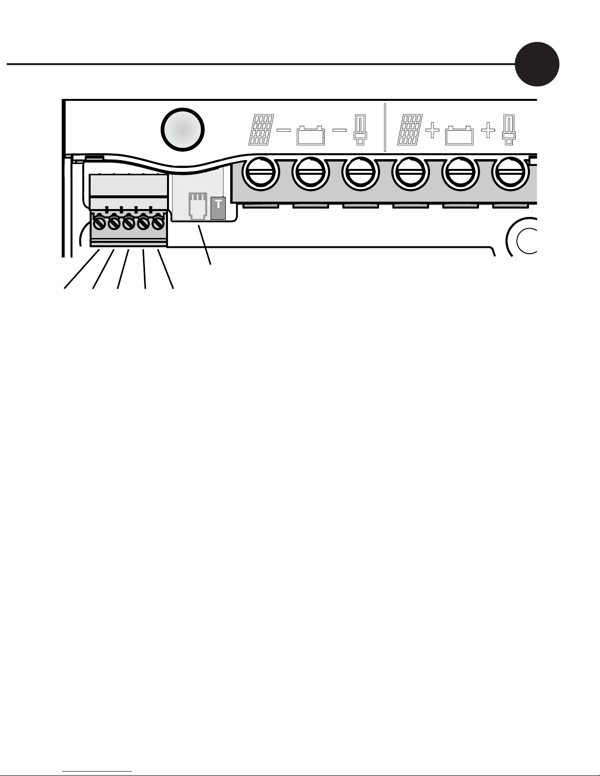
Basic Connection Order
1. Connect Battery
2. Test Solar Polarity
3. Connect Solar
4. Connect Load
After connection you must set the system voltage (p10)
T
BATTERY-
SOLAR+
BATTERY+
LOAD+
‘G’ Terminals
Sensor T+
Temperature T-
B+ Sense
LOAD-
SOLAR-
‘G’ Terminals
Accessory Port
Test terminal
Fig. 2
Page 6
D2020N User Guide
6
Wiring instructions
For safety and to avoid damage, connection of wires must be
done in the following order.
All connections must be tight!
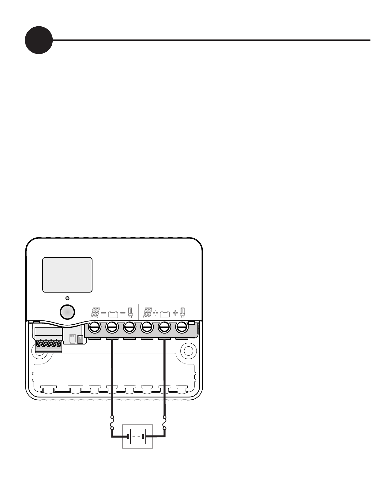
a. Connect the battery first. Positive to Battery+, Negative to
Battery -. If the display comes on, then connection is correct.
(see figure 3)
b. Connect the negative (-) wire from the solar panel(s) to the
solar panel negative (-) terminal.
BO OST
V
T
Battery
+
–
Display comes on
Connect
Battery
1
* *
*For safety, most installation
standards require fuses or
circuit breakers on both sides
of the battery.
For other connections, see the
reference manual.
DO NOT CONNECT INVERTERS TO
THE LOAD TERMNIAL
WARNING:
The controller can be
damaged quickly by
reverse connection of
the solar array in 32V,
36V and 48V systems.
Test first to avoid
damage.
Fig. 3
Page 7
7
D2020N User Guide
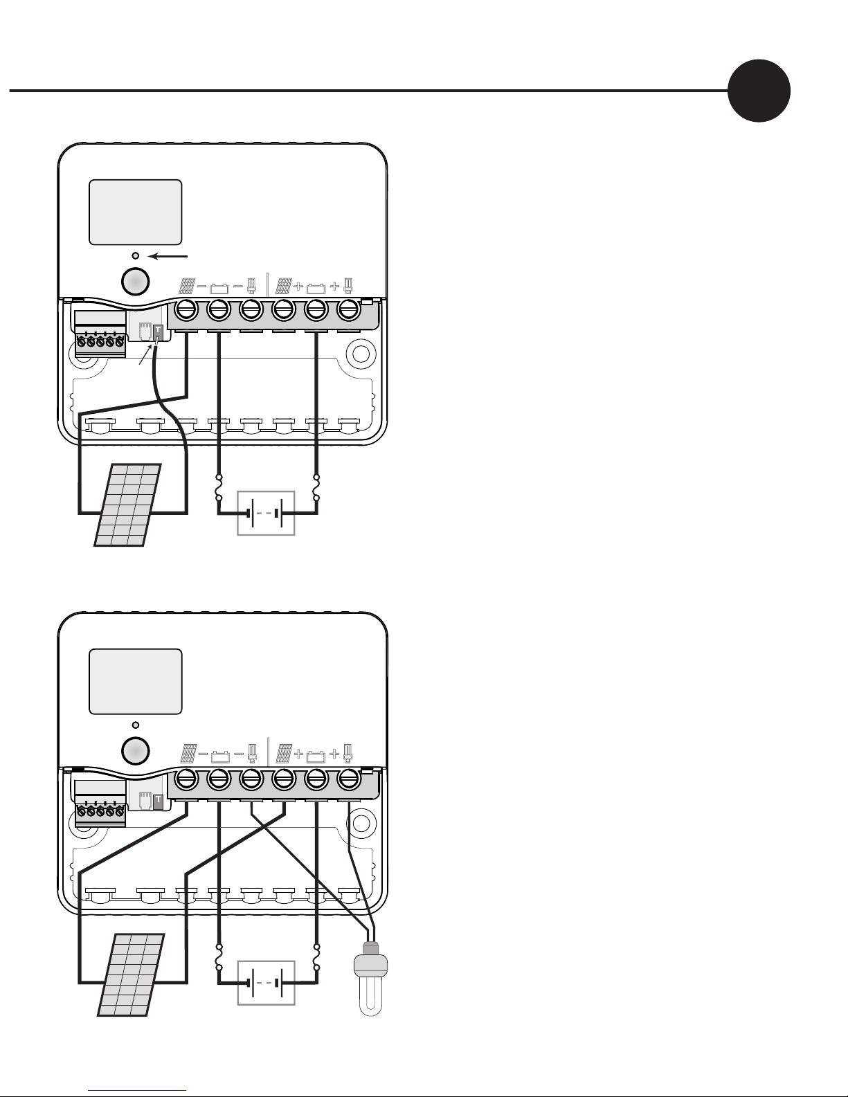
c. Test the solar panel connection
by touching the positive (+)
wire from the solar panel onto
the Test terminal (T).
•If the alarm led does not flash
then it is OK.
•If the alarm led flashes quickly
then it is not OK. Check the
polarity and test again. (There
must be some light on the solar
panels for this test to work).
If OK connect to the Solar
positive (+) terminal.
d. Connect the negative (-) wire
from DC load circuit to the
load negative (-) terminal and
connect the positive wire from
the load to the load positve
(+) terminal. Test that the load
circuit works.
The controller
is protected against load short
circuits, but cannot protect your
load devices if you reverse the
connection to them. Now, set
the system voltage - see pg.10
N
ote: The controller is protected against short
circuits on the solar input.
Fig. 4
BOO ST
V
T
Battery
+
–
flashes if wrong
Test
Solar
2
Solar
–
test
here
+
BOO ST
V
T
Battery
+
–
Connect
Load
3
Solar
–
+
Load
+
–
Page 8

D2020N User Guide
8
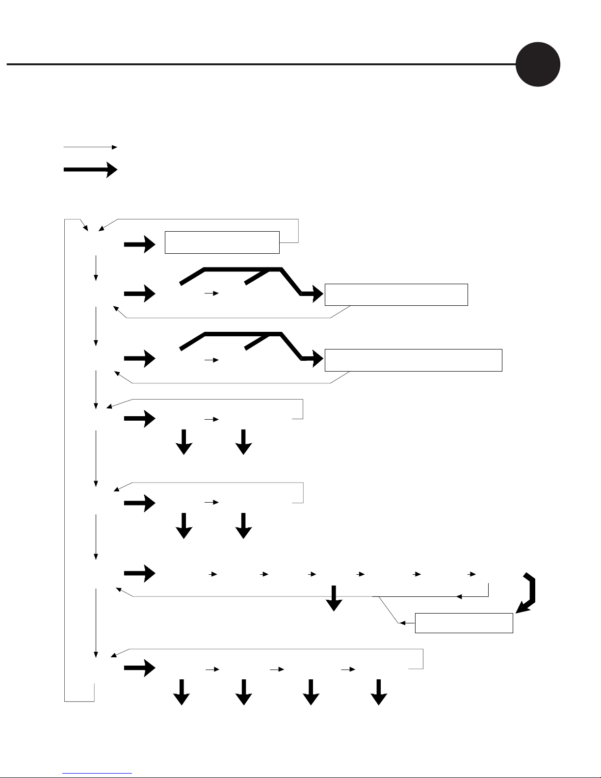
Using the Menu System
You can move around the menu system and change settings
using the button on the front of the controller. There are
seven top-level menu items in the menu system (BATV,
CHRG, LOAD etc - see figure 5). Each menu item provides
access to a sub-menu, and some of these sub-menus lead
again to further sub-menus.
A short push tells the controller to advance to the next
menu item or setting value. To do a short push, press on
the button on the front of the controller, and release it
immediately.
A long push “selects”, moving into a sub-menu or allowing
you to change settings. To do a long push, press the button,
holding it down until the menu changes (about one second).
Getting back
Wherever you are in the menu system, a series of shortpushes will bring you back to the top-level menus without
changing any settings. There are two exceptions: when a
number is flashing during setting adjustment (see page 10)
and when you see the word “EXIT” in the “HISTORY” sub
menu - see page 16.
Note: ‘external’ screens do not appear if there are no
accessories attached. If an accessory is attached, the
screen names will indicate the accessory type.
Page 9
9
D2020N User Guide
Menu System (Programs 0-3 )
Thick arrow = long push
Thin arrow = short push
SET
TIME VOLT PROG BCAP
Set Set Set Set
DATA
VMAX VMIN FTIM SOC TEMP SOLV HIST
History Data
Adjust
OUT
INT External
Clear Clear
IN
INT External
Clear Clear
LOAD
LINT External
Low Battery Disconnect
CHRG
CINT External Generator Control
BATV
Regulator State
Fig. 5
Page 10
D2020N User Guide
10
Choosing your settings
Failure to correctly set the system voltage (VOLT) and select the
correct program (PROG) for your battery may result in damage
to the battery or connected equipment. Follow this procedure:
1. Set the Time
a. Short-push until the display shows “SET”.
b. Long-push once and the display will show “TIME”.
c. Long-push again, and the time will start flashing. (Note that
the time is displayed in hours and tenths of hours. For
example, “6.5” means 6:30am, and “13.1” means 1:06pm.)
d. Short-push until the time shown is correct. If you reach 23.9
(11.54pm), it will cycle back to 0.0 (midnight).
e. When the time shown is correct, long-push to set it.
Note: time setting does not affect battery charging.
REVERSE & FAST FORWARD
If you overshoot the setting you want and need to go back, you can
use reverse. Do a long push. The number stops flashing. Do another
long push. The number starts flashing again but this time goes down.
More than 5 quick pushes will start the fast forward mode.
To return to normal mode, stop pushing for 1 second.
2. Set the System Voltage (! Important)
a. Short-push to move from “TIME” to “VOLT”.
b. Long-push and the voltage will start flashing.
c. Short-push until the voltage is correct for your battery. If
you pass 48V, it will cycle back to 12V.
Page 11
11
D2020N User Guide
Programs
0: Liquid Electrolyte Battery with Low Battery Disconnect option (p.18)
1: Sealed batteries (AGM or Gel) with Low Battery Disconnect option
2: Liquid Electrolyte Battery with Light Controller option (see p.19)
3: Sealed batteries (AGM or Gel) with Light Controller option.
4: Customised setup. Choosing this program will require you to set a
number of additional parameters. (see Reference Manual)
d. When battery voltage is correct, long-push to set it.
3. Set your program (! Important)
The Dingo comes with a number of pre-set programs, to
make configuration easy for most installations.
a. Short-push to move from “VOLT” to “PROG”.
b. Long-push and the program number will start flashing.
c. Short-push to select the best program for your batteries:
d.
When the program shown is correct, long-push to set it.
4. Set the Battery Capacity
Note: BCAP setting does not affect battery charging.
a. Short-push to move from “PROG” to “BCAP”.
b. Long-push and the battery capacity will start flashing.
c
. Short-push to choose the correct battery capacity for your
system in Ampere hours (Ah). (Settings over 1000Ah display
in thousands - e.g. 1600 Ah shows as “1.6”. Note: Look for
the decimal point, eg 20=20Ah, 20.0=20,000Ah) If unsure,
check your battery manual or consult your battery supplier.
d. Long-push to keep the chosen value
Page 12

D2020N User Guide
12
Monitoring your system
This controllers’s advanced monitoring functions provide you
with unparalleled information about your system. Here are some
questions that your controller can answer:
How much energy have I collected today?
The top-level IN screen shows how many Amp hours have been
collected today.
How much energy have I used today?
The top-level OUT screen shows how many Amp hours the load
has used today.
What voltage did the battery reach?
VMAX shows today’s maximum voltage since midnight; VMIN
shows today’s minimum voltage. Both are in the DATA sub-menu.
The actual battery voltage is shown on the BATV screen.
What is the charge current?
The top level CHRG screen displays the charge current. This
is the total current from all charge sources. The current which
actually flows through the controller is called internal. In larger
systems, there can be current which does not flow through the
controller. This is called external.
Page 13

13
D2020N User Guide
The CHRG screen displays the sum of the internal and exernal
currents. By doing a long push on the CHRG screen you can see
how much each device contributes to the total charge.
The first screen is called CINT and displays the internal charge.
The next screen(s) display any currents reported by external
devices. (For details, see the reference manual)
What is the load current?
The top level LOAD screen displays the load (or discharge)
current. This is the total current used by all loads. A long push
will display the internal load current (LINT) and any external load
currents.
How full is the battery?
The voltage level of your battery is a good measure of how full it
is, and is shown on the top-level “BATV” screen. Alternatively,
SOC in the DATA sub-menu (long-push on DATA, then three
short-pushes) uses amp-hour, voltage & temperature data to
provide an estimate of the state of charge. (Warning: SOC will
be meaningless if the controller is not measuring all the charge
and discharge from the battery. For example, if an inverter
is connected directly to the battery, an external shunt and an
external shunt adaptor is needed so that the controller can
include the inverter current in its calculations. There will also be
errors due to temperature and the age of the battery).
Page 14

D2020N User Guide
14
What time did the battery finish charging today?
The FTIM screen in the DATA sub-menu shows the time the
controller finished charging and entered the “float” state (see
page 17). If the controller did not change from absorption to
float, then this will show as a dash (“-”).
For example, if the controller started the day in “float” mode and
stayed there all day, the FTIM screen will show “-”.
Are components working correctly?
A battery temperature sensor can be connected to your
controller
to improve regulation. If this sensor is installed, the
battery temperature is shown on the TEMP screen in the DATA
sub-menu. (If it is blank, no temperature sensor is attached).
To test your solar array, the SOLV screen in the DATA menu
shows the open-circuit voltage of the solar array.
(Note: charging
is interupted while the SOLV screen is displayed. If the controller is
left in this state it will automatically turn the charge back on after a
period of time. This is to prevent the controller being left in a non
charging state)
How much heat can the Dingo take?
The Dingo can operate at full charge and load current up
to an ambient temperature of 50oC (122oF). Take care, the
temperature inside a box will be higher than ambient. For
information on derating see apendix A4 of the Dingo Reference
manual. The Dingo will also work down below -20oC (-4oF).
Page 15

15
D2020N User Guide
The Data Menu
This is a quick summary of the screens in the data submenu
which are reached by a long push on the DATA screen and the
values stored each day by the history function.
VMAX Maximum battery voltage since midnight.
VMIN Minimum battery voltage since midnight.
FTIM Time of day the controller entered the Float state
if it didn’t begin in float (see page 17).
SOC Percentage estimate of the state of charge of the
battery based on amp hours in/out. A very rough ‘fuel
gauge’.
TEMP Temperature being sensed by the battery temperature
sensor (if attached).
SOLV Solar panel open circuit voltage.
NB: charging stops while displaying this screen.
HIST Entry point for history data display.
IN The amount of energy collected in Amp hours today.
OUT The amount of energy used in Amp hours today.
At midnight, IN, OUT, VMAX, VMIN, FTIM and SOC are stored
in the history data and reset. VMAX and VMIN respond very
slowly to changes in battery voltage. This allows them to ignore
short term voltage fluctuations.
Page 16
D2020N User Guide
16
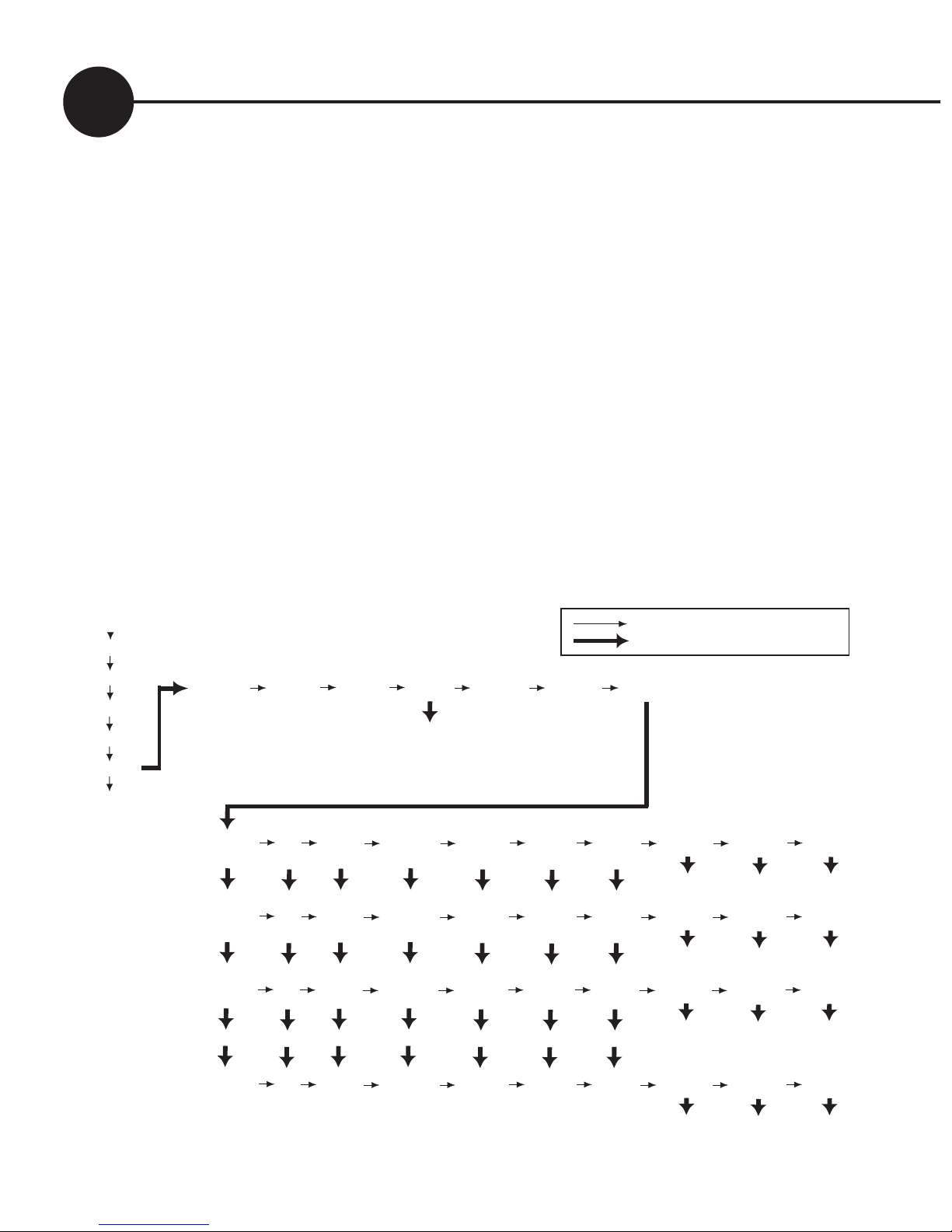
Retrieving historical data
In addition to storing today’s performance data, the controller
can display information about the last 99 days of operation.
Historical performance information can be accessed from the
DATA sub menu (see figure 6). After a long-push on DATA,
short-push until you see HIST. A long-push on HIST will put you
in “history mode”, where you can cycle through each day’s data.
In the history display, DAY 1 is yesterday and DAY 99 is 99 days ago.
(Note: the controller actually stores 512 days data, but this is only accessible via the
computer interface)
History Mode
Thin arrow = short push
Thick arrow = long push
BATV
CHRG
LOAD
IN
OUT
DATA
SET
DAY 1 IN OUT VMAX VMIN FTIM SOC NEXT BACK EXIT
DAY 2 DAY 99 DATA
VMAX VMIN FTIM SOC TEMP SOLV HIST
DAY 2 IN OUT VMAX VMIN FTIM SOC NEXT BACK EXIT
DAY 3 DAY 1 DATA
DAY 3 IN OUT VMAX VMIN FTIM SOC NEXT BACK EXIT
DAY 4 DAY 2 DATA
DAY 99 IN OUT VMAX VMIN FTIM SOC NEXT BACK EXIT
...
...
...
...
...
...
...
DAY 1 DAY 98 DATA
Long push to adjust
(0-100%)
Fig. 6
Page 17

17
D2020N User Guide
The Battery Charging Process
When charging your battery, the controller moves automatically
through the following charging sequence:
Boost phase - In this phase, all available charge is used to
charge the battery as quickly as possible. When the battery is
charging in the Boost phase, the “Boost” indicator appears on
the controller’s screen.
Absorption phase - The battery is nearly full. To avoid excess
gassing, the charge current is now adjusted to keep the
battery at a lower, constant voltage.
Float phase - The battery is fully charged, so the controller now
maintains the battery at a lower voltage. If the battery voltage
drops below a pre-set point, the controller will move back to
the Boost phase automatically.
For flooded batteries, the controller will occasionaly do a
deliberate overcharge of the battery. This is called Equalisation.
This phase helps level the charge between the different cells
inside the battery by overcharging the battery for a short period.
It will do this several times each year.
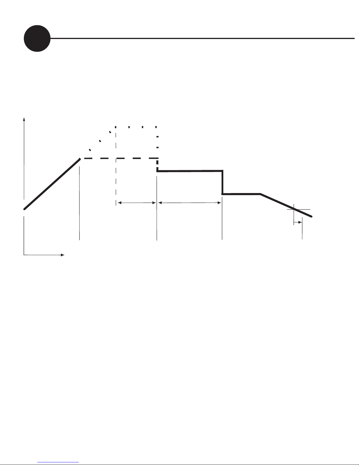
Figure 7 shows how the voltage of the battery varies during the
charging process. The regulation settings shown in the diagram
(BMAX, ETIM etc) can all be set individually in Program 4. This
caters for the requirements of unusual installations.
Page 18
D2020N User Guide
18
Battery Voltage
Time
BOOST EQUALISATION ABSORPTION FLOAT BOOST
BRTN
FLTV
ABSV
EMAX
BMAX
ETIM ATIM
A long push on BATV will show the regulator state.
(BOST=Boost, EQUL=Equalise, ABSV=Absorption, or
FLOT=Float). A long-push on that state will manually advance
the PL into the next state. Or, to return to the BATV screen
without changing the state, do a short push.
Low Battery Disconnect (LBD)
To prevent battery damage due to overdischarge, the controller
has an optional Low Battery Disconnect (LBD) function which
can be set to turn off the load terminal if the battery falls below a
pre-set voltage for a period of time.
For more information see the Reference Manual. The pre-set
values provided by choosing Programs 0, 1, 2 or 3 will usually
ensure good charge control without a complex setup process.
Fig. 7
Page 19

19
D2020N User Guide
Short-term battery voltage fluctuations caused by motors starting
etc. will not activate LBD. Once the battery has recharged to a
safe level, the load will automatically switch on again. This may
take some time.
You do not have to use this feature, and the controller will still
operate effectively without it.
To use Low Battery Disconnect, you need to connect your load
to the regulator as described on page 7, and you should also
ensure that you have chosen a program where the Low Battery
Disconnect feature is activated - see page 11.
Note - NEVER connect batteries or inverters to the load
terminals of the controller. They will cause heavy current flow
which may damage the controller.
Light Controller Option
There is a built in light controller which can switch lights on at
night. When the voltage from the solar array drops, the Light
Controller function will switch on power to the load terminals. If
you have connected lights to the load terminals, they will switch
on at dusk and switch off at dawn. (The solar panel voltage is used
to sense the light level.)
If the battery voltage drops too low, the low battery disconnect
function overrides the light controller and turns the lights off.
To use the Light Controller option, choose a program which
enables this function, as described on page 11.
Page 20

D2020N User Guide
20
Further information
This controller is capable of more than what is described in this
user manual.
For information on how to customise your regulation setup and
set up larger systems, as well as the many additional features,
consult the Reference Manual. This is available from your dealer
or can be downloaded from our website.
Accessories
These accessories can enhance the usefulness of your controller.
External Battery Temperature Sensor (DT or DTB)
The DT is a plastic-cased unit for direct attachment to the battery
wall. The DTB has a bolt-on lug for attaching to the battery terminal
(either terminal). It connects to the T+ and T- inputs on the
green plug in terminal block under the wiring cover. See Section
7.4.3 of the reference manual for details.
The following accessories plug into the serial port socket. (RJ11)
External Shunt Adaptor (DSA)
Up to four external shunts can be added to the controller to allow it
to measure larger currents than it is capable of measuring directly. The
shunt adaptor measures the current in a shunt (eg SH200), converts it
to digital information and sends that information back to the controller.
The shunt connection is isolated so the shunt can be placed in any part
of the circuit. Currents up to +/-250A can be read in 0.1A steps.
Page 21

21
D2020N User Guide
Computer/Modem Serial Interface (DUSB, D232)
A serial interface is available which allows the controller to
communicate with a computer or be remote accessed via a modem.
Both USB and RS232 versions are available. This is a quick way to
load settings or extract performance data. All of the data is remotely
accessible, and all settings can be adjusted. Windows based software
is available to download the data. Data can then be loaded into a
spreadsheet or other applications.
DNET
The DNET Ethernet Gateway provides basic read-only access to the
main parameters of the Dingo4040P via both HTTP and SNMP
DRC
The Dingo Remote Control allows all of the functions on the Dingo
to be accessed remotely. Includes built-in audible alarm and display
backlighting.
Other accessories
Check the website, (www.plasmatronics.com.au), for more details of
accessories and the most up to date list of accessories..
Page 22
D2020N User Guide
22
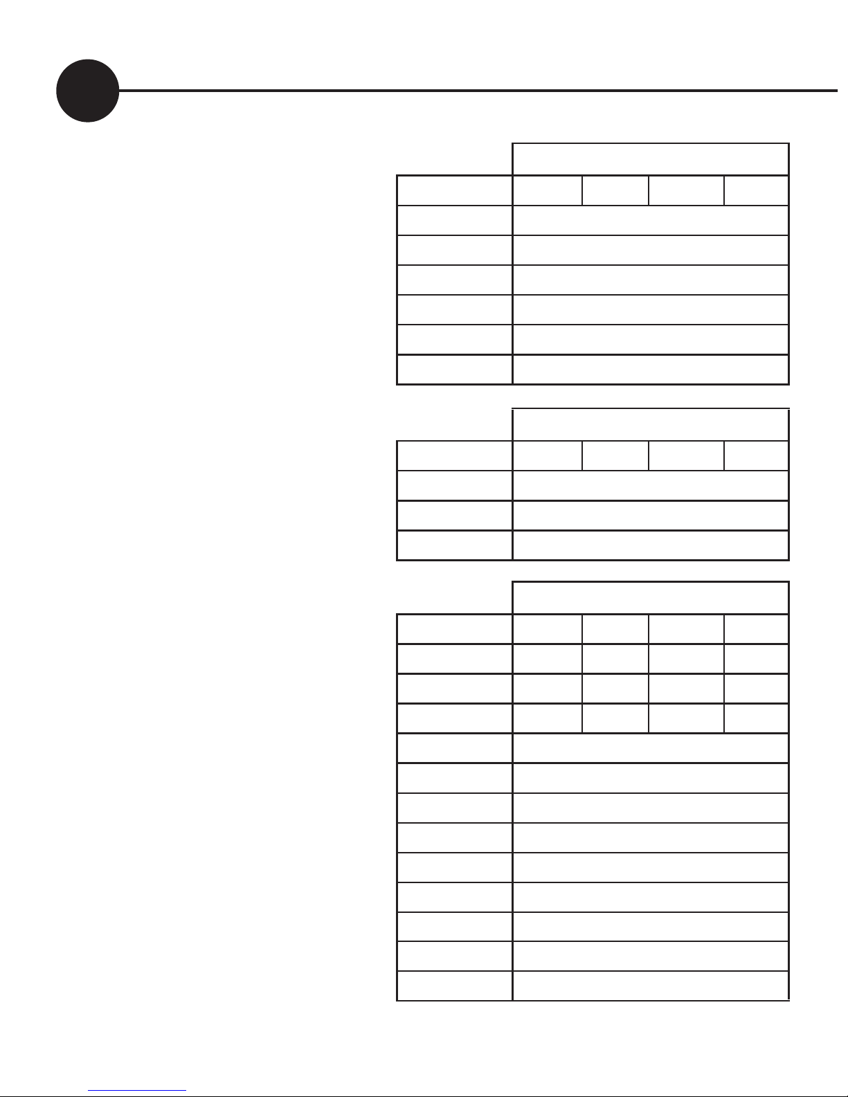
Settings Used in
Programs 0-3
When programs 0-3 are
selected, the controller
automatically uses the values
in the table on the right to
control its operation.
The voltage settings are
shown correct for 12V
operation. For higher
voltages, scale these up (eg.
for a 24V system, multiply
each voltage figure by 2.)
CHRG
Setting for program number
Parameter 0 1 2 3
GMOD 0
G ON (V) 11.5
GOFF (V) 13.8
GDEL (Min) 10
GEXD (Day) 30
GRUN (Hr) 1.0
LOAD
Setting for program number
Parameter 0 1 2 3
LOFF (V) 11.3
L ON (V) 12.8
LDEL (Min) 10
SET/REG
Setting for program number
Parameter 0 1 2 3
BMAX (V) 15.0 14.2 15.0 14.2
EMAX (V) 16.0 14.0 16.0 14.0
ETIM (Hr) 1.0 0 1.0 0
EFRQ (day) 45
ABSV (V) 14.0
ATIM (Hr) 2.0
FLTV (V) 13.8
HYST (V) 0.4
BRTN (V) 12.3
CHRG (A)
20
BFRQ (Day) 15
TCMP 0
Page 23
23
D2020N User Guide
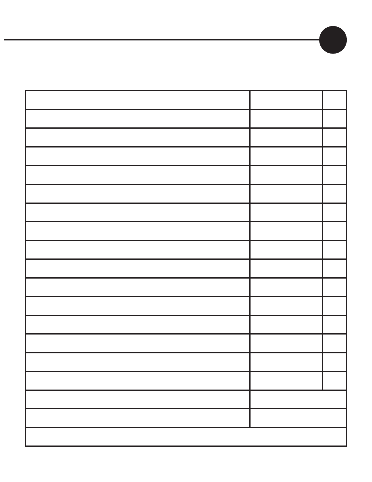
Specifications
Nominal system voltages 12,24,32,36,48 V
Maximum voltage BAT+ to BAT- 100 V
Maximum short term voltage BAT+ to BAT- (2 minutes) 120 V
Maximum voltage SOL+ to BAT- (for a 48V system) 100 V
Maximum voltage LOAD+ to BAT+ 70 V
Maximum voltage between the ‘G’ relay terminals 90 V
Maximum voltage B+ sense to BAT+ +/- 30 V
Maximum continuous charge current (SOL+) 20 A
Maximum continuous load current (LOAD+) 20 A
Maximum short term load current (5 minutes) 30 A
Maximum ‘G’ relay contact current 300 mA
Battery temperature sensor operating range -20 to +70
o
C
Maximum storage temperature 70
o
C
Supply current (device only, battery at 12V) <13 mA
Supply current (device only, battery at 60V) <16 mA
Maximum supply current (with accessories) 27 mA
Meter accuracy <+/-2% +/- 1 digit
Maximum wire entry size (large terminals) 16mm2 (6 AWG)
Wire size, Green terminal block 0.2-1.3mm2 (26 -16 AWG)
Page 24

D2020N User Guide
24
 Loading...