

OM-1 Transmitter
Plasma Sonics Ltd. Co
PLEASE READ THIS OPERATIONS MANUAL PRIOR TO
USAGE OF YOUR NEW OM-1 TRANSMITTER! FAILURE
TO FOLLOW INSTRUCTIONS CAN RESULT IN DAMAGE
TO YOUR NEW TRANSMITER !
Your new OM-1 Transmitter is designed as a pulsed RF driver for a variety of different
instruments. It is designed to either be used in stand alone usage, or to be used in
conjunction with an RF amplifier. Utilization of the OM-1 with an amplifier will
necessitate the addition of some sort of harmonic suppression to the amplifiers output.
The OM-1 is designed specifically for square wave audio modulation. Do not use less
than a 50% duty cycle, and preferably a 70% duty cycle, square wave, for modulation
purposes.
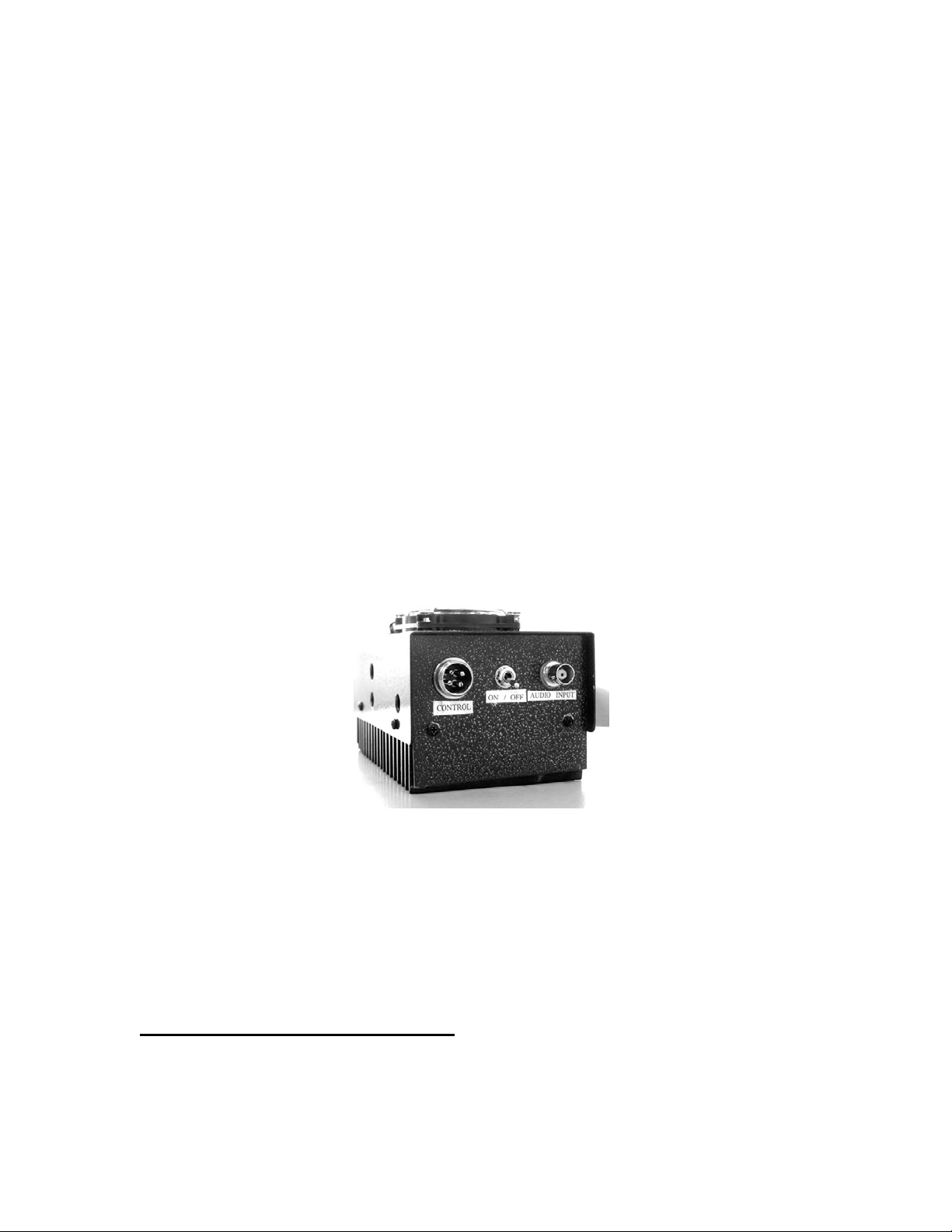
The front side of the OM-1 has an on-off switch, a BNC connector, and a 4 pin
microphone connector. The OM-1 is not designed for voice communication! The 4 pin
connector allows one to use a computer controlled relay system to automatically turn the
transmitter function on and off.
The OM-1 is extremely simple to use, there two primary rule to remember:
1. The OM-1 is extremely sensitive to the input square wave power level! Excessive
voltage and current can destroy the audio amplifier chip! Do Not !!! attempt to
operate your OM-1 until after reading all instructions and setting input voltage
from your frequency generator to an absolute minimum.
2. Do not operate (transmit) your OM-1 without being connected to some sort of
load!
Preparing The OM-1 For Use
1. Make certain all power switches are in the off position. This includes the power
supply , the OM-1 transmitter, and the frequency generator.
2. Most frequency generators will lack any ability to computer control the OM-1.
Use a BNC cable to connect your frequency generator output to the input BNC
connector on the OM-1. Make certain power output is set to a minimum! Many
frequency generators will have a –db button or buttons . Push ALL of these in.
3. Connect the power wire with the fuse in it, found on the back side of the OM-1,
to the positive side of a 13.8 volt, 5 ampere or greater , power supply.
4. Connect the negative power wire on the back of the OM-1 to the negative side of
a 13.8 volt power supply.
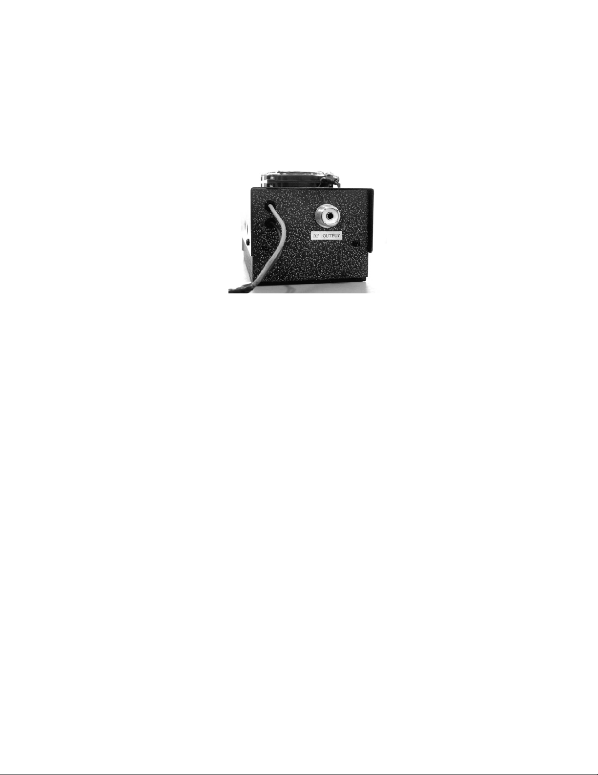
5. Connect a coaxial cable to the SO-239 connector on the back side of the OM-1.
The other end of the cable should be connected to an antenna tuner or some sort
of pre balanced load, such as an antenna, dummy load, laser plasma tube etc. .
6. Turn on the power supply, the fan should start running on the top of the OM-1.
Turn on transmitter with a connected appropriate load . It is important that SWR
values be balanced. The OM-1 has been tested for prolonged operational times
with poor SWR’s . It has survived 30 minutes operation with SWR’s of 3 to 3.5.
If your antenna or load is not balanced to the OM-1, you will risk damaging the
OM-1. It is highly suggested that you balance SWR using an impedance matcher
of some sort ( antenna tuner) between the OM-1 and it’s load.
7. Turn on frequency generator set to about 3000 Hz . Slowly start increasing output
power level of your frequency generator until power level of the OM-1
maximizes. This power level is best seen on the SWR meter of an antenna tuner.
Continue to increase audio level until power output of transmitter drops. Once a
drop in power level is noted, quickly reduce audio output level from the frequency
generator until power output of the OM-1 once again maximizes. Note where this
output is, then decrease output level of the frequency generator till power starts to
drop. Note where this level is. Operate the OM-1 at an output level half way
between these maximum and minimum audio output settings. Do not drive the
OM-1 on the edge of maximum audio input voltage!
8. In most applications the output level of a frequency generator can be set at
between 0.3 and 0.5 volts P-P using an oscilloscope. Some frequency generators
do not have much current output and these may take from 3 to 7 volts p-p to
maximize output of the OM-1.

9. 0.4 volts output from a frequency generator is very low! This can easily be
exceeded if one is not careful. Once set the OM-1 should provide years of trouble
free operation.
10. It is advised that only one input be used with the OM-1 at a time. That is use
either the BNC input or the 4 pin input, do not have both connected to separate
frequency generators at the same time.
OM-1 Maintenance:
The OM-1 should be virtually maintenance free. Keep obstructions away from the fan
and vent holes on the sides of the OM-1. Adequate air circulation is necessary for the
longevity of the OM-1’s electronic components. Do not allow liquids to fall onto the
OM-1.
Interference:
Interference from the RF emissions from the OM-1 should be minimal, and affect only
electronic equipment within a few feet of the device. As such, keep the OM-1 separated
from other electronic equipment by at least one meter distance.
Should it become necessary to further limit RF emissions, the following may be tried. RF
emission may be limited by using a RF chokes on the AC line cord of the power supply,
the input and output ends of the BNC cable from the frequency generator, and keeping all
RF carrying wires to the item being driven by the OM-1 as short as possible.
Specifications:
Carrier Frequency – 27.125 MHz
Un modulated Carrier output power – Typical 3.8 W
Modulated Output power – 32 watts typical PEP @ 5000 Hz into a 50 ohm load.
Power Supply Required 13.8VDC @ 5 amps
Duty cycle 100%
Compliance Information:
Name and Model # OM-1
FCC ID: RKYOM-1
This Device Complies with Part 18 of the FCC Rules
Plasma Sonics Ltd. Co.
8005 Marble Ave. NE
Albuquerque, NM 87110
505-268-4272

 Loading...