

Page 1
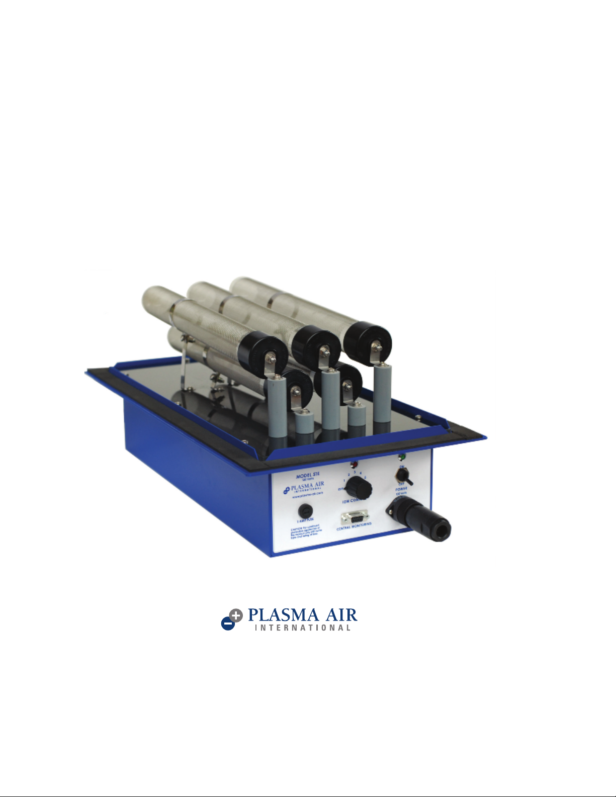
INSTALLATION, OPERATION
& MAINTENANCE MANUAL
PLASMA AIR
MODEL 50 SERIES
(MODELS 51E, 51F, 52E, 52F)
REV 02/2018
Page 2
INTRODUCTION
Plasma Air models 51E, 51F, 52E, and 52F air ion generators are 5 tube industrial quality units intended for installation in
air handling units or in duct systems for commercial and industrial facilities.
This ionization equipment is effective in reducing harmful pollutants and odors by introducing positive and negative
ions in the system airflow. The number of units and the size of th
the system and the severity of the pollution problem. Model number nomenclature is further specified as follows:
5XY: X = 1 (120 Volts) or 2 (230 Volts)
Y = E (E-tubes) or F (F-tubes)
For example, a 51F is a 120 Volt, 5 tube unit with F-tubes
e ionization tubes are dependent upon the airflow in
MECHANICAL INSTALLATION INSTRUCTIONS
Warning: To reduce the risk of fire, this unit should not be installed downstream from a humidifier or exposed to other
sources of moisture.
Caution: This product is suitable for mounting into duct of metallic construction only. Installation must be such that the
structural integrity of the ducting is not compromised.
1) Carefully remove the equipment from its shipping carton. Ensure that no damage occurred to any of the components.
2) Install the ionizing tubes using the sup
contact with the tube sock. The top middle tube should be installed first.
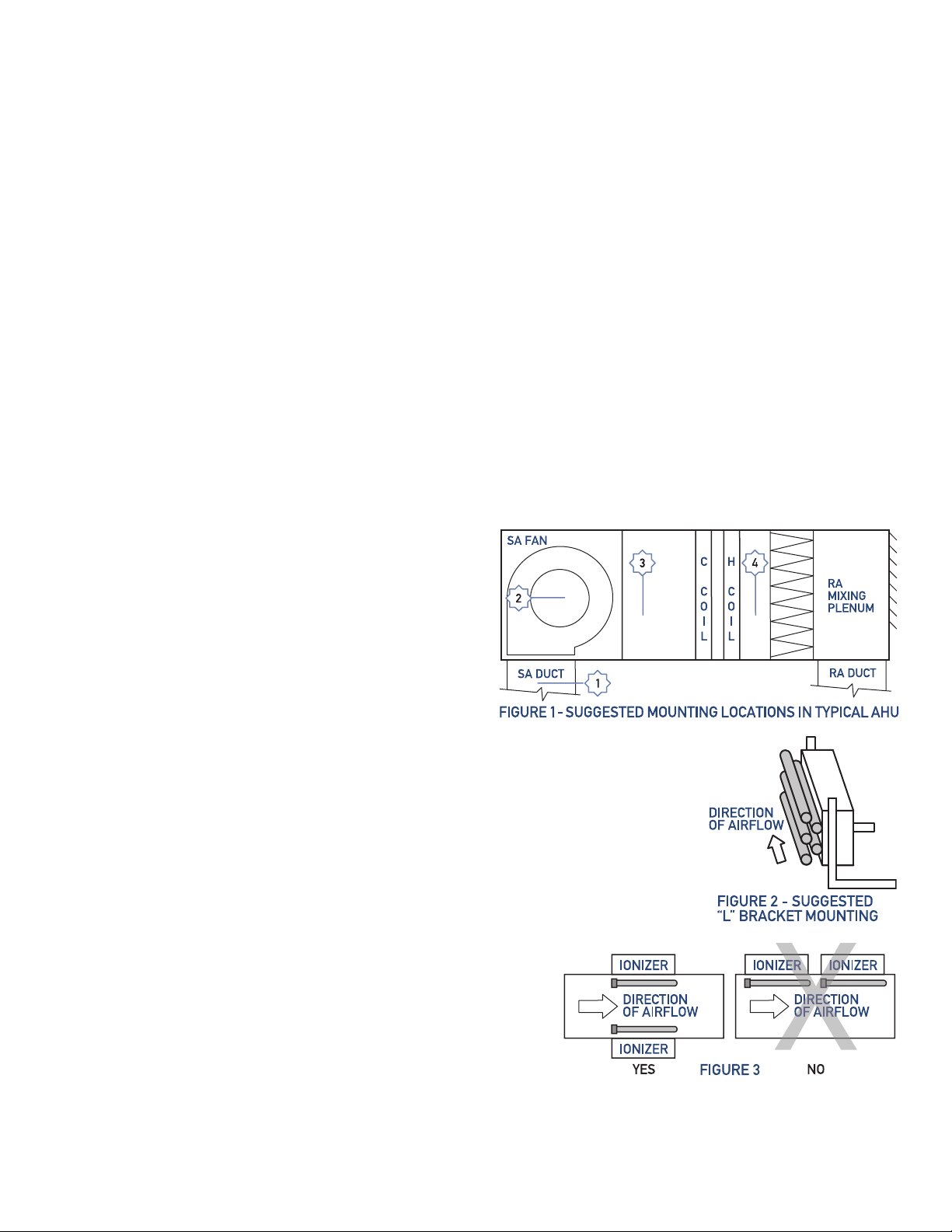
3) The units can either be installed inside an air handling unit or in the supply air ductwork. See figure 1 for acceptable
mounting locations.
Mounting location notes:
• Ensure sufficient airflow over the ionization tubes.
• Do not mount the units in the
the system filter.
• Do not install immediately downstream of a humidifier.
• Allow sufficient space immediately downstream of the
cooling coil to avoid moisture carryover.
• Disconnect any Electronic Air Cleaner.
To mount the units inside an air handling unit, use “L”
a)
shaped brackets that are secured to the walls or floor of the AHU with sheet metal
screws. The units sho
tubes, after the system filter, and not immediately downstream of the cooling coil to
avoid any moisture carryover. See figure 2
b)To mount the units in a duct, make a 19.5” X 9” rectangular cutout in the duct for a
50E and a 26” X 9” cutout in the duct for a 50F. Pre-drill mounting screw holes using
the unit as a template. The
duct and the equipment.
4) It is preferable, although not mandatory, to install the units with the tubes parallel to
the airflow. See figure 2
5)
If multiple units are installed on the same duct, the units need to be
installed around the perimeter of the duct so that ionized air from
one unit does not pass over a second ionizing unit. See f
6) Units should be installed to allow access to the ionization level
adjustment knob and for general maintenance.The unitsshould
not be installed behind a suspended floor/ceiling or a structural
wall, ceiling or floor.
return air duct or before
uld be installed so there is sufficient airflow across the ionization
units have a flange gasket that forms a seal between the
plied friction nuts. Tighten the 4mm grounding clamp screws to ensure good
igure 3
PLASMA AIR INTERNATIONAL 35 MELROSE PLACE STAMFORD, CT 06902 203-662-0800 [email protected] www.plasma-air.com PLASMA AIR INTERNATIONAL 35 MELROSE PLACE STAMFORD, CT 06902 203-662-0800 info@plasma-air.com www.plasma-air.com
Page 3
ELECTRICAL INSTALLATION INSTRUCTIONS
Warning: The secondary voltage to the ionization tubes can be 2,900 Volts AC. Do not connect to power before the installation
is complete. Always disconnect power to the unit before handling any of the unit components.
1) The power required is 10 watts per ionizing tube. The typical 50 unit draws about 50 watts. The power source should not
be protected by a breake
2) The Model 50 is available in two primary voltage models, nominally 120 volts AC or 230 volts AC. The units may be used
on 50 cycle or 60 cycle frequencies. Verify that the Model 50’s voltage is the same as the available voltage by checking
the UL label on the unit.
3) The unit should be powered when the system supply fan is energized. This can be accomplished by any of the following
methods:
a.On systems with single speed supply fans, the fan power supply can be used.
b.Use an airflow switch in series with the unit’s power supply.
c. Install a relay off the 24 volt fan control circuitry and wire the unit’s power wiring through the NO contacts.
d.Install a supply fan power current sensing relay and wire the unit’s power wiring through the NO contacts.
4) A field-installed junct
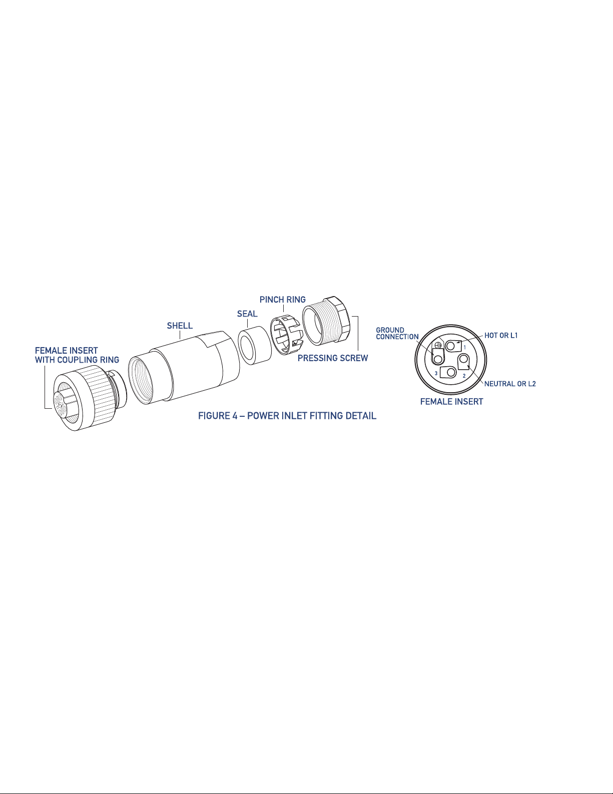
installed between the junction box and the power fitting shown in figure 4.
r exceeding 20 amps.
ion box should be installed within 4 feet of the unit. 3/8 inch flexible metal conduit or BX should be
5) See figure 4. Step by step instructions for inserting power wiring into power inlet fitting:
Step 1) Trim the protective steel armor of the BX cable exposing between 1” and 1¼“ of the internal wires.
Step 2) Strip the wire
Step 3) Unscrew the Shell assembly from the Female Insert by pushing the Coupling Ring towards the Shell assembly
and unscrewing counterclockwise.
Step 4) Unscrew the Pressing Screw counterclockwise exposing the Pinch Ring and rubber Seal.
Step 5) Slide the Pressing Screw, Pinch Ring, Seal, and Shell over the BX cable, insuring that all pieces are in the right
order and direction
Step 6) Insert the Hot or L1 (black) wire into the No. 1 hole on the Female Insert fitting. Insert the Neutral or L2 (white)
wire into the No. 2 hole and the Ground wire into the ground hole. NOTE: Inserting all three wires simultaneously
makes the assembly process easier. Tighten the set screws securely.
Step 7) Slide the Shell fitting towards the Female Insert fitting and screw togeth
Step 8) Ensure that the rubber Seal is sitting snugly inside the large end of the Pinch Ring.
Step 9) Slide the Seal and Pinch Ring assembly and the Pressing Screw towards the Shell fitting.
Step 10) Insert the Seal and Pinch Ring assembly into the Shell fitting and screw the Pressing Screw into the Shell fitting
securing the BX cable tightly into the Shell assembly.
Step 11) Plug the comple
to join the two fittings. The Female Insert will only fit onto the male fitting one way.
s exposing 3/8” copper.
as shown above.
er clockwise.
ted assembly into the male fitting on the ionization unit and screw the Coupling Ring clockwise
Page 4

OPERATION
1) Turn the unit on/off switch to the “on” position. The green light over the switch will illuminate if power is available to the unit.
2) The ionization adjustment knob is a six-position switch that can be used to adjust the level of ionization. When the knob is in
the “0” position, no power is being applied to the ionization tubes. The red light over the knob will be off. Rotating the kno
from “0” through “5” increases the ionization output and the red light illuminates.
3) The ionization level is set by the installing contractor and does not require adjustment on a regular basis. The resulting
ionization level in the treated space should fall between 500 and 1500 ions/cm3. An ion meter can be used to measure the
ionization level. Alternatively, the ionization level can be adjust
quality result is achieved. An Ion Meter can be purchased from Plasma Air or your local distributor, www.plasma-air.com.
ed by the contractor or the end user until the desired air
b
MAINTENANCE
Warning: The secondary voltage to the ionizing tubes can be 2,900 Volts AC. Always disconnect power to the unit and switch
the power to the “off” position before performing any maintenance.
1) Depending on the s
17,600 hours of service and should be replaced at that interval. Contact your local Plasma Air Distributor/Dealer to purchase
replacement tubes when necessary, www.plasma-air.com.
2) Plasma Air equipment requires very little maintenance, especially when the air in the system is properly filtered.
with heavily polluted air, the ionization tubes should be inspected every six months. The tubes should be cleaned, if necessary,
at the six-month inspection. Always wear gloves for personal protection when handling the ionization tubes. To clean the tubes:
a) Remove the tubes from the unit.
b) Remove the wire mesh “sock” from the outside of the tubes. Wash the sock in clean soapy water. D
Cleantheoutsideglassofthe tube withclean soapy water or commercially availableglasscleaner. Dry thetubethoroughly.
c)
d) Replace the sock and reinstall the tubes. Install the top middle tube first.
everity of the pollutant, the upstream filtration and the maintenance schedule, the tubes are rated for
On projects
ry the sock thoroughly.
REMOTE MONITORING
1) The unit is equipped with an alarm circuit that will open on loss of power. This circuit can be used to initiate a local alarm
or be tied into a building automation system (BAS).
2) The circuit is rated for 10 amps at 230V AC.
3) A nine conductor cable is provided with the unit. The black and white wires should be used to connect to the building’s
monitoring system.
TROUBLESHOOTING
If the unit is not working, check in order that:
1) The power switch is in the “on” position and that the green light illuminates.
2) The 1.0 Amp, glass cartridge fuse is not blown. The fuses are
electrical supply store.
3) If the unit fuse is blown, remove all tubes and replace the fuse. Turn on power to the unit. If the fuse blows again, return
the unit to the distributor for factory service.
4) If the fuse does not blow, the most likely problem is a cracked tube. Carefully inspect the tubes for cracks. Although rare,
cracks are usually
5) If the tube has been subjected to high temperatures, above 140º F, there is a possibility of a pin hole. These are difficult
to spot, but can cause shorting of the tube. Install tubes into the unit one at a time, powering the unit after each tube
installation. If the fuse blows, the last tube installed is defective and requires replacement.
6) If there seems to
year old, replace them.
found at the capped end of the tube.
be a loss of effectiveness, check the tubes and clean them if necessary. If the tubes are more than a
5mm x 20mm rated at 250 volts and are available at any
PLASMA AIR INTERNATIONAL 35 MELROSE PLACE STAMFORD, CT 06902
© 2018 Al l rights reserved
 Loading...