

Plasma Air 50 Series, 51E, 52E, 52F, 51F Installation, Operation & Maintenance Manual
INSTALLATION, OPERATION
& MAINTENANCE MANUAL
PLASMA AIR
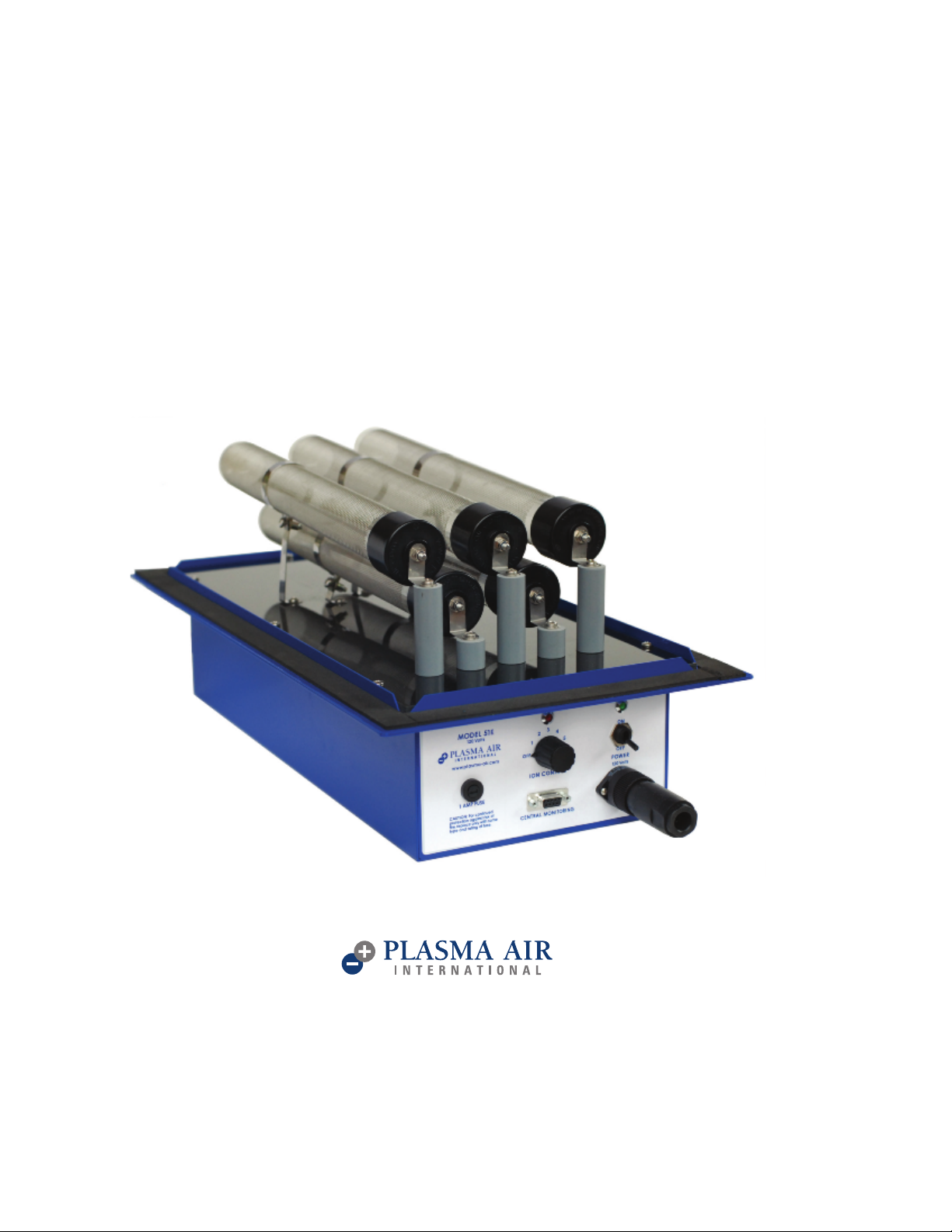
MODEL 50 SERIES
(MODELS 51E, 51F, 52E, 52F)
REV 02/2018
INTRODUCTION
Plasma Air models 51E, 51F, 52E, and 52F air ion generators are 5 tube industrial quality units intended for installation in
air handling units or in duct systems for commercial and industrial facilities.
This ionization equipment is effective in reducing harmful pollutants and odors by introducing positive and negative
ions in the system airflow. The number of units and the size of th
the system and the severity of the pollution problem. Model number nomenclature is further specified as follows:
5XY: X = 1 (120 Volts) or 2 (230 Volts)
Y = E (E-tubes) or F (F-tubes)
For example, a 51F is a 120 Volt, 5 tube unit with F-tubes
e ionization tubes are dependent upon the airflow in
MECHANICAL INSTALLATION INSTRUCTIONS
Warning: To reduce the risk of fire, this unit should not be installed downstream from a humidifier or exposed to other
sources of moisture.
Caution: This product is suitable for mounting into duct of metallic construction only. Installation must be such that the
structural integrity of the ducting is not compromised.
1) Carefully remove the equipment from its shipping carton. Ensure that no damage occurred to any of the components.
2) Install the ionizing tubes using the sup
contact with the tube sock. The top middle tube should be installed first.
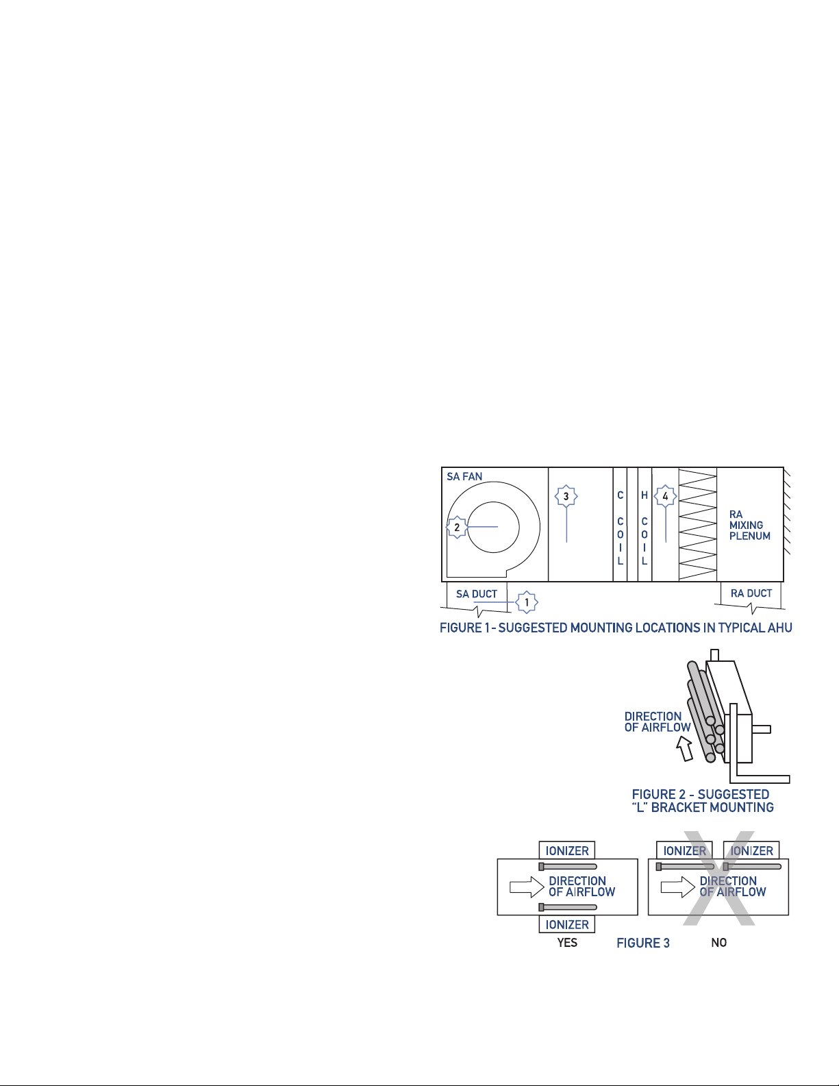
3) The units can either be installed inside an air handling unit or in the supply air ductwork. See figure 1 for acceptable
mounting locations.
Mounting location notes:
• Ensure sufficient airflow over the ionization tubes.
• Do not mount the units in the
the system filter.
• Do not install immediately downstream of a humidifier.
• Allow sufficient space immediately downstream of the
cooling coil to avoid moisture carryover.
• Disconnect any Electronic Air Cleaner.
To mount the units inside an air handling unit, use “L”
a)
shaped brackets that are secured to the walls or floor of the AHU with sheet metal
screws. The units sho
tubes, after the system filter, and not immediately downstream of the cooling coil to
avoid any moisture carryover. See figure 2
b)To mount the units in a duct, make a 19.5” X 9” rectangular cutout in the duct for a
50E and a 26” X 9” cutout in the duct for a 50F. Pre-drill mounting screw holes using
the unit as a template. The
duct and the equipment.
4) It is preferable, although not mandatory, to install the units with the tubes parallel to
the airflow. See figure 2
5)
If multiple units are installed on the same duct, the units need to be
installed around the perimeter of the duct so that ionized air from
one unit does not pass over a second ionizing unit. See f
6) Units should be installed to allow access to the ionization level
adjustment knob and for general maintenance.The unitsshould
not be installed behind a suspended floor/ceiling or a structural
wall, ceiling or floor.
return air duct or before
uld be installed so there is sufficient airflow across the ionization
units have a flange gasket that forms a seal between the
plied friction nuts. Tighten the 4mm grounding clamp screws to ensure good
igure 3
PLASMA AIR INTERNATIONAL 35 MELROSE PLACE STAMFORD, CT 06902 203-662-0800 info@plasma-air.com www.plasma-air.com PLASMA AIR INTERNATIONAL 35 MELROSE PLACE STAMFORD, CT 06902 203-662-0800 info@plasma-air.com www.plasma-air.com
 Loading...