

Page 1
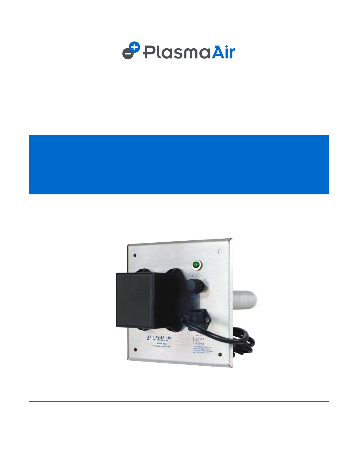
INSTALLATION, OPERATION
& MAINTENANCE MANUAL
Plasma Air
100 SERIES
(MODELS 101C, 101D, 101E, 102C, 102D, 102E , 103C, 103D, 103E)
REV 08/2019
www.plasma-air.com
Page 2
INTRODUCTION
The Plasma Air 100 Series ion generator is a one-tube commercial quality unit intended for installation in air handling
units (AHU), furnaces, or duct systems for residential and commercial applications.
This ionization equipment is effective in reducing harmful pollutants and odors by introducing positive and negative
ions into the system airow. The number of units and the size of the ionization tubes are dependent on the airow in
the system and the severity of the pollution problem. See chart on the back of this manual for selection criteria.
MECHANICAL INSTALLATION INSTRUCTIONS
WARNING: To reduce the risk of re, this unit should not be installed downstream of a humidier
or exposed to other sources of moisture.
CAUTION: This product is suitable for mounting into duct of metallic construction only. Installation
must be such that the structural integrity of the ducting is not compromised.
Mount units to allow access to the ionization level adjustment knob and for general maintenance. This product shall
not be installed behind a suspended oor/ceiling or a structural wall, ceiling, or oor.
This product should not be mounted in a location where the air temperature exceeds 140° F. This usually means that
it should not be installed at the outlet of a gas or oil red furnace.
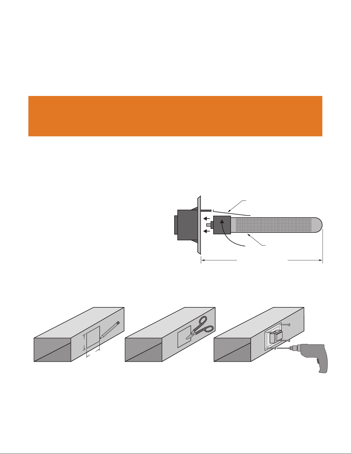
1. Screw the ionization tube using the end cap into the back of the transformer while gently holding the grounding clip
away from the tube.
2. For residential installations, the preferred location
is in the supply air duct leaving the AHU. Be sure
to pick a location before any branch duct take-offs.
Verify that there is sufcient duct depth to allow
clearance for the tube – see Figure 1.
To mount the units in a duct:
a. Trace a 5½" by 5½" square on the surface of
the duct onto which you are mounting the 100
Series. The units have a ange gasket that forms
a seal between the duct and the mounting plate.
b. Cut out the traced portion of the duct using snips
or sheet metal shears.
c. Screw the 100 Series ionizer onto the duct using
sheet metal screws.
FIGURE 1 – MODEL 100 AND IONIZATION TUBE
GROUNDING CLIP
IONIZATION TUBE
TUBE CLEARANCE
C=7½", D=10½", E=14½"
5½"
a. b. c.
5½ "
3. If the unit cannot be installed in the preferred location due to space or temperature limitations, see Figure 2 for
alternate locations. Units can be installed using “L” shaped brackets available from many hardware suppliers.
4. For commercial applications, the units can be mounted in the supply air duct as long as these ducts are easily
accessible for tube replacement or other service. Units are sometimes mounted inside a roof top AHU using “L”
shaped brackets available at many hardware suppliers. Be sure to select a location within the air handling unit
where there is good air ow. One such location is immediately next to the fan inlet.
Page 3
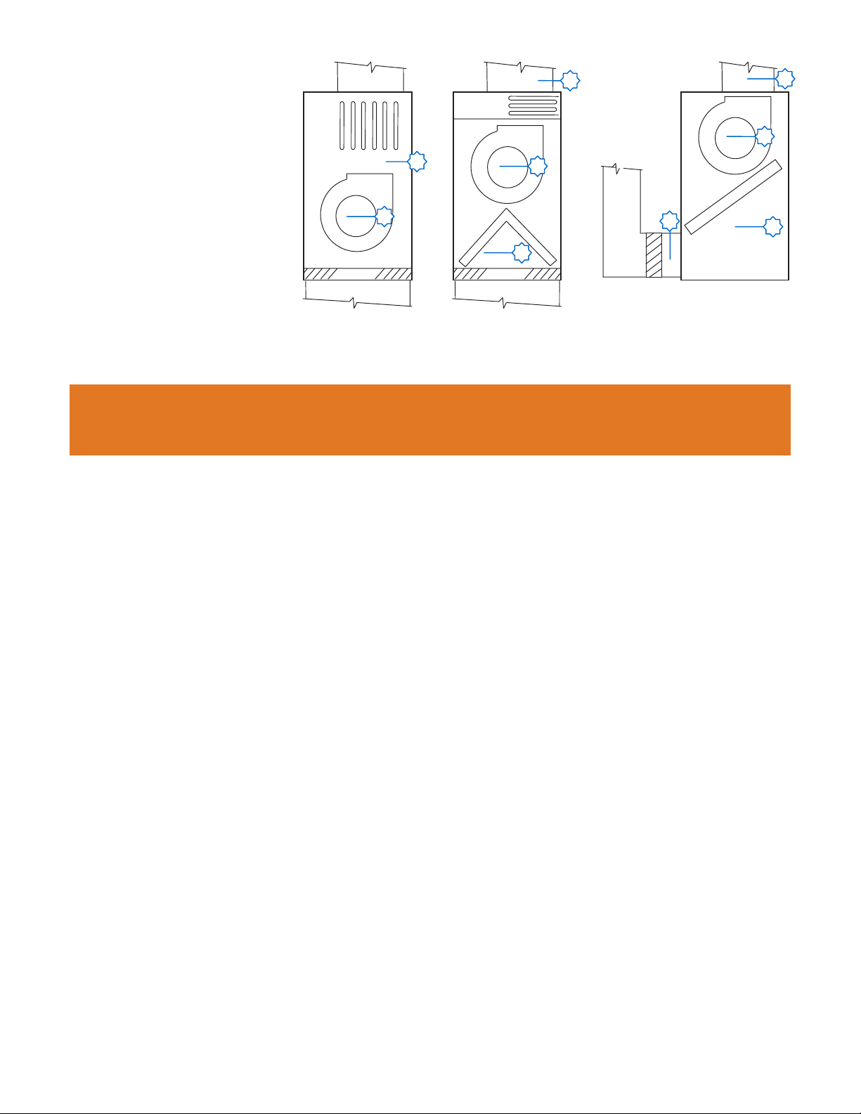
Mounting location notes:
• Ensure sufcient airow
over the ionization tubes.
• Do not mount the units
before the system lter.
• Do not mount downstream
of a gas or oil red furnace.
• Avoid locations where
SA DUCT SA DUCT SA DUCT
ELECTRIC
OR
HW HEAT
SA FAN
GAS MANIFOLD
SA FAN
COIL
RA
DUCT
SA FAN
COIL
moisture may be
present like immediately
downstream of a cooling
coil.
FILTER
RA DUCT RA DUCT
FIGURE 2 – SUGGESTED MOUNTING LOCATIONS IN A TYPICAL AHU OR FURNACE
FILTER
FILTER
ELECTRICAL INSTALLATION INSTRUCTIONS
WARNING: The secondary voltage at the ionizing tubes can be 2,900 Volts AC. Do not connect to
power before the installation is complete. Always disconnect power to the unit before handling any
of the unit components.
To reduce the risk of electric shock, this equipment has a grounding type plug that has a third (grounding) pin. This
plug will only t into a grounding type power outlet. If the plug does not t into the outlet, contact qualied personnel
to install the proper outlet.
1. The 100 Series is available in three primary voltage models, nominally 120 volts AC (model 101) or 230 volts AC
(model 102), or 24 volts AC (model 103). The units may be used on 50 cycle or 60 cycle frequencies. Verify that the
model’s voltage is the same as the available voltage by checking the ionizer's UL label.
2. The 100 Series draws up to 8 Watts. The power source should not be protected by a breaker exceeding 20 amps.
3. The unit should be powered when the system supply fan is energized. This can be accomplished by any of the
following methods:
• On systems with single speed supply fans, the fan power supply can be used.
• Use a pressure switch in series with the ionizer's power supply.
• Install a relay off the 24 volt fan control circuitry and wire the ionizer’s power through the NO contacts.
• Install a current sensing relay on supply fan power wiring and then wire the ionizer’s power through the NO
contacts.
• Wire into the “EC” (Electronic Air Cleaner) contacts oftentimes provided on the AHU.
• On systems where the above fan interlocking options are not available, contact your distributor/dealer
or Plasma Air directly for an AFS-MF-JB unit. This product is a mounting frame with an integral pressure
differential switch that allows the unit to be hard wired in the eld via integral junction box.
OPERATION
The ionization adjustment knob is a six-position switch that is used to turn the unit on and adjust the level of ionization.
1. When the knob is in the “0” position, no power is being applied to the ionization tubes and the green light is off.
Rotating the knob from “0” through “5” increases the ionization output and will illuminate the green light.
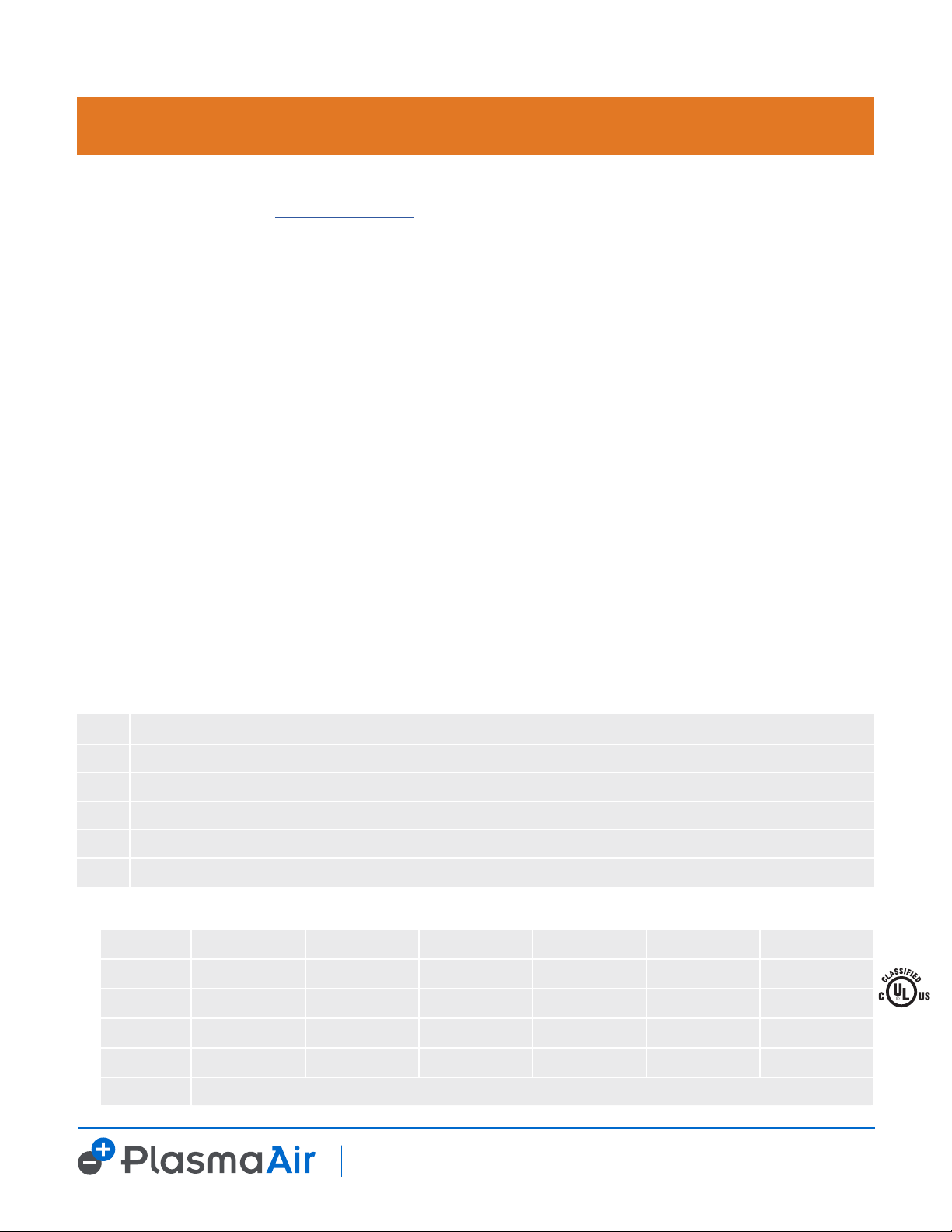
2. The ionization level is set by the installing contractor and does not require adjustment on a regular basis. A guide is
provided on the back cover of this manual to set the ionization level based on the Pollutant Load Factor.
3. The benet of the ionization system is only realized when the supply fan is running. So to achieve improved air
quality, run the fan continuously or use an IAQ type thermostat which will cycle the fan once an hour at specied
times of the day.
Page 4
MAINTENANCE
WARNING: The secondary voltage to the ionizing tubes can be 2,900 Volts AC. Always disconnect
power to the unit and switch the power to the “off” position before performing any maintenance.
Depending on the severity of the pollutant, the upstream ltration and the maintenance schedule, the tubes are rated
for 17,600 hours of service and should be replaced at that interval. Contact your local Plasma Air Distributor to
purchase replacement tubes, www.plasma-air.com.
TROUBLESHOOTING
If the unit is not working, check in the following order that:
1. The ionization adjustment knob is in between “1” and “5” and that the green light illuminates.
2. The 0.5 amp, glass cartridge fuse is not blown. The fuse is located in the power inlet tting. The fuses are 5mm ×
20mm rated at 250 volts and are available at any electrical supply store.
3. If the unit fuse is blown, remove the tube and replace the fuse. Turn on power to the unit. If the fuse blows again,
return the unit to the distributor for factory service.
4. If the fuse does not blow, the most likely problem is a defective tube. Carefully inspect the tube for cracks.
Although rare, cracks can occur at the capped end of the tube.
5. If the tube has been subjected to high temperatures, above 140º F, there is a possibility of a pin hole defect. These
are difcult to spot, but can cause shorting of the tube. Install the tube into the unit and power the unit. If the fuse
blows, the tube is defective and requires replacement.
6. If there seems to be a loss of effectiveness, check the tubes and clean them if necessary. If the tubes are more than
two years old, replace them.
PRODUCT SELECTION
Selecting the proper ionization equipment is important for achieving all the benets from the ionization system. In
commercial or industrial projects, pollutants such as airborne particles from smoke, dust, spores; VOCs from cleaning
supplies, glues, paints, or other chemicals; odors from locker rooms, cooking, nursing homes, industrial processes;
and even health related concerns from mold, bacteria, and viruses all contribute to poor indoor air quality. The
information below will guide you through the process.
POLLUTANT LOAD FACTOR
A Normal residential, ofce, or classroom space - low pollutant levels
B Day care center, nursing home, food processing facility, restaurant - medium pollutant levels
C Animal hospital, casinos, light manufacturing, smoking areas, nail/beauty salons - heavy pollutant levels
D Industrial facility, heavy manufacturing, or garbage room - very heavy pollutant levels
E Heavy pollution or odors typical of a waste water treatment facility
SQUARE FOOTAGE SERVED BY AIR HANDLER
1,000 2,000 3,000 5,000 10,000 20,000
A
B
C
D
(
(
(
(1)
1) 100C
1) 100D
1) 100E
200E
(1)
(1)
(1)
(1)
100D
100E
200E
50E
(1)
(1)
(1)
(1)
100E
200E
50E
50F
(1)
(1)
(1)
(2)
200E
50E
50F
50F
(1)
(2)
(2)
(4)
50F
50E
50F
50F
(2)
(3)
(4)
(8)
50F
50F
50F
50F
POLLUTANT LOAD FACTOR
E
*Consult Plasma Air Engineering Department for Engineering Support
PLASMA AIR 35 MELROSE PLACE, STAMFORD, CT 06902
phone 203-662-0800 fax 203-662-0808 www.plasma-air.com [email protected]
© 2019 All rights reserved
PA-US-IOM-006
 Loading...