


EN
Digital Radiography System
user's manual
10019763_11


TABLE OF CONTENTS
1 INTRODUCTION ..............................................................................................1
2 SYMBOLS ........................................................................................................2
3 RELATED MANUALS ......................................................................................2
4 SAFETY PRECAUTIONS ................................................................................3
5 SYSTEM REQUIREMENTS .............................................................................4
6 PLANMECA PROSENSOR CONTROLBOX INDICATOR LIGHT ..................5
7 BEFORE EXPOSURE ......................................................................................6
7.1 Positioning the patient .................................................................................................... 6
7.2 Positioning the sensor .................................................................................................... 6
7.3 Selecting exposure values ............................................................................................. 8
8 CAPTURING INTRAORAL IMAGES .............................................................10
8.1 Capturing single intraoral images ................................................................................ 10
8.2 Capturing images into a study template ....................................................................... 12
9 IMAGE QUALITY CONTROL .........................................................................14
9.1 Quality check using SMPTE test pattern ..................................................................... 14
10 USING THE SENSOR HOLDERS ..................................................................14
11 CLEANING .....................................................................................................15
11.1 Surfaces ....................................................................................................................... 15
11.2 Sensors and cables ..................................................................................................... 15
11.3 Sensor holders .............................................................................................................16
11.4 Planmeca ProSensor ControlBox ................................................................................ 16
12 DISPOSAL OF PLANMECA PROSENSOR ..................................................17
13 TECHNICAL SPECIFICATIONS .................................................................... 18
APPENDIX A: EXPOSURE VALUES FOR PLANMECA PROX ...................20
A.1 Default exposure values .............................................................................................. 20
A.2 Preprogrammed settings values .................................................................................. 21
User’s Manual
Planmeca ProSensor 1

TABLE OF CONTENTS
The manufacturer, assembler, and importer are responsible for the safety,
reliability and performance of the unit only if:
- installation, calibration, modification and repairs are carried out by qualified
authorized personnel
- electrical installations are carried out according to the appropriate
requirements such as IEC 60364
- equipment is used according to the operating instructions
Planmeca pursues a policy of continual product development. Although every
effort is made to produce up-to-date product documentation this publication
should not be regarded as an infallible guide to current specifications. We
reserve the right to make changes without prior notice.
COPYRIGHT PLANMECA
Publication number 10019763 Revision 11
Released 21 November 2013
2 Planmeca ProSensor
User’s Manual

1 INTRODUCTION
INTRODUCTION
This manual describes how to use and install the
Planmeca ProSensor sensor that is intended to be used
for capturing digital intraoral x-ray images from patient’s
jaw, teeth, gums, roots and root canals by trained dental
care professionals.
Please read this manual carefully before using the
system.
Planmeca ProSensor automatically triggers and captures
images to the start and end of the x-ray radiation so that
any intraoral x-ray unit supporting exposure times and
cones listed in tables of chapter “Exposure values for
Planmeca ProSensor” can be used.
The Planmeca Romexis imaging software or third party
software stating compatibility with Planmeca ProSensor
or software stating compatibility through TWAIN can be
used for image capturing.
Planmeca ProSensor is connected to a computer using
Ethernet or USB interface and it supports Windows and
MAC operating systems, see details in section
“TECHNICAL SPECIFICATIONS” on page 18.
This manual is valid for following software revisions:
• Planmeca ProSensor Ethernet software version 2.1.0.R
or later
• Planmeca ProSensor USB software version 2.2.1.R or
later
• Didapi software version 4.8.1or later.
User’s Manual
Planmeca ProSensor 1

SYMBOLS
2 SYMBOLS
Type BF equipment (Standard IEC 60601-1).
Attention, consult accompanying documents
(Standard IEC 60601-1).
The use of accessory equipment not complying with the
equivalent requirements of this equipment may lead to a
reduced level of safety of the resulting system.
Consideration relating to the choice shall include:
• use of the accessory in the Patient Vicinity
• evidence that the safety certification of the accessory has
been performed in accordance to appropriate IEC60601
and/or IEC60601-1-1 harmonized national standard.
ETL CLASSIFIED
3143029
3 RELATED MANUALS
Planmeca ProSensor is ETL classified and conforms to
ANSI/AAMI ES60601-1 and is certified to CAN/CSA
C22.2 No. 60601.1:08.
Separate collection for electrical and electronic equipment
according to Directive 2002/96/EC (WEEE)
This manual should be used in conjunction with following
manuals:
• Planmeca ProX User’s manual (10029963)
• Planmeca Romexis User’s manual (10014593)
2 Planmeca ProSensor
User’s Manual

4 SAFETY PRECAUTIONS
NOTE The system should be operated by qualified
NOTE EMC requirements have to be considered, and the
CAUTION Handle the Planmeca ProSensor according
SAFETY PRECAUTIONS
personnel only.
equipment must be installed and put into service
according to the specific EMC information provided
in the accompanying documents.
to the instructions given in this manual. Do
not pinch the sensor or the cable. Do not to
drop the sensor or pull strongly the sensor
cable. Never cut, nick or sharply bend the
sensor cable. Always advise the patient not
to bite the sensor or the cable. The
Planmeca limited warranty does not cover
damage which is due to misuse, e.g.
dropping the sensor, neglect, or any cause
other than ordinary application.
CAUTION Do not let the sensor cable run along the
floor. Protect the cable from rolling over it
with a chair or walking over it.
CAUTION Do not store or use the Planmeca Sensor
near (3m or 10 ft) an electrosurgical knife.
CAUTION Do not unnecessarily touch the connector
pins to keep them clean.
User’s Manual
Planmeca ProSensor 3

SYSTEM REQUIREMENTS
5 SYSTEM REQUIREMENTS
NOTE The PC and other equipment connected to the system
must be:
• approved by local authorities: e.g. IEC-approved (CE
marked), UL / CSA approved
• located outside the patient area (more than 2m (79 in.)
from the X-ray unit)
• protectively earthed.
NOTE The connection of additional equipment to a multiple
portable socket-outlet must only be possible by using
a tool or be supplied via separating transformer.
NOTE The multiple portable socket-outlets shall not be
placed on the floor.
NOTE Make sure that the system is protected with fire wall
and up-to-date anti-virus software. If possible, isolate
the system from office network.
NOTE For latest up-to-date system requirements see also
Planmeca website > Software > System requirements
Table 1. Planmeca Romexis system requirements
Planmeca Romexis
client work station
Processor Intel Core 2 Duo 2 GHz or better Intel Core 2 Duo 3GHz or better
RAM 3 GB 3 GB minimum
Hard disk space 80 GB 2 x 500 GB (RAID/mirroring)
Graphics card Any integrated or dedicated Any
USB port USB port 2.0 USB port 2.0
Monitor 1280 x 1024 1280 x 1024
Peripherals CD-ROM drive CD-ROM drive
Backup medium None necessary DAT or equivalent
Windows XP Pro (32 bit)
Windows Vista Pro (32 or 64 bit)
Operating system
Windows 7 Pro (32 or 64 bit)
Windows 8 Pro (32 or 64 bit)
Mac OS X (Intel)*
Planmeca Romexis
database server
Windows XP Pro (32 bit)
Windows 2003 Server (32 or 64)
Windows 2008 Server (32 or 64)
Windows Vista Pro (32 or 64)
Windows 7 Pro (32 or 64)
Windows 8 Pro (32 or 64)
Mac OS X (Intel)
Other
4 Planmeca ProSensor
Java platform (Java Virtual
Machine 1.6)
Java platform (Java Virtual
Machine 1.6)
User’s Manual
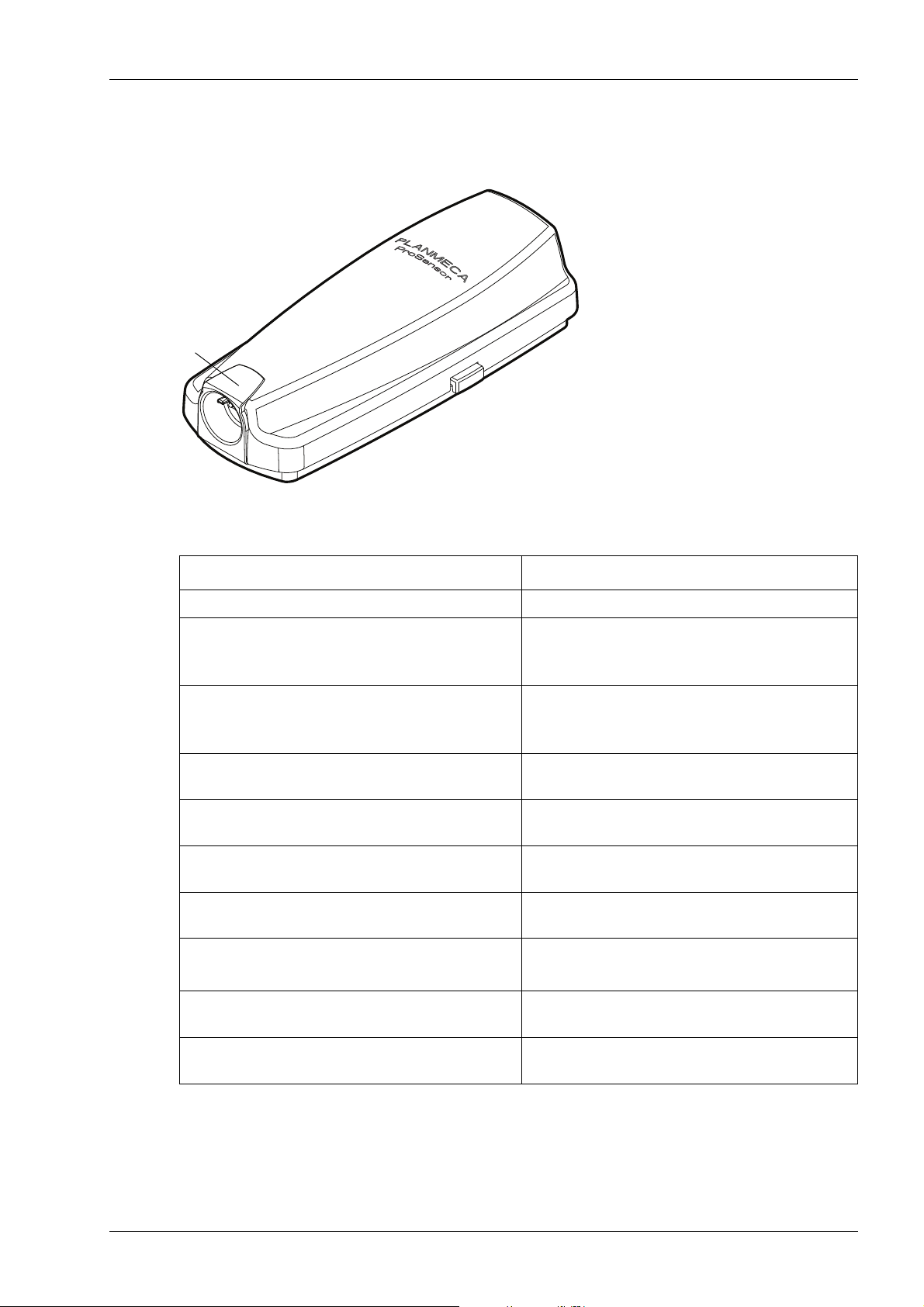
PLANMECA PROSENSOR CONTROLBOX INDICATOR LIGHT
control_box_2.eps
Planmeca
indicator light
ProSensor
6 PLANMECA PROSENSOR CONTROLBOX INDICATOR
LIGHT
Table 2. Planmeca ProSensor ControlBox indicator light explanation
CONTROLBOX INDICATOR LIGHT PLANMECA PROSENSOR STATUS
Off Planmeca ProSensor system power off
Planmeca ProSensor system is off (not in
Dim blue
Bright blue
Slowly flashing blue Waiting for Ready
Steady green Waiting for Exposure
Rapidly flashing green
Steady red Error mode
Slowly flashing yellow
intraoral exposure-mode and the cable is
connected to the ControlBox)
Planmeca ProSensor system is on (Imaging
program communicates with the Planmeca
ProSensor system)
The exposure is taken and image is
transferred from the sensor to the ControlBox
Service mode
Uploading ControlBox software
Slowly flashing blue, turns to slowly flashing
dim blue, then to quickly
Flashing violet ControlBox startup with back-up software
User’s Manual
flashing dim blue
NOTE The exposure can only be taken when the Planmeca
ProSensor ControlBox indicator light is green and
steady, not when the indicator light is flashing.
Reading calibration files from the sensor.
Planmeca ProSensor 5

BEFORE EXPOSURE
Sensor
Long axis
of the tooth
7 BEFORE EXPOSURE
NOTE Detailed instructions for using Planmeca ProX X-ray
NOTE It is recommended to use a sensor holder. Select the
NOTE In case the environment temperature reaches 40°C
7.1 Positioning the patient
unit and Planmeca Romexis software are given in
their User’s manual, which should be used in
conjunction with this manual.
correct sensor holder according to the type of
exposure, refer to the sensor holder manual supplied
with the sensor holder package.
the sensor surface warms up to its maximum
temperature of 49°C and may feel warm. The surface
temperature of the sensor cools off when in patient
contact.
7.2 Positioning the sensor
Paralleling technique (recommended)
Ask the patient to sit down. Place a protective lead apron
over the patient’s chest.
When using the sensor for the first time the message
Loading calibration files will appear on the Romexis
window.
NOTE When connecting the same sensor to another
workstation the calibration files will be reloaded.
Select the appropriate sensor and connect it to the
Planmeca ProSensor ControlBox.
The sensor is placed to a sensor holder which is used to
align the sensor parallel to the long axis of the tooth.
6 Planmeca ProSensor
Use a long cone for the paralleling technique.
User’s Manual

Bisecting angle technique (optional)
Sensor
Long axis
of the tooth
The patient holds the sensor in place with his finger. The
X-ray beam is directed perpendicularly towards an
imaginary line which bisects the angle between the film
plane and the long axis of the tooth.
The use of the plastic cover is not necessary because the
sensor can be sterilized with liquid. The sterilization must
be done after each patient.
NOTE Be very careful not to put excessive pressure on the
sensor. Do not place a clamp on the sensor. Do not
take occlusal exposures with the sensor, and advise
the user not to bite the sensor.
NOTE Never clamp the sensor package or cable with a
hemostat or an unmodified “Snap-a-ray” holder.
Make sure the Planmeca ProSensor system is ready for
the exposure and communicates with Romexis (refer to
section 6 “PLANMECA PROSENSOR CONTROLBOX
INDICATOR LIGHT” on page 5.
BEFORE EXPOSURE
On how to place the sensor into the patient’s mouth refer
to the sensor holder manual supplied with Planmeca
ProSensor.
User’s Manual
Planmeca ProSensor 7

BEFORE EXPOSURE
7.3 Selecting exposure values
NOTE In the digital imaging mode the highest time value
Table 3. Exposure values for Planmeca ProSensor sensors with 20 cm (8”) cones
Select the digital imaging mode of the unit or adjust the
exposure time according to the table.
that can be selected is 0.80 seconds.
TIME
70 kV/
child
66 kV/
child
63 kV/
child
60 kV/
child
57 kV/
child
55 kV/
child
52 kV/
child
50 kV/
child
70 kV/
adult
66 kV/
adult
63 kV/
adult
60 kV/
adult
57 kV/
adult
55 kV/
adult
52 kV/
adult
50 kV/
adult
I P M mandible
0.01s
0.02s
0.03s
0.04s
0.05s
0.06s
I P M maxilla
I P M maxilla
I P M mandible
I P M maxilla
I P M mandible
I P M maxilla
I P M mandible
I P M maxilla
I P M mandible
I P M mandible
I P M maxilla
I P M mandible
I P M maxilla
I P M mandible
I P M maxilla
I P M mandible
I P M mandible
0.08s
0.10s
0.12s
0.16s
0.20s
0.25s
I P M maxilla
I P M maxilla
I P M mandible
I P M maxilla
I P M mandible
I P M maxilla
I P M maxilla
I P M mandible
I P M maxilla
I P M mandible
I P M maxilla
I P M mandible
I P M maxilla
I P M mandible
0.32s
0.40s
0.50s
0.64s
0.80s
8 Planmeca ProSensor
I INCISORS
P PREMOLARS AND CANINES
M MOLARS
User’s Manual

BEFORE EXPOSURE
Table 4. Exposure values for Planmeca ProSensor sensors with 30 cm (12”) cones
TIME
70 kV/
child
66 kV/
child
63 kV/
child
60 kV/
child
57 kV/
child
55 kV/
child
52 kV/
child
50 kV/
child
70 kV/
adult
66 kV/
adult
63 kV/
adult
60 kV/
adult
57 kV/
adult
55 kV/
adult
52 kV/
adult
50 kV/
adult
0.01s
0.02s
0.03s
0.04s
0.05s
0.06s
0.08s
0.10s
0.12s
0.16s
0.20s
0.25s
0.32s
0.40s
0.50s
0.64s
0.80s
I P M maxilla
I P M mandible
I P M maxilla
I P M mandible
I P M maxilla
I P M mandible
I P M maxilla
I P M mandible
I P M maxilla
I P M mandible
I P M maxilla
I P M mandible
I P M maxilla
I P M mandible
I P M maxilla
I P M mandible
I P M maxilla
I P M mandible
I P M maxilla
I P M mandible
I P M maxilla
I P M mandible
I P M maxilla
I P M mandible
I P M maxilla
I P M mandible
I P M maxilla
I P M mandible
maxilla I P M
mandible I P M
maxilla I P M
mandible I P M
User’s Manual
I INCISORS
P PREMOLARS AND CANINES
M MOLARS
Planmeca ProSensor 9

CAPTURING INTRAORAL IMAGES
8 CAPTURING INTRAORAL IMAGES
When connecting the sensor for the first time the
message Loading calibration files will appear on the
Romexis window. Also if you connect the same sensor to
another workstation the files will be loaded again.
8.1 Capturing single intraoral images
1. Click the Intraoral Exposure button on the upper toolbar to
initiate the intraoral image capture mode.
2. The Intraoral Exposure window appears.
3. When the X-ray unit is in ready state a message Waiting
for Ready appears on top of the window.
10 Planmeca ProSensor
4. Prepare the patient for exposure, select exposure
parameters and position Planmeca ProX as required, for
more information refer to Planmeca ProX user’s manual.
NOTE Inform the patient that the sensor may feel warm in
the mouth.
User’s Manual

CAPTURING INTRAORAL IMAGES
When the Planmeca ProSensor system is ready for
exposure the message Waiting for Exposure appears on
top of the window.
5. Take an exposure as usual.
After the exposure a message stating Saving the image
appears on the display and the image is automatically
stored into the database.
6. Define the tooth numbers and sensor orientation and take
the next exposure, or click Done to return to the Imaging
module when all exposures have been captured.
User’s Manual
NOTE Remove the sensor from patient’s mouth when all
exposures have been taken.
Planmeca ProSensor 11

CAPTURING INTRAORAL IMAGES
8.2 Capturing images into a study template
The images are captured into study templates containing
a predefined set of multiple images.
To capture intraoral images into a study template click this
button.
1. Select the desired study template from the list.
At the beginning of the list there are empty templates and
at the bottom of the list there are studies with dates that
already include images captured earlier.
While capturing images using a template, Planmeca
Romexis navigates through the template in a predefined
order, denoting the current image to be captured by a blue
border around the slot.
2. Follow the tooth numbering and sensor orientation as
shown on the image and predefined in the template.
12 Planmeca ProSensor
3. Prepare the patient for exposure, select exposure
parameters and position Planmeca ProX as required, for
more information refer to Planmeca ProX user’s manual.
User’s Manual

CAPTURING INTRAORAL IMAGES
NOTE Inform the patient that the sensor may feel warm in
the mouth.
When the Planmeca ProSensor system is ready for
exposure the message Waiting for Exposure appears on
top of the window. You can now expose the X-ray as
usual. After the exposure a message stating Saving the
image appears on the display and the image is
automatically stored into the database.
To cancel the process click Cancel. The captured images
are saved and the incomplete study is preserved for later
use.
4. Once all images have been captured click Done.
NOTE Remove the sensor from patient’s mouth when all
exposures have been taken.
User’s Manual
Planmeca ProSensor 13

IMAGE QUALITY CONTROL
9 IMAGE QUALITY CONTROL
Verify the image quality after installing the software and
before patient exposure. Perform quality control check
according to the requirements of local authorities, using
for example Quart phantom or similar.
It is recommended to regularly monitor the image quality
using the same phantom according to the requirements of
local authorities. See also the Constancy test manual for
Planmeca Digital Intraoral X-ray System (publication
number 10009324)
Before performing phantom exposures verify that the
brightness and contrast settings of the monitor are
accurate by using a SMPTE test pattern or similar.
9.1 Quality check using SMPTE test pattern
The test image is specified by the Society of Motion
Picture and Television Engineers (www.smpte.org), and
follows the SMPTE Recommended Practise RP 133-1991
Specifications for Medical Diagnostic Imaging Test
Pattern for Television Monitors and Hard-Copy Recording
Cameras. This image should be used for monitor setting
and quality checks performed:
• Before every working day: The 5% gray field inside the
0% field and the 95% gray field inside the 100% field
should be visible. If not, adjust the brightness and contrast
of the monitor.
• Every month: The line raster in the corners and in the
centre must be visible, the vertical and horizontal lines
must form undistorted squares and the homogeneous
grey background must not be coloured.
10 USING THE SENSOR HOLDERS
The sensor holders provide an easy way to position the
sensor for different anatomical and diagnostic needs. For
instructions how to use the sensor holders, please refer to
the manual supplied with the sensor holder package.
14 Planmeca ProSensor
User’s Manual

11 CLEANING
11.1 Surfaces
11.2 Sensors and cables
CLEANING
NOTE Before cleaning the system, always check that the X-
ray unit and the Planmeca ProSensor system are off
(Planmeca ProSensor ControlBox indicator light is
off).
The surfaces can be cleaned with a soft cloth damped in a
mild cleaning solution.
Stronger cleaning agents can be used for disinfecting the
surfaces. We recommend Dürr System-hygiene FD 333
or respective disinfecting solution.
Planmeca ProSensor sensors allow enhanced infection
control in the surgery.
As the sensor casing is hermetically sealed the sensors
can be immersed in disinfectant solution.
NOTE Always use appropriate instruments for cleaning the
sensors.
NOTE It is mandatory to carefully follow the disinfecting and
cleaning recommendations in order to not damage
the sensors.
CAUTION The sensors cannot be sterilized in
autoclave or UV oven.
Wipe up the sensor surface with a soft cloth damped into
a disinfectant solution. The sensors can be soaked in a
disinfection solution as long as there are no nicks in the
cable.
The recommendable disinfectant solutions are Dürr
System Hygiene FD 322 or FD 333 or similar product. The
immersion time with the Dürr disinfectants is 2 minutes.
If more effective disinfection or cold sterilization is
preferred for cleaning, we recommend the
Johnson&Johnson Cidex Opa high level disinfectant at a
minimum temperature of 20° C with maximum immersion
time of 8 minutes for a reuse period not to exceed 14
days.
User’s Manual
NOTE Follow carefully the manufacturer’s
recommendations on immersion time and
recommended disinfectant liquids.
Planmeca ProSensor 15

CLEANING
Do not leave the sensor in the disinfection solution
overnight. The magnetic connector of the sensor cable
should not be soaked.
• Use a new disposable protection cap for every sensor
usage.
• Wipe up the sensor surface with a compress moisten into
a sterile solution.
NOTE The sensor connector can be cleaned using a soft
cloth.
11.3 Sensor holders
For cleaning the sensor holders refer to the manual
supplied with the sensor holder package.
11.4 Planmeca ProSensor ControlBox
The ControlBox can be cleaned with a soft cloth damped
in a mild cleaning solution.
CAUTION Switch off the unit before cleaning.
NOTE Do not disinfect the unit.
16 Planmeca ProSensor
User’s Manual

DISPOSAL OF PLANMECA PROSENSOR
12 DISPOSAL OF PLANMECA PROSENSOR
In order to reduce the environmental load over the
product’s entire lifecycle, PLANMECA’s products are
designed to be as safe as possible to manufacture, use
and dispose of.
Parts which can be recycled should always be taken to
the appropriate processing centres, after hazardous
waste has been removed. Disposal of obsolete systems is
the responsibility of the waste possessor.
All parts and components containing hazardous materials
must be disposed of in accordance with waste legislation
and instructions issued by the environmental authorities.
The risks involved and the necessary precautions must be
taken into account when handling waste products.
Part
Main materials for
disposal
Recyclable
material
Waste
disposal site
Hazardous
waste
(separate
collection)
ControlBox
- metal
- plastic
Cables
Packing
Sensors Return the sensors to Planmeca.
Other parts PoE X
stainless steel
ASA + PC
POM
PC
PU
copper
TPE/PU
cardboard,
paper,
PE foam
NOTE If the component boards cannot be recycled handle
X
X
X
X
X
X
X
them as electronic scrap, i.e. according to the local
legislation.
X
X
X
User’s Manual
Planmeca ProSensor 17

TECHNICAL SPECIFICATIONS
13 TECHNICAL SPECIFICATIONS
Sensors
Sensor type CMOS with scintillator
Sensor dimensions
Size 0
overall 33.6 x 23.4 mm (1.33 x 0.92 in.)
active area 25.5 x 18.9 mm (1,00 x 0,74 in.)
number of pixels 850 x 629
view delay <5 sec.
Size 1
overall 39.7 x 25.05 (1.56 x 0.99 in.)
active area 31.5 x 20.7 (1.24 x 0.81 in.)
number of pixels 1050 x 690
view delay <5 sec.
Size 2
overall 44.1 x 30.4 mm (1,74 x 1.2 in.)
active area 36 x 26.1 mm (1,74 x 1,2 in.)
number of pixels 1200 x 870
view delay <5 sec.
Resolution 17 lp/mm
Theoretical resolution 33 lp/mm
Cable length 0.86 m (33.9 in.) or 2.0 m (78.7 in.)
Expected service life 10 years / 100 000 exposure cycles
Supported operating systems
Client Server
Windows XP Pro (32 bit) Windows XP Pro (32 bit)
Windows Vista Pro (32 or 64) Windows 2003 Server (32 or 64)
Windows 7 Pro (32 or 64) Windows 2008 Server (32 or 64)
Windows 8 Pro (32 or 64) Windows Vista Pro (32 or 64)
Mac OS X (Intel)* Windows 7 Pro (32 or 64)
Windows 8 Pro (32 or 64)
Mac OS X (Intel)
18 Planmeca ProSensor
User’s Manual

TECHNICAL SPECIFICATIONS
Ethernet ControlBox
Dimensions 112 x 46 x 24 mm (4.41 x 1.81 x 0.94 in.)
Power supply 48 V DC 65 mA
Cables
ControlBox to PoE RJ45 10m OR 15m
PoE to LAN RJ45 10m OR 15m
Power supply Phihong Single Port Injector
Type: PSA16U-480 (POE)
Input voltage 100-240 VAC (50-60 Hz)
Output voltage 48VDC
Max. output current 0.35 A
Insulation voltage
Primary-secondary 3000VDC
USB ControlBox
Dimensions 112 x 46 x 24 mm (4.41 x 1.81 x 0.94 in.)
Cables fixed USB 2.0 power supply cable 2 or 5m
(6.6 or 16.4 ft)
Power supply Input power 2 W
Operating environment
Planmeca ProSensor is for indoor use only. The equipment is installed on the wall or on/under the
table. The user moves the sensor into the operation position by hand.
The room and operation must comply with the x-ray safety shielding requirements according to
radiation safety regulation in the country.
The system is used by dental care professionals.
Prior to installation of the system check that the local conditions are compatible with the appliance
design.
The temperature of the operating environment should be between + 15°C and + 40°C.
The relative humidity of the operating environment should not exceed 60%.
Atmospheric pressure range should be between 700 hPa - 1060 hPa.
Transportation and storage environment
Transportation and storage temperature -10°C - +60°C.
The relative humidity during transportation and storage should not exceed 95%.
User’s Manual
Planmeca ProSensor 19

TECHNICAL SPECIFICATIONS
APPENDIX A: EXPOSURE VALUES FOR PLANMECA PROX
NOTE The recommended exposure values are given in
Planmeca ProX User’s manual
“EXPOSURE VALUE TABLES”.
A.1 Default exposure values
When the unit is switched on, the default exposure values
appear on the displays.
Short cone exposure values
PATIENT kV mA time
Adult 63 6 0.125
Child 60 7 0.080
Long cone exposure values
PATIENT kV mA time
section 17
Adult 63 6 0.250
Child 60 7 0.200
For programming these values see the Planmeca ProX
User’s manual section 16.1 “Programming default
exposure values”
20 Planmeca ProSensor
User’s Manual
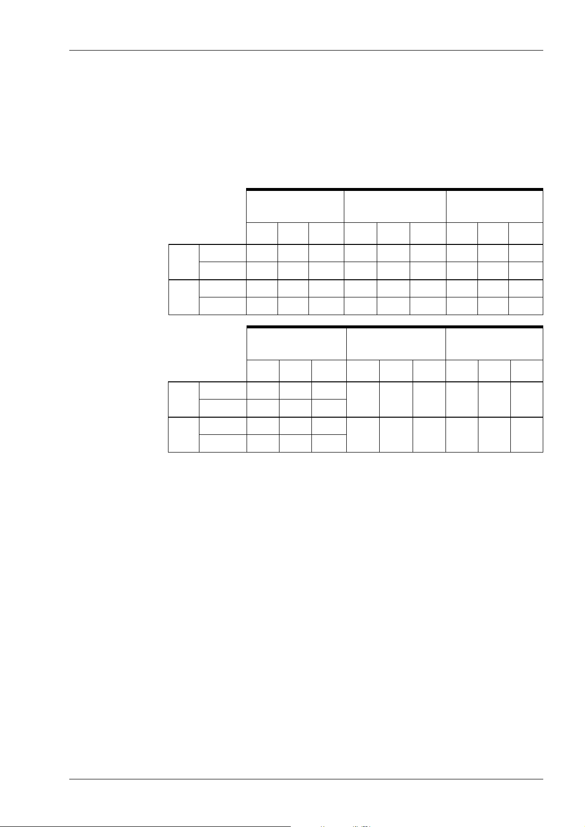
A.2 Preprogrammed settings values
For programming these values see the Planmeca ProX
User’s manual, section 16.3 “Programming the
preprogrammed settings”.
NOTE Two sets of exposure values (time/kV/mA) have been
programmed for each exposure region: one for adult
mode and one for child mode.
TECHNICAL SPECIFICATIONS
Adult
Child
Adult
Child
INCISORS
kV mA time kV mA time kV mA time
Maxilla 60 7 0.100 63 6 0.1 63 6 0.125
Mandible 60 7 0.08 63 6 0.08 63 6 0.100
Maxilla 60 7 0.063 60 7 0.08 60 7 0.100
Mandible 60 7 0.05 60 7 0.064 60 7 0.080
OCCLUSAL
EXPOSURE
kV mA time kV mA time kV mA time
Maxilla 70 6 0.100
Mandible 70 6 0.100
Maxilla 66 6 0.080
Mandible 66 6 0.080
PREMOLARS AND
CANINES
ENDODONTIC BITE-WING
60
60
7
7
0.100 60
0.080 60
MOLARS
7
7
0.100
0.080
User’s Manual
Planmeca ProSensor 21

TECHNICAL SPECIFICATIONS
When using the 30 cm long cone program see Planmeca
ProX User’s manual section 17 “EXPOSURE VALUE
TABLES” or select three steps darker density (longer
exposure time).
Adult
Child
Adult
Child
INCISORS
kV mA time kV mA time kV mA time
Maxilla 60 7 0.200 63 6 0.200 63 6 0.250
Mandible 60 7 0.160 63 6 0.160 63 6 0.200
Maxilla 60 7 0.125 60 7 0.160 60 7 0.200
Mandible 60 7 0.100 60 7 0.125 60 7 0.160
OCCLUSAL
EXPOSURE
kV mA time kV mA time kV mA time
Maxilla 70 6 0.200
Mandible 70 6 0.200
Maxilla 66 6 0.125
Mandible 66 6 0.125
PREMOLARS AND
CANINES
ENDODONTIC BITE-WING
60
60
7
7
0.200 60
0.160 60
MOLARS
7
7
0.200
0.160
22 Planmeca ProSensor
User’s Manual


Planmeca Oy | Asentajankatu 6 | 00880 Helsinki | Finland
tel. +358 20 7795 500 | fax +358 20 7795 555 | sales@planmeca.com | www.planmeca.com
 Loading...