

Planmeca Intra Service manual

10006491_12
EN
technical manual


TABLE OF CONTENTS
1 GENERAL & TECHNICAL DATA .......................................................... 1
1.1 Warnings and cautions ................................................................................................................ 1
1.2 Manual versions ........................................................................................................................... 2
1.3 Technical specifications ............................................................................................................... 3
1.4 User’s statement for Planmeca Intra ........................................................................................... 5
1.5 EMC information .......................................................................................................................... 8
2 SERVICE MODE ................................................................................... 12
2.1 Control panel ............................................................................................................................. 12
2.2 How to enter/exit the service mode ........................................................................................... 12
2.3 X-ray tube filament preheating voltage calibration ..................................................................... 13
2.4 kV range selection ..................................................................................................................... 13
2.5 Operation of the preprogrammed settings keys (kV hold) ......................................................... 14
2.6 Dimming the displays ................................................................................................................. 15
2.7 Duration of the displays dimming time-out ................................................................................. 16
2.8 Disabling the exposure key ........................................................................................................ 17
2.9 Automatic identification of the cascade card ............................................................................. 18
2.10 Specifying the PCB versions ..................................................................................................... 18
2.11 Ready-state setting .................................................................................................................... 19
3 RECALLING THE FACTORY PREPROGRAMMED EXPOSURE
VALUES ................................................................................................ 20
4 TROUBLESHOOTING .......................................................................... 21
5 ERROR MESSAGES ............................................................................ 22
5.1 Error message shortform table .................................................................................................. 22
5.2 Detailed error message explanations ........................................................................................ 23
6 MECHANICAL ADJUSTMENTS .......................................................... 28
6.1 Adjusting the balance of the arm ............................................................................................... 28
6.2 Adjusting the bracket arm angles .............................................................................................. 29
6.3 Adjusting the stiffness of the tube head’s horizontal axle .......................................................... 30
6.4 Vertical tube head stiffness adjustment screw ........................................................................... 31
7 PARTS REPLACEMENT & REPAIR .................................................... 32
7.1 Replacing the Generator PCB ................................................................................................... 32
7.2 Replacing the tube head PCB ................................................................................................... 35
7.3 Replacing the tube head ............................................................................................................ 36
7.4 Replacing the arm cables .......................................................................................................... 37
7.5 Replacing the control panel cable .............................................................................................. 44
8 DIAGRAMS ........................................................................................... 45
COPYRIGHT PLANMECA 2007-10
PUBLICATION NUMBER 10006491 revision 12
Technical manual
Planmeca Intra x-ray unit TOC-1

1 GENERAL & TECHNICAL DATA
1.1 Warnings and cautions
WARNING
THE FOLLOWING WARNINGS, CAUTIONS AND NOTES MUST
ALWAYS BE CONSIDERED WHILE SERVICING THE UNIT, IN ORDER
TO AVOID EITHER PERSONAL INJURY OR DAMAGE TO THE UNIT.
CAUTION
RADIATION SAFETY RULES
Some procedures described in this manual produces X-ray radiation.
Always follow the rules for radiation protection.
Never attempt to open the tube head. It does not contain any
serviceable parts, and radiation safety could not be guaranteed any
more.
GENERAL & TECHNICAL DATA
CAUTION
ELECTRICAL SAFETY RULES
The unit contains hazardous voltages. While servicing internal parts,
always turn off externally the power to the unit, and wait for 2 minutes
before touching any electrical parts.
Always replace the fuses with ones of the same type and rating.
Otherwise patient, operator or equipment safety cannot be
guaranteed.
The circuit boards can be damaged due to static discharges and
require careful handling.
CAUTION
GENERAL SAFETY RULES
The unit must be serviced only by qualified personnel, trained by
PLANMECA. Repairs and parts replaced by unqualified personnel
carry no warranty.
Periodical maintenance as described in this manual must be
performed on a regular basis, to ensure the safety and image quality
of the unit.
Some procedures described in the unit could be dangerous, if not
followed as stated.
Technical manual
Planmeca Intra x-ray unit 1

GENERAL & TECHNICAL DATA
CAUTION
1.2 Manual versions
Planmeca pursues a policy of continual product development. Although every effort is made
to produce up-to-date product documentation this publication should not be regarded as an
infallible guide to current specifications. We reserve the right to make changes without prior
notice.
NOTE This manual is only valid for the software versions from 3.01 and
Check that the X-ray unit is installed properly and no mechanical play
caused by wear, corrosion, metal fatigue or ageing can be found
between the wall bracket and horzontal arm.
later.
2 Planmeca Intra x-ray unit
Technical manual

1.3 Technical specifications
Generator Constant potential, microprocessor controlled,
X-ray tube Toshiba D-0711SB
Focal spot size 0.7 mm according to IEC 60336
Cone diameter 60 mm (2.36 in.)
Max. symmetrical radiation field ø 60 mm at SSD 200 mm
Total filtration min. 2 mm Al equivalent at 70 kV
Inherent filtration 1 mm Al equivalent at 70 kV
Anode voltage 50, 52, 55, 57, 60, 63, 66, 70 kV, ±2 kV
Anode current 8, 7, 6, 5, 4, 3, 2 mA ±(5% + 0.2 mA)
Target angle 16°
Exposure times 0.01-3.2 sec. ±(5% + 0.001 sec.), 26 steps
Reference current time product 8 mAs at 70 kV, 8 mA, 1 sec.
Lowest current time product 0.02 mAs at 2 mA, 0.01 sec.
Max. nominal anode voltage 70 kV
Max. electrical output 560 W at 70 kV, 8 mA
Electrical output at 0.1 sec. 560 W at 70 kV, 8 mA
Max. loading energy 1800 mAs/h at 70 kV
SSD (Source-Skin Distance)
Standard/Long
Long with rectangular collimator
Mains voltage 100 V~/110-115 V~/220-240 V~
Apparent resistance 0.3 ohms 110-115 V~ /
Mains frequency 50/60 Hz
Fusing 8 AT 250 VAC at 220-240V~
Duty cycle 1:15, automatic control
Electrical classification Class I
GENERAL & TECHNICAL DATA
operating frequency 66 kHz
Rectangular 33 x 43 mm (1.30 x 1.69 in.)
ø 60 mm at SSD 300 mm
according to IEC 806
according to IEC 60522
according to IEC 60522
200 mm (8 in.)/300 mm (12 in.)
306 mm (12.04 in.)
0.8 ohms 220-240 V~
15 AT 250 VAC at 100 V~/110-115 V~
Type B
Technical manual
Planmeca Intra x-ray unit 3

GENERAL & TECHNICAL DATA
Mechanical data
Weight total 23 kg (51 lbs)
Color RAL 9016
Environmental requirements
Ambient temperature operating +5°C - +40°C storage -10°C - +50°C
Humidity 25% - 75%
External mains fuse recommendation
The recommendation for the external mains fuses are:
• units with 100V~ or 115V~ voltage setting: 16A, time lag
• units with 220-240V~ voltage setting: 10A, time lag
No other equipment should be connected to the same fused mains line as the x-ray unit. In
some countries an additional external fault current guard is also required.
tube head 4.2 kg (9.3 lbs) with standard cone
4.5 kg (10 lbs) with long cone
Original manufacturer
PLANMECA Oy, Asentajankatu 6, FIN-00880, Helsinki, FINLAND
phone: +358-20-7795 500
4 Planmeca Intra x-ray unit
Technical manual

GENERAL & TECHNICAL DATA
1.4 User’s statement for Planmeca Intra
Radiation leakage technique factors
The maximum rated peak tube potential is 70 kV and the maximum rated continuous tube
current is 0.53 mA for the maximum rated peak tube potential.
Minimum filtration
The radiation port contains an added 1.0 mm aluminium filtration. The measured half-value is
0.50 - 0.55 at 70 kV. The measured value corresponds to an aluminium equivalent of 2.0 mm.
Rated line voltage
100, 110-117, 220-240 V~ ±10%. Line voltage regulation 10%.
Maximum line current
6.1 A at 230 V~, 12.2 A at 115 V~
Technique factors that constitute the maximum line current condition
70 kV, 8 mA
Generator rating and duty cycle
1.4 kW, duty cycle 1:15. The wait period is controlled automatically by calculating it according
to the formula tw = 15 x texp.
Maximum deviation of peak tube potential from indicated value
± 2.0 kV
Maximum deviation of tube current from indicated value
±10%
Maximum deviation of exposure time from indicated value
±10%
DEFINITION OF MEASUREMENT CRITERIA
Exposure time
The beginning and end points of the exposure time are defined at 70% of the peak radiation
waveform measured with a calibrated x-ray monitor.
Peak tube potential
Is defined as the high voltage mean value measured with a calibrated non-invasive kVp
meter.
Technical manual
Tube current
Is defined using the voltage over the feedback resistor measured with a calibrated multimeter.
The mA value is calculated by dividing the voltage by the resistance value.
Planmeca Intra x-ray unit 5
GENERAL & TECHNICAL DATA
The nominal x-ray voltage together with the highest x-ray tube current
obtainable from the high-voltage generator when operated at it’s highest xray tube voltage
70 kV, 8 mA
The nominal x-ray tube current when operated at the highest x-ray tube
voltage
8 mA, 70 kV
The x-ray tube voltage and tube current which result in the highest electric
output power
70 kV, 8 mA
The nominal electric power for a load time of 0.1 sec and at the nominal xray tube voltage
1.4 kW at 70 kV, 8 mA
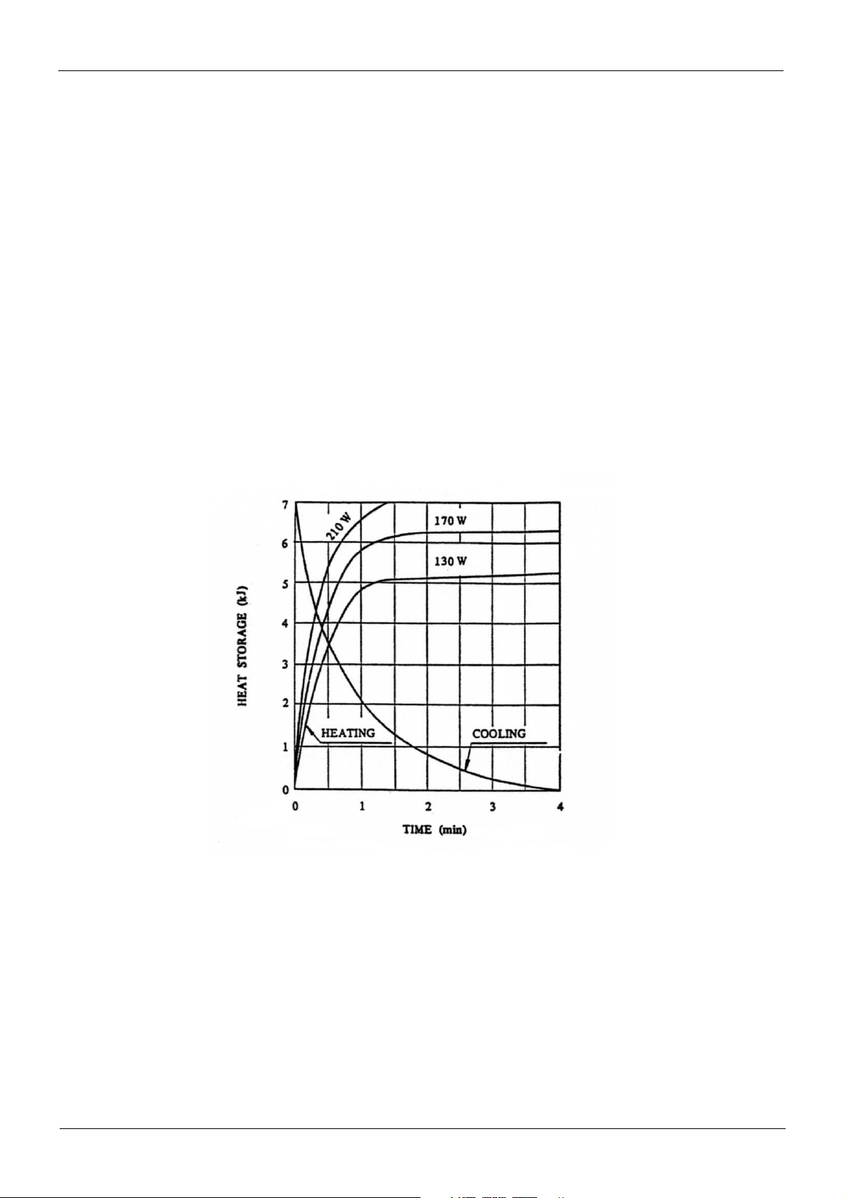
Anode heating/cooling curve of the X-ray tube
6 Planmeca Intra x-ray unit
Technical manual

X-ray tube assembly heating/cooling curve
X-ray tube assembly heating/cooling curve
GENERAL & TECHNICAL DATA
140
120
100
80
60
Heat S torage (kJ)
40
20
0
0 30 60 90 120 150 180 210 240 270 300
18 W
13 W
Cooling
Time (min)
Technical manual
Planmeca Intra x-ray unit 7
GENERAL & TECHNICAL DATA
1.5 EMC information
WARNING
WARNING
Use of any accessories and cables other than those specified in
Planmeca Intra X-ray unit’s documentation, with exception of cables
sold by Planmeca as replacement parts for internal components, may
result in increased emission or decreased immunity of the X-ray unit.
Planmeca Intra X-ray unit should not be used adjacent to or stacked
with other equipment. If adjacent or stacked use is necessary, the
Planmeca Intra X-ray unit should be observed to verify normal
operation in configuration which it will be used.
Guidance and manufacturer’s declaration - electromagnetic emissions
Planmeca Intra X-ray unit is intended for use in the electromagnetic environment specified
below. The customer or the user of the Planmeca Intra X-ray unit should assure that it is used in
such an environment.
Emissions test Compliance Electromagnetic environment – guidance
RF emissions
CISPR 11
RF emissions
CISPR 11
Harmonic emissions
IEC 61000-3-2
Voltage fluctuations/
flicker emissions
IEC 61000-3-3
Group 1
Class B
Class A
Complies
Planmeca Intra X-ray unit uses RF energy only
for its internal function. Therefore, its RF emissions are very low and are not likely to cause any
interference in nearby electronic equipment.
Planmeca Intra X-ray unit is suitable for use in all
establishments, including domestic establishments and those directly connected to the public
low-voltage power supply network that supplies
buildings used for domestic purposes.
8 Planmeca Intra x-ray unit
Technical manual

GENERAL & TECHNICAL DATA
Guidance and manufacturer’s declaration - electromagnetic immunity
Planmeca Intra X-ray unit is intended for use in the electromagnetic environment specified below. The customer or the user of Planmeca Intra X-ray unit should assure that it is used in such an environment.
Immunity test
Electrostatic
discharge (ESD)
IEC 61000-4-2
Electrical fast
transient/burst
IEC 61000-4-4
Surge
IEC 61000-4-5
Voltage dips, short
interruptions and
voltage variations
on power supply
input lines
IEC 61000-4-11
IEC 60601
test level
±6 kV contact
±8 kV air
±2 kV for power
supply lines
±1 kV for input/output
lines
±1 kV line to line
±2 kV line to earth
<5 %
U
(>95 % dip in
T
U
)
T
for 0,5 cycle
U
40 %
(60 % dip in
T
U
)
T
for 5 cycles
70 %
U
(30 % dip in
T
U
)
T
for 25 cycles
<5 %
U
(>95 % dip in
T
U
)
T
for 5 s
Compliance level
±6 kV contact
±8 kV air
±2 kV for power
supply lines
±1 kV for input/output
lines
±1 kV line to line
±2 kV line to earth
U
<5 %
(>95 % dip in
T
U
)
T
for 0,5 cycle
U
40 %
(60 % dip in
T
U
)
T
for 5 cycles
70 %
U
(30 % dip in
T
U
)
T
for 25 cycles
<5 %
U
(>95 % dip in
T
U
)
T
for 5 s
Electromagnetic environment-
guidance
Floors should be wood, concrete
or ceramic tile. If floors are covered with synthetic material, the
relative humidity should be at
least 30%.
Mains power quality should be
that of a typical commercial or
hospital environment
Mains power quality should be
that of a typical commercial or
hospital environment.
Mains power quality should be
that of a typical commercial or
hospital environment. If the user
of Planmeca Intra X-ray unit
requires continued operation during power mains interruptions, it
is recommended that Planmeca
Intra X-ray unit be powered from
an uninterruptible power supply.
Power frequency(
50/60 Hz)
magnetic field
IEC 61000-4-8
NOTE
U
Technical manual
3 A/m 3 A/m
is the a.c. mains voltage prior to application of the test level.
T
Power frequency magnetic fields
should be at levels characteristic
of a typical location in a typical
commercial or hospital environment. The power frequency magnetic field should be measured in
the intended installation location
to assure that it is sufficiently low.
Planmeca Intra x-ray unit 9
GENERAL & TECHNICAL DATA
Guidance and manufacturer’s declaration - electromagnetic immunity
Planmeca Intra X-ray unit is intended for use in the electromagnetic environment specified below. The
customer or the user of Planmeca Intra X-ray unit should assure that it is used in such an environment.
Immunity test
Conducted RF
IEC 61000-4-6
Radiated RF
IEC 61000-4-3
IEC 60601
test level
3 Vrms
150 kHz to 80 MHz
3 V/m
80 MHz to 2.5 GHz
Compliance
level
3 Vrms
3 V/m
Electromagnetic environment-
guidance
Portable and mobile RF communications
equipment should be used no closer to any
part of the Planmeca Intra X-ray unit, including cables, than the recommended separation distance calculated from the equation
applicable to the frequency of the transmitter.
Recommended separation distance
d1.2P=
d1.2P= 80 MHz to 800 MHz
d2.3P=
800 MHz to 2.5 GHz
where P is the maximum output power rating of the transmitter in watts (W) according
to the transmitter manufacturer and d is the
recommended separation distance in
metres (m).
Field strengths from fixed RF transmitters,
as determined by an electromagnetic site
survey,
level in each frequency range.
a
should be less than the compliance
b
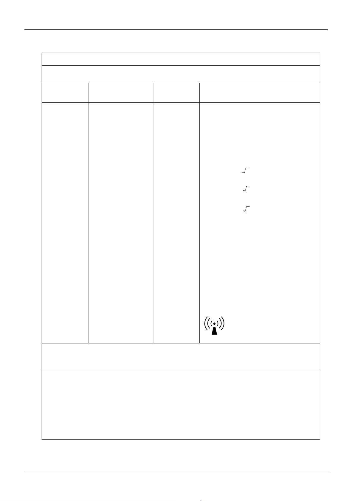
Interference may occur in the vicinity of
equipment marked with the following symbol:
NOTE 1: At 80 MHz and 800 MHz, the higher frequency range applies.
NOTE 2: These guidelines may not apply in all situations. Electromagnetic propagation is affected by
absorption and reflection from structures, objects and people.
a
Field strengths from fixed transmitters, such as base stations for radio (cellular/cordless)
telephones and land mobile radios, amateur radio, AM and FM radio broadcast and TV broadcast
cannot be predicted theoretically with accuracy. To assess the electromagnetic environment due
to fixed RF transmitters, an electromagnetic site survey should be considered. If the measured
field strength in the location in which Planmeca Intra X-ray unit is used exceeds the
applicable RF compliance level above, Planmeca Intra X-ray unit should be observed to
verify normal operation. If abnormal performance is observed, additional measures may be
necessary, such as re-orienting or relocating Planmeca Intra X-ray unit.
b
Over the frequency range 150 kHz to 80 MHz, field strengths should be less than 3 V/m.
10 Planmeca Intra x-ray unit
Technical manual

GENERAL & TECHNICAL DATA
Recommended separation distances between
portable and mobile RF communications equipment and Planmeca Intra X-ray unit
Planmeca Intra X-ray unit is intended for use in an electromagnetic environment in which radiated RF disturbances are controlled. The customer or the user of Planmeca Intra X-ray unit can help prevent electromagnetic interference by maintaining a minimum distance between portable and mobile RF
communications equipment (transmitters) and the Planmeca Intra X-ray unit as recommended below,
according to the maximum output power of the communications equipment.
Rated maximum output power
of transmitter
W
0.01 0.2 0.2 0.3
0.1 0.4 0.4 0.7
1 1.2 1.2 2.4
10 4.0 4.0 8.0
100 12.0 12.0 24.0
Separation distance according to frequency of transmitter
m
150 kHz to 80 MHz 80 MHz to 800 MHz 800 MHz to 2.5 GHz
d1.2P= d1.2P= d2.3P=
Technical manual
Planmeca Intra x-ray unit 11
SERVICE MODE
2 SERVICE MODE
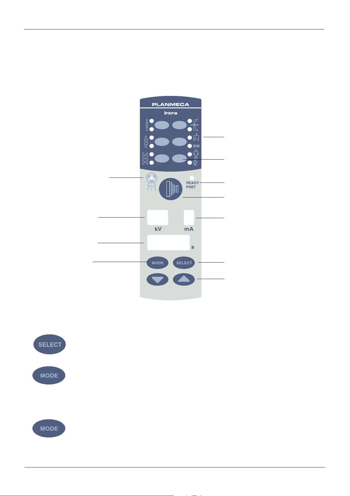
2.1 Control panel
Exposure warning
indicator light
Preprogrammed setting
keys and indicator lights
Adult/child selection key
and indicator light
Ready indicator light
kV display
Time display
Mode key
66
0.250
8
2.2 How to enter/exit the service mode
Press and hold down the select key for 4 seconds.
Exposure key
mA display
Select key
Parameter adjustment keys
Press and hold down the Mode key for more than 2 seconds, until the four uppermost preprogrammed setting indicator lights come on.
To exit from the service mode
Press the Mode key briefly.
12 Planmeca Intra x-ray unit
Technical manual
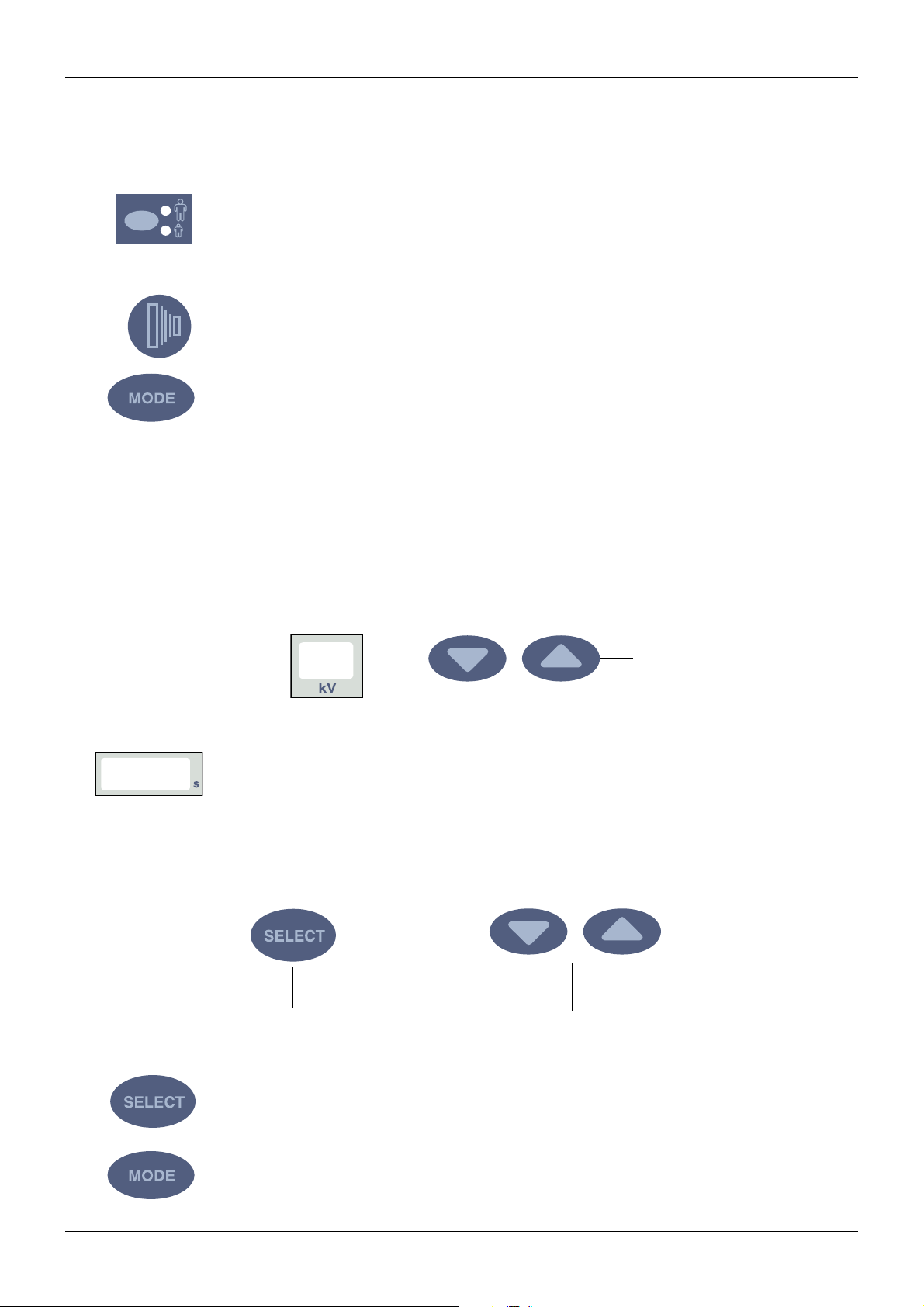
2.3 X-ray tube filament preheating voltage calibration
Enter the service mode according to the instruction given in section 2.2 “How to enter/exit the
service mode” on page 12.
Press and hold down the adult/child mode selection key for 2 seconds or until the indicator
light starts to blink. The indicator lights will start to blink indicating that you are in the preheating voltage calibration mode.
Move as far away from the x-ray tube as the length of the cable from the control panel permits.
Press and hold the exposure key on the control panel until 16 exposures are performed
(approx. 30 seconds).
Press the Mode key briefly to exit the service mode.
2.4 kV range selection
SERVICE MODE
0
Enter the service mode according to the instruction given in section 2.2 “How to enter/exit the
service mode” on page 12.
Press the parameter adjustment up key until the parameter number 14 appears on the kV display.
14
The code of the kV range (0 - 9) is shown on the time display. The kV ranges are: 0 = 50-70,
1 = 55-70, 2 = 60-70, 3 = 66-70, 4 = 70, 5 = 50-68, 6 = 55-68, 7 = 60-68, 8 = 66-68 and 9 = 68
kV.
Press the Select key until the kV range code starts to blink, and the range can now be
changed with the parameter adjustment keys.
Parameter adjustment up -key
Technical manual
Parameter adjustment keysSelect key
Accept the new kV range by pressing the Select key.
Press the Mode key briefly to exit the service mode.
Planmeca Intra x-ray unit 13
 Loading...