


ANTS!
PLANKTON ELECTRONICS


INDEX
WARRANTY ................................................................................................................................................................2
ABOUT THIS MANUAL................................................................................................................................................ 3
OVERVIEW ..................................................................................................................................................................3
TERMINOLOGY ...........................................................................................................................................................4
compatibility ........................................................................................................................................................4
POWER ........................................................................................................................................................................5
FIRST STEPS............................................................................................................................................................... 5
BASICS........................................................................................................................................................................ 8
NORMALLED SYSTEM...............................................................................................................................................12
MIDI ............................................................................................................................................................................14
OSCILLATORS............................................................................................................................................................17
LFOS ..........................................................................................................................................................................23
VCF............................................................................................................................................................................24
ENVELOPES............................................................................................................................................................... 27
VCAS.........................................................................................................................................................................30
NOISE ........................................................................................................................................................................32
MIXER .......................................................................................................................................................................32
SAMPLE AND HOLD...................................................................................................................................................33
AND GATE .................................................................................................................................................................35
HACKING...................................................................................................................................................................36
THE END ....................................................................................................................................................................37
SPECIFICATIONS ......................................................................................................................................................38

2
WARRANTY
Plankton Electronics warrants this product to be free of any defect in the
manufacturing or materials for a period of one year from the date of
purchase. This warranty does not cover any damage or malfunction caused
by incorrect use – such as, but not limited to, power cables connected
backwards, excessive voltage levels, or exposure to extreme temperature or
moisture levels.
The warranty covers replacement or repair, as decided by Plankton
Electronics. Please, contact our customer service for a return authorization
before sending the module (support@planktonelectronics.com). The cost
of sending a module back for servicing is paid for by the customer.
Plankton Electronics implies and accepts no responsibility for harm to
person or apparatus caused through operation of this product.
As an open-source product, we encourage to mod and hack it, but we will
not provide any assistance on how to do it. Any malfunction caused by a
mod will not be covered by this warranty.

3
ABOUT THIS MANUAL
This manual has been written with the synth newbie in mind. It’s a synth
manual but at the same time a tutorial and a basic synthesis manual. We
recommend to follow it step by step with the synth in front of you.
If you have any comments, write us to: support@planktonelectronics.com
We will be happy to receive them.
This manual has been written by:
Àlex Ballester
PLANKTON ELECTRONICS
May 2017
www.planktonelectronics.com
Manual version: 1.3
OVERVIEW
ANTS! is an analog patchable synthesizer. It is designed to work as a
modular synth, connecting patch cables to generate sounds, but at the
same time it can work without the use of cables. These pre-patched
connections (normalled connections) make the synth an (almost) ready to
play 2-osc analog mono-synth. By plugging a patch cable into a normalled
input, the normalled connection is broken so you can experiment with new
and weird sounds, basses, leads, drums, pads, self-generative patches and
happy accidents.
ANTS! is transparent: there are no layers, no double functions, no storing.
Everything is in front of the user* and it is very simple to use: you just need
to connect the outputs to the inputs. At the same time the 51 patch points
and the 25 potentiometers give you the option to design complex patches
and sounds. The possibilities are endless.
* The only hidden aspect is the internal routing of the machine, the normalled
system. ANTS! is already prepatched inside to make it easy to use. If you want to
know more about this feature jump to the NORMALLED SYSTEM chapter.

4
TERMINOLOGY
In this manual, we will use some words that may confuse you if you are a
newbie in the synth world.
CW: Clockwise. --- e.g. Turn the RATE potentiometer CW ---
CCW: Counter clockwise. --- e.g. Turn the FREQ potentiometer CCW ---
Pot: potentiometer.
NS: 'Ninja Star'. It is a device used to split the signals. Often we want to
send a signal to more than one destination. This is done by using a passive
splitter like the 'Plankton Ninja Stars'. You are free to use other devices, like
stackable cables, or other splitters. An ANTS! pack come with some Ninja
Stars ready to use.
NINJA STAR
Compatibility
ANTS! uses 3.5mm mono jack connectors. All the voltages are compatible
with the EURORACK standard. Oscillators offer +/-4V of signal output and
work with 1V/Oct inputs to play it musically. We encourage exploring the
possibilities offered by playing the synth together with other eurorack
modules, controllers, sequencers and MIDI and analog keyboards.
A MIDI keyboard or controller connected through the MIDI TO CV converter
can control the synth. At the same time any keyboard or step sequencer
with analog CV and GATE outputs can be used to control the machine. You
can use more than one controller, or just play the synth without any
controller. Test all the possibilities!

5
POWER
ANTS! is powered with 12Vac. A power supply is included with the synth.
Please, use only the provided power supply. Using the wrong power supply
can cause malfunction or even damage the unit.
Connect the power supply to the
power connector of the left
labelled as '12Vac'. Notice that the
3.5mm jack is for the MIDI cable.
FIRST STEPS
Before reading the manual , we think you’ll want to start making sounds.
Connect the power supply to the ANTS! and set the potentiometers as show
below. Connect the VCA2 OUT to your mixer, amp, or FX unit (be careful
with the levels). Now push the AD ENV1 MANUAL button. You should hear a
bass like sound.
* Note: the transparent knobs are not used in this patch. Their position is not
relevant.

6
Now you are hearing the XTOSC·Y through the filter (VCF) and the VCA.
Both, VCF and VCA, are controlled by the AD ENV1. We will see more about
this routing later in this manual.
Change the RATE knob of the XTOSC·Y and play triggering the envelope. You
should hear the tone changes. Play with the FREQ, Q, ATTACK, RELEASE and
PWM controls.
Take your time to explore and play.
****************************************************************
Connect the XTOSC ·X SQUARE OUT to the AD ENV1 TRIG input like this:
Notice that the XTOSC ·X switch is activated (pressed). This activates the
LFO mode. The LED must blinks ON and OFF. Now the synth should sound
at a constant rate defined by the XTOSC ·X RATE. Play with it.

7
Connect a wire from S/H OUT to XTOSC·Y V/OCT. Look at the
potentiometers position:
ou should hear how the tone changes at each step as a result of the
random voltages generated by the S/H .
Play with all the activated parameters. Tips: Change the VCF mode to HP,
move the XTOSC·Y PWM CCW and move ATTACK, Q and GLIDE CW. You will
note that some small changes in knob position may affect the sound
dramatically. If you find yourself in a place where there is no sound at all
come back to the last picture configuration.
At this point you can:
1. Continue reading the manual and learn how the synth works. Jump the
'BASICS' chapter if you're already familiarized with modular synths.
2. Experiment, tweak knobs, make connections and see what happens.
3. Go to http://ants.metapatch.com to explore and reproduce a large list of
patches and sounds. (http://ants.constructingtowers.com/#/patch for the
beta version).
8
BASICS
ANTS! is a modular synth. This means that you must connect cables from
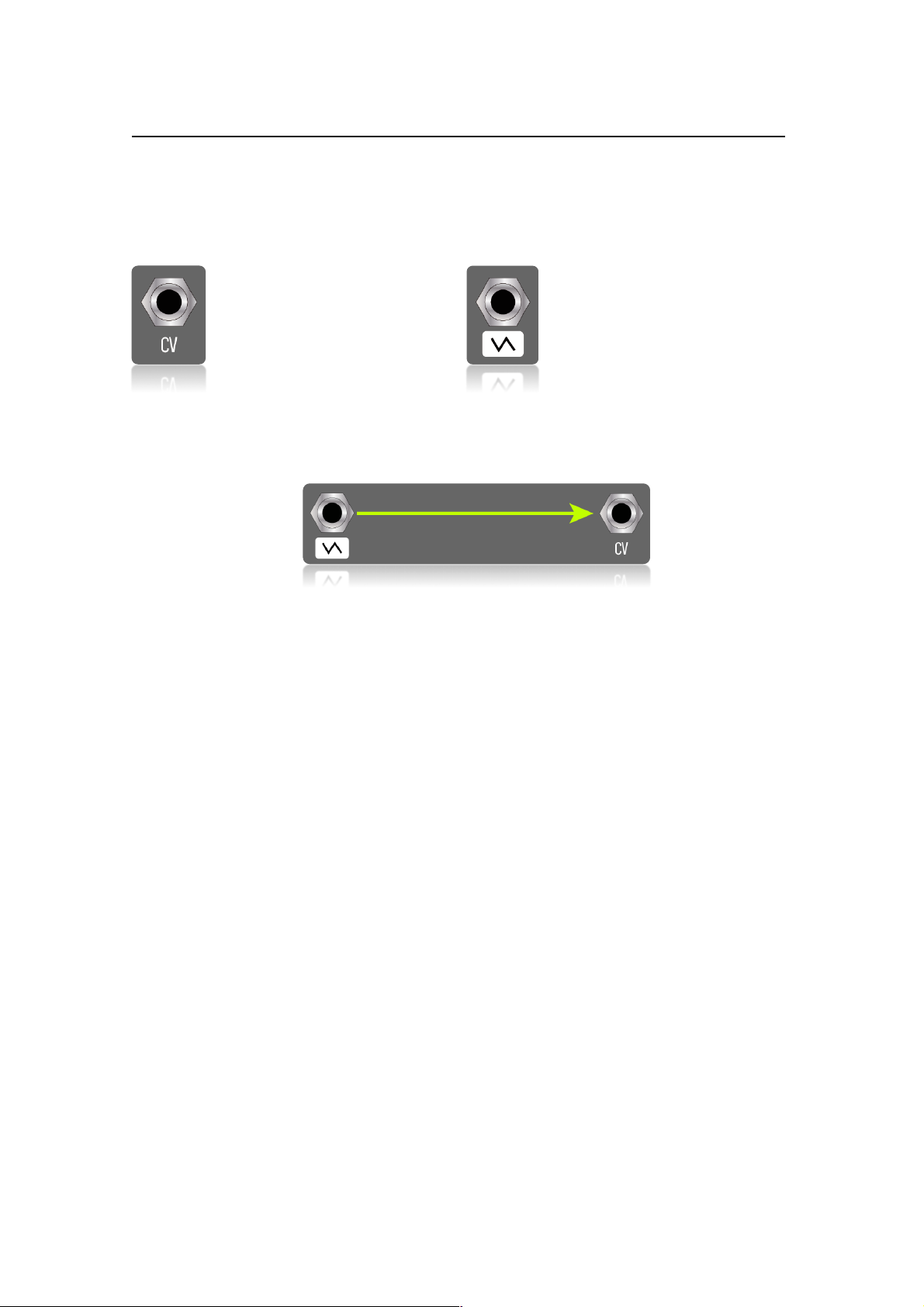
the inputs to the outputs to create your patches. White symbol over black
background represents inputs. Black symbol over a white box, outputs.
This is an input. This is an output.
Patching is easy. You just need to connect a cable from an out to an in.
However, not all the connections will produce something coherent or
useful. Synths work with two kinds of signals: sound and CV. There are
synth functions that accepts and generates CV, some sound and some both.
Sound signals are those audible by us. They are in the form of waves (AC
signals) and oscillators are the main source of them. If you patch your mixer
directly to an oscillator you will listen the different sound waves generated
(sine, square, pulse, saw tooth, etc.).
Be careful with the levels if you plug your amp directly to an oscillator!
Technically, we should call these signals ‘audio’, but the ‘sound’ term will be
easier to visualize for the newbie. The main purpose of this manual is to
learn how to use the synth. From now on we will use both words
interchangeably.
CV signals (control voltage) are the ones that we use to control and modify
the parameters of the synth. They can be DC (direct current) like the signal
generated by an envelope, or AC (alternate current) like the wave resulting
of an LFO. In the second case, despite they are waves, they are below the
audible limits (infrasounds), so we can't consider them as sound.

9
Here is an easy way to understand it:
We can use CV signals to modulate some parameters. E.g., we can use an
LFO to modulate the RATE of an oscillator. In addition, we can use the
envelope to modulate the VCA (amplifier) in order to 'open and close' the
sound. Let us see what happens when we modulate an oscillator tone with
a square wave from an LFO.

10
Set this patch:
What we are doing here is modulating the tone of the OSC·X with a square
wave. Listen how the tone of the oscillator changes with the LFO·Y RATE.
The attenuator potentiometer of the
OSC·X CV1 determines the amount of
modulation that affects the oscillator tone.
The OSC·X RATE sets the central tone.
From this point, the tone will go up and
down.
The result is the same as if we move the
OSC·X RATE pot up and down at the LFO
rate, with the only difference that we
cannot recreate a square wave modulation
by hand. This works like an automation.
Play with the LFO·Y RATE, OSC·X RATE and
ATT (the small potentiometer over the CV1
IN).
11
Imagine all the modulation possibilities that you have in your hand. They
are endless. Try to modulate the LFO with another LFO wave and see how
everything changes. Now modulate the last LFO with a third LFO and you
will have complex patterns only with 3 cables. You have a whole world to
explore. Don't be afraid to patch and experiment.
However, as we have said before, not all the modules will work properly
with all kind of signals. Some work better with sound, some with CV and
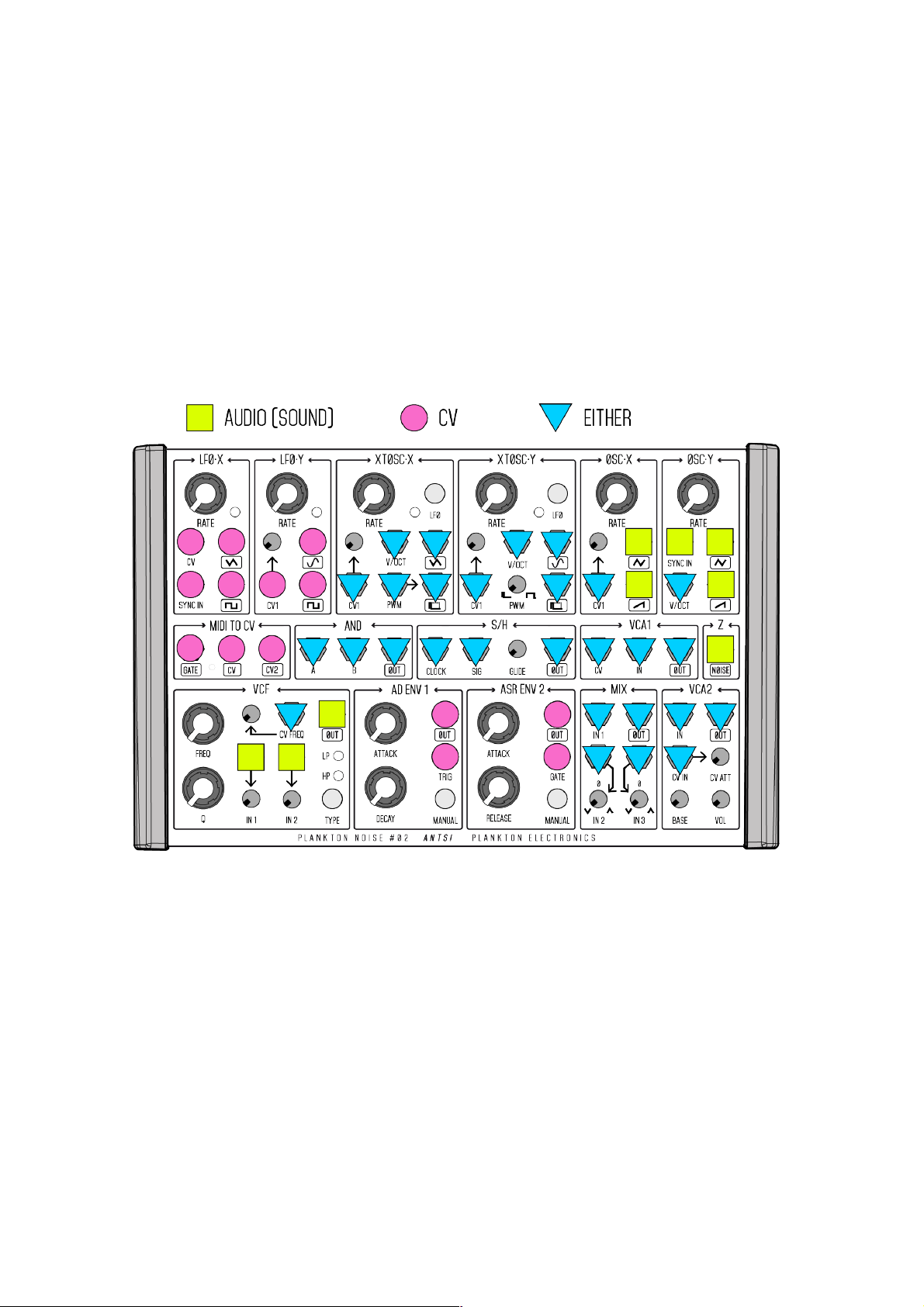
some with both. Use this diagram as a reference:
Some notes about this picture:
1. Inputs with the triangle accept audio and CV while outputs can send
either.
2. This is a suggestion, not a 'must do'. This means, for example, that you
can connect a square wave to the AD ENV 1 TRIG and shape it, accepting
and generating audio, but it is not its main purpose.
3. Looking at it you can deduce that we can use sound waves as a CV to
modulate other parameters. We will see this later.
12
NORMALLED SYSTEM
ANTS! is pre-patched (normalled). This means some connections are already
made in order to play it as a standard mono-synth.
The pre-patched system is as follow:
As you can see the MIDI TO CV outputs are not normalled to the oscillators
CV inputs, so unless you connect a cable from the MIDI TO CV outputs to
the oscillators CV inputs the pitch of the oscillators will not vary. This way
you can choose different configurations, e.g.: CV to both oscillators to play
octaved or unison sounds; CV to XTOSC·Y and CV2 to OSC·X to play
different tones through the VCF and the VCA (paraphony); and a large etc.
You can break any of the normalled routes by connecting a cable at the input
(destination) of the normalled connection. By connecting a cable at the output
you are splitting the signal, so you can use it to another destination, but the
normalled connection remains the same.

13
This is how a normalled connection works:
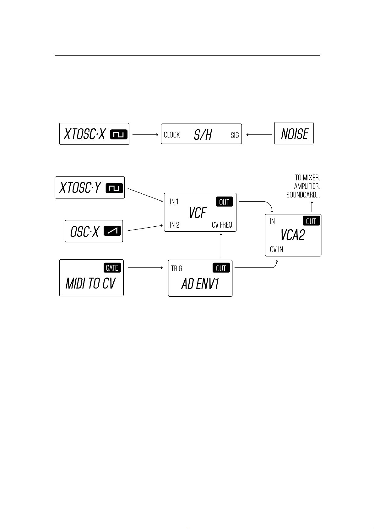
This is the normalled system viewed on the synth :
This is the normalled system in text mode:
XTOSC·Y square wave >> VCF in1
OSC·X saw wave >> VCF in 2
VCF out >> VCA2 in
MIDI TO CV gate >> AD ENV1 trig
AD ENV1 out >> VCF cv freq + VCA2 cv in
Z noise >> S/H sig
XTOSC·X square wave >> S/H clock

14
MIDI
ANTS! uses a 3.5mm MIDI input in the rear part. The package includes a
cable which adapts the 3.5mm connector to the standard MIDI DIN
connector.
The 4 DIP switch is used to control 2 functions: the MIDI channel and the
CV2 mode. Switches 1, 2 & 3 are used to select available MIDI channels,
from 1 to 8.
In order to select a specific MIDI input channel follow this guide (some MIDI
keyboards and controllers use the MIDI ch1 as the default one) :
The switch 4 selects the CV2 mode. Switched down, the converter outputs
the note velocity parameter to CV2. Switched up, it sends the second note
(the value of the second note pressed while the first one is still pressed).
This way you can play 2 note chords or phrases.
If you check the normalled system you will see that the MIDI TO CV GATE is
pre-patched to the AD ENV 1 TRIG. This means that when you connect a
MIDI keyboard and play a note, the VCF and the VCA2 will be opened
according to the AD ENV1 settings (if any cable is breaking the prepatched
system). You can also connect the GATE to the ASR ENV 2, or experiment
with other options, for example, connecting it to the AND gate with an LFO
and sending the mixed signal to the envelope.
The CV outs are not normalled anywhere. This means that if you want the
MIDI notes to be used by the oscillators you must patch it before. You can
connect the MIDI TO CV CV to one or more oscillators and play single osc
patches, unison sounds, fifths, chords, etc. Or you can set the CV2 as a 2nd
note mode with the DIP switch and connect it to a second oscillator.
If you choose to use the velocity parameter, you can connect it directly to
the VCF CV FREQ and open and close the filter depending on the velocity.
Even better, you can use the mixer and mix both, AD ENV1 OUT and CV2
and send it to the VCF and the VCA2. Let's see some examples.

15
First you need to tune the oscillators. Set this:
Connect the audio out at the VCA2 and turn up the volume carefully. You
will hear both oscillators, XTOSC·Y and OSC·X, at the same time. Tune them
so they have the same pitch. Try to set it as CCW as possible.
Patch the MIDI cable to the MIDI IN and set the MIDI channel. When you
press a note you should see the led next to the GATE label blinking along the
note ON and OFF. Set this patch:

16
The oscillators pots should be at the same position that when you tuned it.
When you play a note you should listen both oscillators in unison mode. In
order to have both oscillators in tune, play low (bass) notes on the MIDI
keyboard. Turn full CCW the VCF IN1 pot and listen the difference between
the single osc and two oscs in unison mode. Next, tune the oscillators so
OSC·X is 1 octave over XTOSC·Y and play it. Repeat the process tuning it by
fifths, thirds and other musical intervals. Take your time to play.
Now tune the oscillators to the same note again. Disconnect MIDI TO CV CV
from OSC·X and connect MIDI TO CV CV2 to OSC·X CV1. Set the MIDI switch
4 to its up position (2nd note). The patching should be:
MIDI TO CV CV >> XTOSC·Y V/OCT ; MIDI TO CV CV2 >> OSC·X CV1
You will be able to play two notes. As you will see the gate will be only
opened by the first note. When you press a second note while the first one
is pressed, the 2nd note value will control the OSC·X. (You will make the
most of this feature by connecting a MIDI sequencer instead of playing it
manually and/or with complex patches.)
Now set the MIDI switch 4 to its down position (velocity). Patch this:
Play the MIDI keyboard. With this setup the velocity (the pressure that you
make to each key) will control the filter opening. Set the VCF controls to
your taste. You can also use the mixer MIX to the AD ENV1 OUT with the
MIDI TO CV GATE to play it with more expression. Experiment with different
values.

17
NOTES ON THE MIDI TO CV
1. The GATE out works with logic values. 0 (off) or 5V (on).
2. The CV outs have a resolution of 7bit each and they work from 0 to 5V.
3. The CV outs work with the standard of V/oct. They will output 1V for each
octave played (on CV2 out this is only when it is set the 2nd note mode).
Nowadays, the V/oct is the standard used by the vast majority of oscillators.
4. The MIDI note conversion goes from note 36 (0V) up to 96 (5V), giving a
total of 5 octaves. Below note 36 the converter will output the last note
played and no GATE signal at all, but the MIDITOCV led will blink to show
that the right channel is selected.
5. The oscillators will respond fine on the low range. Playing the highest two
MIDI octaves will result in a bad tracking (MIDI note to pitch). Use them to
elevate the pitch out of its natural range, not for playing melodies.
6. The provided MIDI cable converts the MIDI DIN 5 to a 3.5mm MIDI
connector. If the cable is too short you just need to connect it to a MIDI
female-female adapter or a female-male extender cable. They are available
at most of the music stores.
OSCILLATORS
Oscillators are the main functions of a synth. They are in charge to generate
the sound waves. ANTS! Provides 4 analog triangle core oscillators (the term
‘triangle core’ refers to the electronic design of the oscillators). There are 4
analog oscillators: XTOSC·X, XTOSC·Y, OSC·X and OSC·Y.
The 4 oscillators have V/oct inputs, so all 4 can be played musically if you
connect the MIDI TO CV outputs to them.
18
XTOSC·X and XTOSC·Y have V/OCT inputs plus an extra CV input with an
attenuator (CV1). Both inputs will affects the RATE parameter of the
oscillator. The CV1 IN can be used in many ways. For example you can use
an LFO to modulate up and down the tone. The attenuator will control the
amount of modulation applied to the pitch. We have seen this in the
“BASICS” section of this manual. The V/OCT inputs will transform each volt
in one octave (twice the frequency) so you can connect the outs of the MIDI
TO CV converter here and play the oscillators musically. Again, we have
done it in the “MIDI” section.
OSC·X and OSC·Y only have 1 CV input. In OSC·X you will need to turn up
the attenuator fully CW in order to use the V/OCT feature. In OSC·Y Y there
is no attenuator. If for any reason you want to modulate this oscillator and
attenuate the modulation signal, you always can use the mixer to do it. Just
think that you have another 3 oscillators to do that.
XTOSC·Y and OSC·X are already prepatched to the VCF, but XTOSC·X and
OSC·Y are not patched anywhere. If you want to play 4 osc patches (we
encourage you to do it!) use the mixer. Set this patch and play:
Before setting the patch, tune the 4 oscillators to your taste. For example
XTOSC·X, XTOSC·Y, and OSC·X at the same tone and OSC·Y one octave over
them.

19
Notice that XTOSC·Y is normalled to the VCF IN1 so you do not need to
patch it. If you have done it properly, you should be listening a fat bass
sound.
You may have noticed that going too up on the MIDI keyboard the oscillators go
out of tune between them. This is normal with these kind of oscillators. You can
play them on tune over 2 (maybe 3) octaves, but when played all together the
difference is more noticeable. Try to play over a short range and tune them close
to this range. Best results are obtained playing the keyboard close to the MIDI
note 36. At high pitches the tuning will be worst, if you want to play the synth
with a MIDI keyboard do it on the bass range.
WAVES
The 4 oscillators have different waves at the output. These are sine wave,
triangle wave, pulse (and square), and saw tooth.
Sine waves have no harmonics. They only have the main frequency.
They are best used to generate drums or mixed with other waves to create
complex tones. They are also very useful to be modulated by other waves.
Triangle waves are very close to the sine waves but they have some
overtones. They are made up of odd number harmonics that decrease
exponentially. They are useful for drone sounds and complex auto
generative patches.
Square waves are very rich in harmonics and have a “hollow” sound.
Like the triangle they are made up of an odd number of harmonics but they
decrease steadily. They are very good to filter with the VCF.
You can obtain 2 square waves from the XTOSC·X and XTOSC·Y. XTOSC·X serves
it directly when nothing is plugged in the PWM IN. On XTOSC·Y you can get it
when the PWM pot is at its centre position.
Pulse waves are depend on the Pulse Width (PW). The PW is the
period when the wave is “up” and it is expressed in %. In a square wave the
pulse width is 50%. A Pulse Wave of 10% sounds the same than a 90% (they
are the same wave, but inverted). As the Pulse Width deviates from 50%, it
sounds increasingly brighter and richer; but as the Pulse Width becomes
very narrow, it becomes more thin and nasal. They are made up of all
harmonics, but they amplitude depends on the pulse width percentage.
You can determine the pulse width of XTOSC·Y by turning the “PWM” (Pulse
Width Modulation) pot. Fully CCW it will have a very narrow “up” state and
thin sound. Fully CW it will go far to its limits and will only output a 4V DC

20
voltage (no sound at all). You can use this feature for some complex
patching.
On XTOSC·X, you can modulate the PW by connecting a wave (or any other
signal) to PWM IN. Experiment with LFOs, OSCs, envelopes, S/H, etc. The
results can be very interesting. Tip: attenuate the modulation signal by
inserting it to the mixer before going to the PWM IN.
Saw tooth waves are very rich and bright. They have all the
harmonics and they decrease steadily. They are very good to be filter with
the VCF and produce all kind of sounds. Form classic basses and leads to
complex patches.
OSC or LFO?
Both XTOSC·X and XTOSC·Y have a button which is named “LFO”. When up
the oscillators will work like a normal oscillator, starting at 20Hz. When
down, they will work as an LFO (Low Frequency Oscillator). This means that
instead of sound, they will output something that is below and only used to
modulate other signals like oscs. The led will blink at each pulse “up”. This
way the synth can have 2 LFOs + 4 OSCS; 3 LFOs + 3 OSCS or 2 LFOs + 4
OSCS .
SYNC IN
At OSC·Y there is an input labelled as SYNC
IN. This refers to the osc synchronization.
When another wave is connected here the
triangle core of the OSC·Y will be reseted
each time that the MASTER wave (the one
that goes to the SYNC IN) is negative. This
is a very rare kind of synchronisation
offered by the ANTS! oscillators. You will
see it more clearly here (this is an
oversimplification of what happens inside
the oscillator. Use an oscilloscope if you
want to study it properly):
As you can see each time that the MASTER
osc goes down, the SLAVE (synced) osc is
blocked. When the MASTER oscillator goes
up the triangle wave starts again (always at
the same starting point).
The resulting wave has the period (main

21
tone) of the MASTER wave but with many added harmonics from the
SLAVE (OSC·Y). This can be used in many ways. Creating a cool and very
known resonance-like effect and another weird sounds and timbres. Let’s
see a basic patch where you can start to experiment with.
Set this patch. As usual, connect your mixer to the VCA2 OUT:
Follow these steps:
1. Leave XTOSC·Y fully CCW and OSC·Y fully CW (as in the drawing). Now
turn CCW OSC·Y and listen to.
2. Set XTOSC·Y RATE in another position and repeat step 1.
3. Leave OSC·Y at different fixed positions and move XTOSC·Y.
4. Change the XTOSC·Y PW.
5. Now connect your MIDI keyboard and patch MIDI TO CV CV OUT to
XTOSC·Y V/OCT and play notes. Try different OSC·Y positions.
6. Now connect the MIDI TO CV to OSC·Y instead of XTOSC·Y and play.
Listen to the difference.
7. Listen to the saw output.
8. Modulate the oscillators with LFOs.

22
9. Patch the synced wave from OSC·Y to the VCF IN1 and play the synth like
in the normalled mode.
10. Think, try combinations and enjoy.
FREQUENCY MODULATION
Instead of modulating the oscillators with voltages we can modulate them
with other sound waves. This is better known as frequency modulation or
FM. With FM we use one or more sound waves to modulate an oscillator.
The resulting wave is a resonant, usually metallic timbre. Set this patch:
LFO·Y should be triggering AD ENV 1 and producing a rhythmic sound to
the VCA2 OUT. OSC·X modulates the frequency of XTOSC·Y. Now try
different RATE positions from both oscillators. See how the XTOSC·Y CV1
attenuator affects to the resulting sound. Experiment from here!
XMODULATION
Do you like chaos? Cross-Modulation is a term used when two or oscillators
are modulated between them. If you have looked at the last patch of the
“ANTS! Demo Reel” on youtube that’s is exactly how it sounds.

23
Starting from the last patch, connect the XTOSC·Y PULSE OUT to the OSC·X
CV1. Turn both attenuators fully CW . Now each oscillator modulates each
other. Do you like it? Then try adding another oscillator to the chain. Instead
of A to B and B to A try: A to B, B to C and C to A. Do you want to try it with 4
oscillators? And adding an LFO? Filtering it? Enjoy.
NOTES ON OSCILLATORS
1. The outputs of the oscillators range between +/-4V to +/-5V.
2. You do not need to use the MIDI TO CV converter if you want to play it
musically. Some keyboards and sequencers already have CV outputs.
Connect the CV outs of these machines to the V/OCT inputs.
3. ANTS! has 4 analog V/OCT oscillators in a very compact package. This
means that there have been some compromises. The most evident is that
the tune will be OK over 2 octaves. On the high pitch range the tune will be
worst. Do not expect more on this machine. If you want to play a Bach
suite over a 7 octave keyboard this is not your synth!
4. 4 oscillators give you a whole palette of sounds and possibilities.
However, we think that the synth sounds very nice also with a single osc
over the filter. You have a whole world in this machine. And we will say once
again: explore it!
5. You can combine waves from the same oscillator in the VCF mixer. Look
at the wave drawings at the synth panel for reference. Note that the
position of the wave will determine the resulting mixed wave. For example:
if you mix the 2 waves of the XTOSC·Y the sine wave will not be added to
the square. As it is inverted the resulting wave will be the square wave
without the fundamental. An interesting kind of high pass filtered square
wave. Try different combinations.
LFOS
LFOS (Low Frequency Oscillators) work exactly the same as standard
oscillators, but below the audible range. Both offer Square waves (50% of
PW), LFO·X have tri wave and LFO·Y sine wave. Instead of an attenuator
LFO·X has a SYNC IN which works exactly the same way as OSC·Y.
We will not stop here. If you have understood the oscillators you should not
have any problem with this 2 (2 to 4) functions. Don’t disregard them. They
are very useful and can be powerful tools. Some tips:

24
Use the square wave to trigger the AD ENV 1 (we have done it before);
modulate between them (xmodulation) and use the output to modulate an
oscillator, modulate them with the envelope outputs; use the triangle and
sine waves to modulate slightly the oscillators and detune them, use them
to modulate the VCAs and the VCF to create movement, …
VCF
Many people say that the VCF (Voltage
Controlled Filter) is the soul of a synth. It may
be excessive, but not without a reason. Each
filter have its own character and shapes the
waves in very different ways. The ANTS! VCF
is a not an exception: Analog, resonant,
modular, low pass and high pass, with
overdrive and a built-in mixer.
FILTER BASICS
A filter is used to remove frequencies. The FREQ (frequency or CUT-OFF)
determines the position in the harmonic spectrum where the filter will
begin to filter. A Low Pass Filter will filter (block) the high frequencies while
a High Pass Filter will block the low frequencies. In a VCF we can control the
frequency with an external voltage, hence the name “Voltage Controlled
Filter”.
As you can see in the drawing the filter start to filter the frequencies
starting from the FREQUENCY or CUT-OFF point. Before it there is the Pass
Band, where all the frequencies are sounding. The Transition Band is the
zone where the frequencies are removed gradually. This rate is called the
slope, which is measured in decibels per octave. The VCF has 12db/oct in
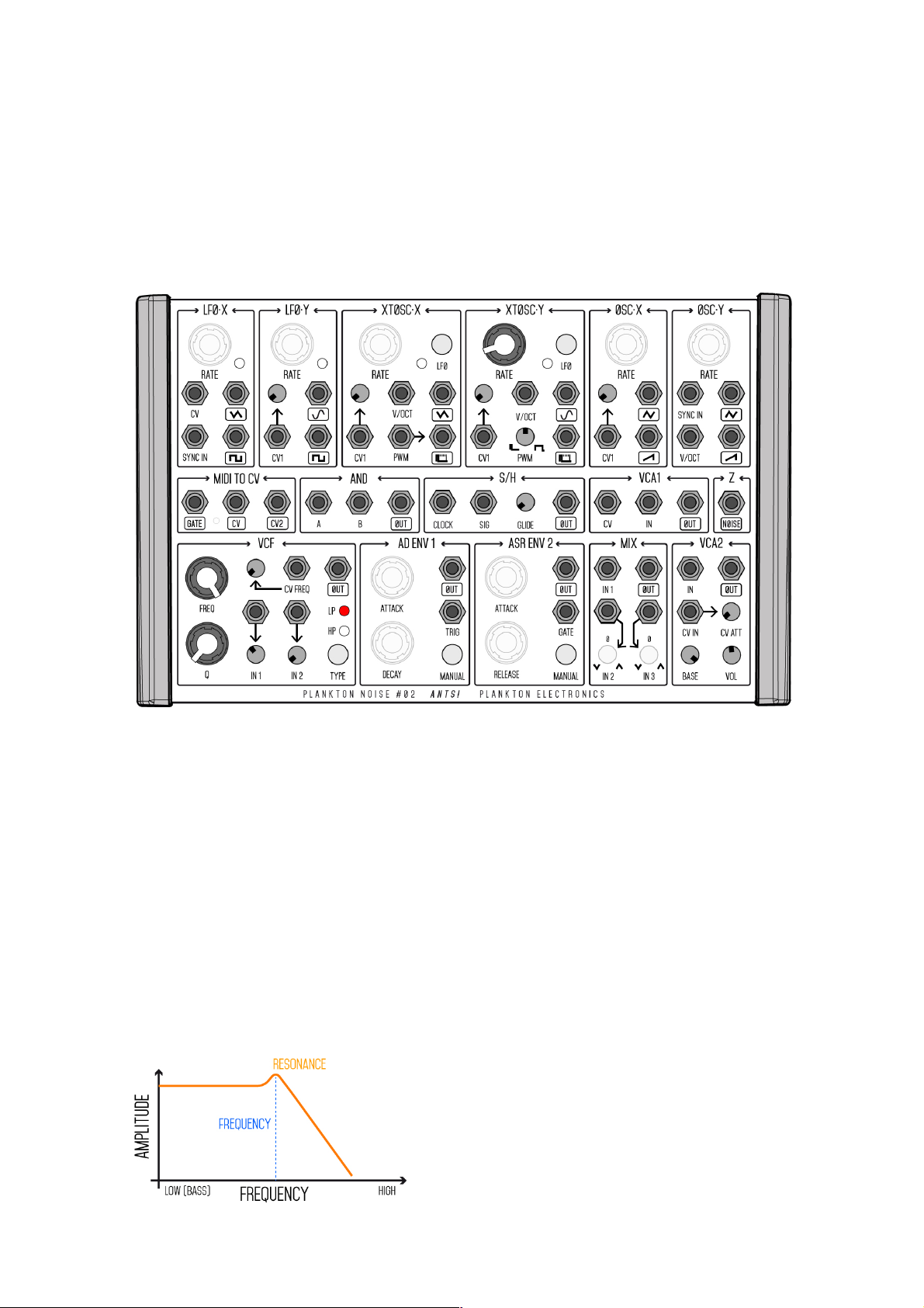
25
the LPF and a 6db/oct in the HPF. This means that in the HPF the
frequencies are reduced more gradually. The Stop Band is the zone where
all the frequencies have been removed.
Using waves rich in harmonics is the best way to use the filters as we will
remove harmonics and shape the waveforms. Let’s see it. Set the next
patch:
Connect the mixer to the VCA2 OUT as usual. Note that XTOSC·Y is
prepatched the VCF IN1 so you should be listening an unfiltered square
wave. Turn the FREQ pot CCW and listen how the harmonics are removed.
Now press the TYPE button and switch it to HPF. Turn the FREQ pot CW and
listen.
Now turn the Q pot fully CW. Move the FREQ pot and hear how it affects the
sound. This Q is the RESONANCE. Turn the IN1 pot at different positions and
hear how the resonance has a different behaviour. Experiment with
different values and waves. Repeat the process connecting the NOISE
output to the IN1. Noise has all the frequencies sounding randomly, and it is
a good reference to listen a VCF.
Resonance occurs when sound in the pass
band near the cut-off frequency is sent
back into the filter as it comes out,
creating feedback. The amount of
feedback affects the volume of these

26
frequencies, as well as the timbre of the sound.
The ‘classic’ way of modulating a filter is using an envelope to open and
close it, creating the effect of a sound rich in harmonics at the beginning
which fade out at the same as the envelope goes down. The AD ENV 1 is
already patched to the VCF CV FREQ IN.
Now set the first patch of this manual. You can find it in the FIRST STEPS
section. If you like you can connect an square wave from an LFO to the AD
ENV 1 to play it automatically. Trigger the AD ENV 1 and see how the VCF is
affected by the modulation and how it shapes the sound.
Change all the filter parameters and experiment. Try first with the FREQ pot
and the CV FREQ attenuator. Small changes in these two potentiometers
will affect the shape of the sound a lot . Try middle and extreme settings.
Change the values of the AD ENV 1 potentiometers also. Make the sound
longer and turn the ATTACK pot CW.
Now experiment with the VCF built in mixer. Turning the IN 1 pot fully CW
will be overdrive the input. This kind of saturation will be more evident
depending on the wave used. Try different parameters. If you want a clean
sound leave the mixer pots in the half position. The resonance will be also
affected by the amount of signal in the input section. If the mixer
potentiometers are fully CW the resonance will have a little effect. By the
other side if the potentiometers are fully CCW the VCF will self-oscillate at
maximum Q, creating a pure sine wave.
Note that the AD ENV 1 will affect the VCA2 also. If you want to listen how the
envelope only affects the VCF, in the VCA2 turn the BASE pot fully CW and the CV
ATT fully CCW.
Some tips and exercises to experiment with the filter:
1. Try different waves at the input. Note that the inputs are prepatched to
XTOSC·Y and OSC·X square and saw tooth waves respectively.
2. Modulate the FREQ with different signals. Try LFOs, sound, noise, S/H.
3. Connect the output of the VCF to one of its own inputs.
4. Connect the output of the VCF to the CV input.
NOTES ON THE VCF
1. LPF is 12db/oct and HPF is 6db/oct.
2. Hot signals in the input will overdrive the input.
27
3. The VCF is in the middle of the normalled system path. All its connections
are already prepatched. Check the normalled schematic and remember that
you always can break these connections.
4. It has a lot of character. Small changes on its settings can affect the
sound in a big way. Experiment and be familiarized with it.
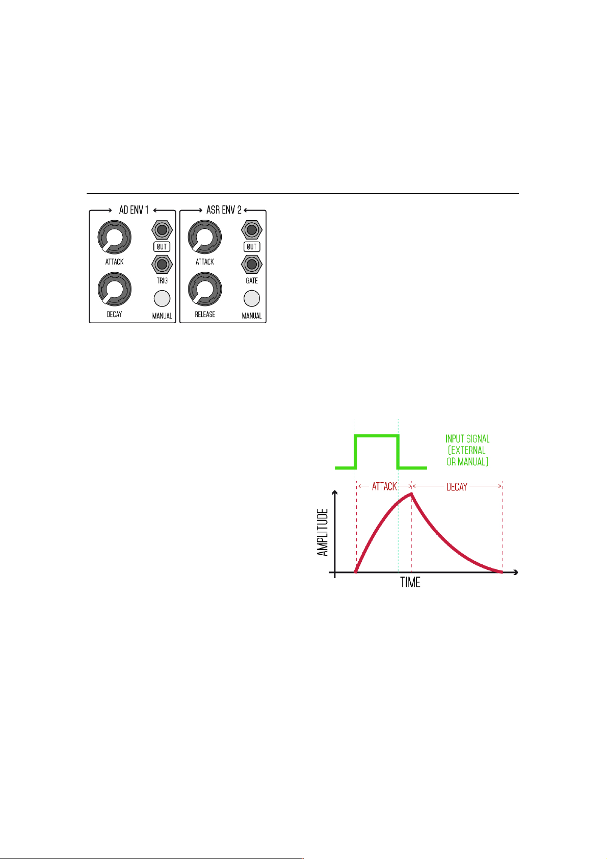
ENVELOPES
Envelopes are one of the main modules
that any synth must have. They are used
to modulate the VCF and VCA and shape
the sounds. ANTS! Offers two envelopes:
AD ENV 1 is a triggered ATTACK - DECAY
envelope and ASR ENV 2 is a gated
ATTACK - SUSTAIN - RELEASE env.
Envelopes generates a raising and falling voltage. In the AD ENV 1 the
sequence is triggered. This means that when it receives a positive signal
(+3V) at the TRIG IN the voltage will raise up until its top (9V) and then it will
go down until the 0 point (somewhere
below but close to 0V). The raising
time is set by the ATTACK pot. The
falling time is set by the DECAY pot.
The time of the sequence is not
dependant of the triggering signal.
The envelope will start when the
input signal goes from 0 to any
value over 3V. (In practice this ‘3V’
means that most of the modules can
trigger the envelope).
In the ASR ENV 2 the sequence is gated. This means that the attack will go
up while the input signal is positive (+2V). When it arrives to its maximum
it will hold (SUSTAIN) until the GATE signal is 0 again. At this point the
RELEASE will do its job. Note that if the GATE signal is shorter than the
ATTACK time it will not develop until to its maximum value and the release
will start from that point.

28
See the 2 situations:
By default ANTS! will use AD ENV 1 as a main envelope. If you have followed
the manual until here, you will have used the AD ENV 1 a lot. If you want to
experiment a bit more set the first patch of the manual and play it with
different values. The envelope will affect the VCF and the VCA2 at the same
time. The attenuators of the CV inputs will determine the amount of
modulation applied to each module. To test the ASR ENV 2 patch this:
As you may have deduced this is the same patch as the first one, but we
have connected ASR ENV 2 in place of AD ENV 1 breaking the normalled
connections of the AD ENV 1. Experiment with the behaviour of this

29
envelope. Set the 2 pots at its minimum position and press the button.
While you have the button pressed the sound is ‘ON’. When you release the
button the sound is ‘OFF’. You’re using a fast ATTACK and RELEASE times and
the SUSTAIN is the main player here. No turn the RELEASE CW and listen. Do
the same with the ATTACK pot.
There are many ways to use the envelopes on ANTS!, not only in the VCF
and VCAs. Some tips:
1. MIX both in the mixer and get a full ADSR envelope.
2. MIX it but invert the ASR in order to create rhythmic patterns. Trigger
them at the same time.
3. Use the AD ENV 1 for the VCF and the ASR ENV 2 for the VCA2 in order
to design more detailed sounds.
4. Use them to modulate the LFOs.
5. Use them to modulate the oscillators.
6. Use one of them with the VCA1 with an oscillator and send the resulting
signal to the VCF.
Create a bass drum with this simple patch:
The AD ENV 1 is modulating the XTOSC·Y tone and the VCA2. The tone of
the oscillators starts up with a very short ATTACK and then goes down,

30
recreating the classical electronic bass drum. There are 3 main parameters
that will affect the drum sound: RATE, CV1 Atten and DECAY. Small changes
here will change the drum sound completely. Try to use different waves and
the VCF. See what happens when you turn the ATTACK pot CW.
NOTES ON THE ENVELOPES
1. AD ENV 1 is a fast envelope. Very useful to create clicked and aggressive
sounds like basses and drums when a short ATTACK is needed. ASR ENV 2 is
slower. Best used for softer and long attack sounds
2. AD ENV 1 goes slightly below 0V when it is relaxed. You may notice it
when you connect it to some modules.
3. You can shape a sound wave by plugging it to the TRIG or GATE ins. Turn
completely CCW all the pots. Now turn one of them slightly CW and see the
result. You can listen the envelope.
VCAS
The VCAs (Voltage Controlled Amplifiers)
are usually used at the final stage of a
synth and they are in charge of control the
amplitude (volume, level) of the sound.
ANTS! has 2 VCAs and both can manage
audio and CV signals. VCA2 is more
complete and more often used as the
output module of the synth.
The VCAs receive an input signal which is processed according to the
control voltage (CV IN). In the next drawing you can see how a sine wave is
processed by the VCA with a short ATTACK and
long RELEASE envelope. We have seen it many
times with the examples. If you want to try it
again set the first patch of the manual and play
the sound. The AD ENV 1 is in charge of
controlling the VCA. The sound will fade in and
fade out depending on the AD ENV 1 settings.
The VCA1 has only 2 inputs and 1 output. The IN
is for the signal to be processed, the CV is for the
controlling signal. The VCA2 has 3 extra
potentiometers: like in other modules, CV ATT is in
charge of controlling the amount of modulation
that controls the function; BASE is a constant

31
voltage that is summed to the CV IN. It is used to open the sound constantly.
Turn it CW to see how it affects the sound. VOL is used like a volume control
at the final stage. As VCA2 is usually used as the final module in the synth
this control helps to set a proper volume to feed the mixer, the FX unit or
the processor that will follow the synth.
AMPLITUDE MODULATION
Like in the FM, instead of modulating the VCAs with voltages we can
modulate them with another sound waves. This is better known as
amplitude modulation or AM. With AM we use one or more sound waves to
modulate the VCA. The resulting sound wave is something similar to the FM
waves. Set this patch:
XTOSC·Y is modulating the VCA2 ON and OFF at audio rates. The saw wave
from OSC·X is being modulated by the VCA2. Try different RATE settings on
the oscillators, try different waves, try to open the BASE knob and listen to
the result. Switch the XTOSC·Y to LFO mode and see how the VCA2 is
modulated by CV signal.
Tips / exercises for the VCAs:
1. Use the VCA1 to produce an AM sound. Then patch it to the VCF and play
it like a common oscillator.
2. Connect an LFO to the VCA1 IN and the AD ENV 1 to CV. Use the resulting
signal to modulate one of the normalled oscillators and play it.
32
3. Do the same as in ‘2’ but connect an audio wave instead of an LFO.
4. Connect a AD ENV 1 with short ATTACK and RELEASE to the VCA1 and
trigger it with medium rated LFO. Connect the ASR ENV 2 to the VCA1 CV
with a short ATTACK and a long RELEASE. Connect the output to the VCA2
CV. Play the sound gating manually the ASR ENV 2.
NOISE
ANTS! has a transistor based analog white noise generator. It’s labelled as
‘Z’ and it has only one patch point, the NOISE OUT. This is a +/-5V noise
source. Noise is random, chaos. Its output is normalled to the S/H SIG IN.
You can use it to mix it in many ways. Some tips:
- Mix it with the bass drum patch (on the ENVELOPES section of the manual)
to create a Snare Drum sound.
- Mix it with an oscillator in the VCF mixer to add some dirt to the sound.
- Connect it to the VCA or the VCF CV inputs to ‘noise modulate’ the sound.
- Modulate an oscillator with it to create a ‘tuned noise’ sound.
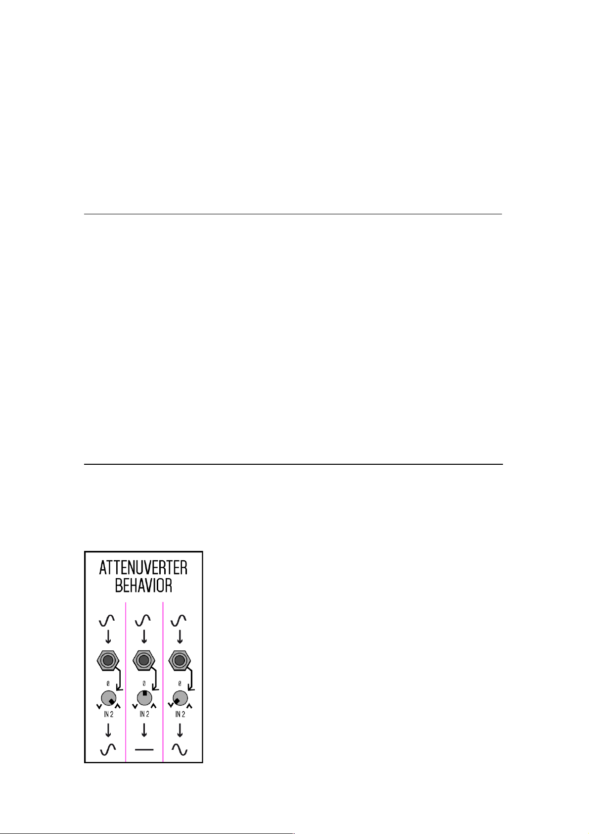
MIXER
There is simple 3 input mixer, MIX, incorporated in the synth. IN1 is goes
directly to the mixing section. IN2 and IN3 goes through an attenuverter and
then to the mixing section. Despite the fancy name an attenuverter is
simple device. When it is in the centre position the signal is 0. If you turn it
CW the signal will be added to the mixing section
normally. But if you turn it CCW the signal will be
inverted. The positive voltage will be the negative
and vice versa. This way you can mix sound waves
and CV signals in many ways. You can also use it as a
simple attenuator by using only 1 of the inputs (for
example to attenuate the signal that will modulate
the XTOSC·X PWM IN). mix different waves and
control voltages in to it to see the results yourself.
TIPS:
1. Use the MIDI TO CV CV2 with the velocity mode.
Mix the CV2 and the AD ENV 1 here and send the

33
resulting signal to the VCF and the VCA2 CV inputs. You will be able to play
expressive sounds while maintaining the curve of the envelope.
2. Some waves of the oscillators are inverted. If you mix directly in the VCF
mixer you will subtract one from another. Inverting one of them here will
have the contrary effect. So you can add the main tone to an square wave
by mixing the inverted sine wave with the square here.
SAMPLE AND HOLD
This is probably one of the most enigmatic functions to the synth newbie.
But the Sample and Hold, S/H, is not that complex to understand. As it
names says the S/H samples a signal and holds it.
The CLOCK input determines the rate at
which the S/H will sample the signal.
The SIGNAL input is the signal that will be
sampled. At each clock pulse the S/H
retains the value (an analog voltage) and
sends it to the output until the next
pulse comes in. The S/H can work at
audio or CV rates.
The GLIDE will add a slope between each
step at the output.
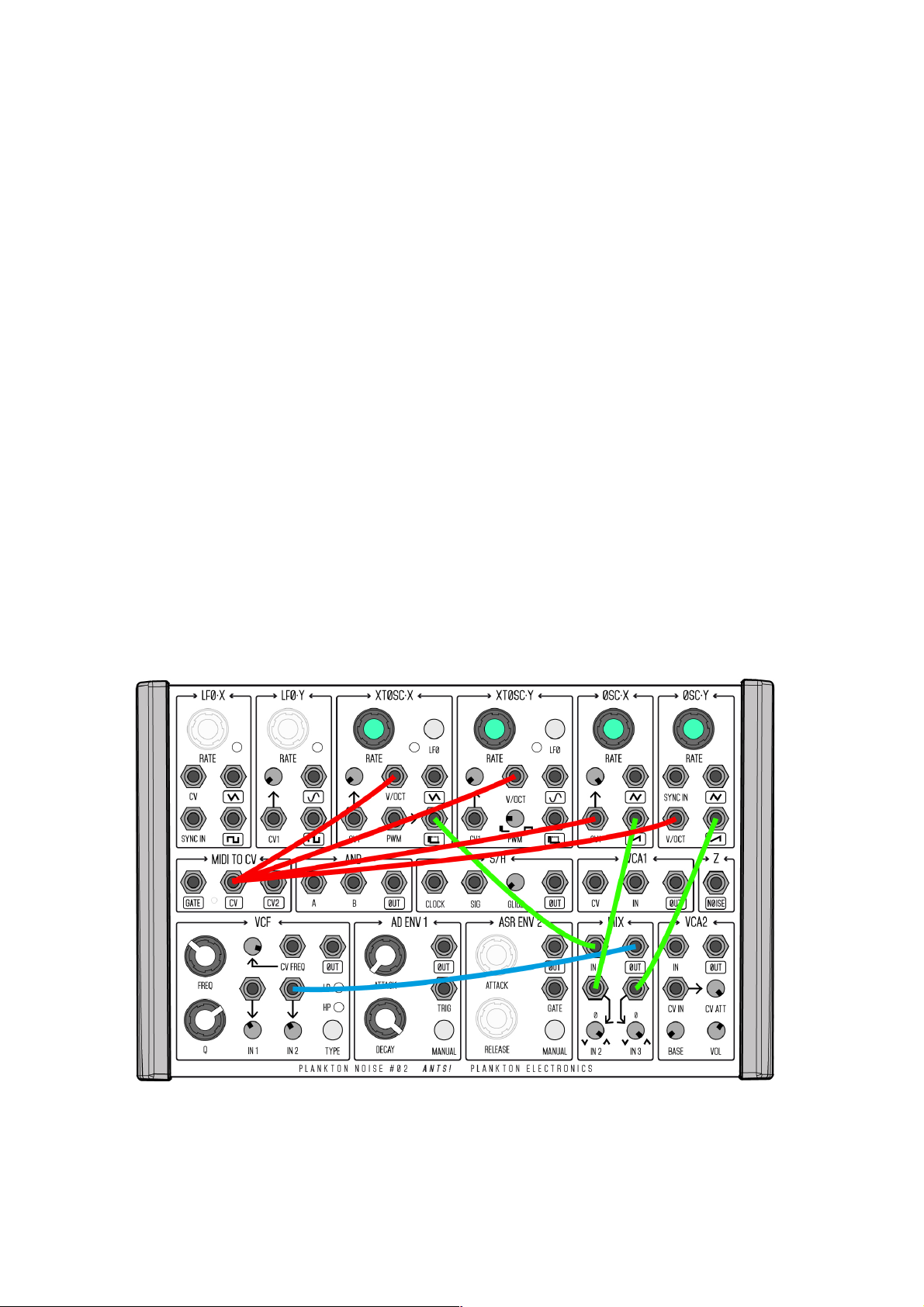
Set this patch:

34
You should listen how the XTOSC·Y tone goes up and down in a stepped
pattern. The S/H is clocked by the LFO·Y and the LFO·X triangle wave is the
signal to be sampled. At each LFO·Y step the S/H takes the current voltage
of the LFO·X and sends it to the XTOSC·Y. Now change the RATE of the
LFO·Y an see how each step is shorter or longer. Change also the LFO·X
RATE. Turn the GLIDE CW and listen how each step is smoothed with a
slope.
Now switch the XTOSC·X to the LFO mode and disconnect LFO·X and LFO·Y
from the patch. You should be listen XTOSC·Y being modulated by random
voltages. This is because the NOISE is normalled to the S/H SIG and the
XTOSC·X square wave to the S/H CLOCK. This generates random stepped
voltages. Change the clock rate and experiment with different values.
But the S/H can also work at audio rates. Switch the XTOSC·X to oscillator
mode and connect the S/H OUT to the VCF IN 1. Now turn up and down the
XTOSC·X RATE. You should listen a dithering effect in the noise, like a digital
sound. This is very close to a low resolution digitalization. The clock rate is
lower than the processed signal so we listen a lot of (great) artefacts.
Tips:
1. Experiment with different oscillator waves. MIX them through the S/H.
2. Connect a microphone to a preamp and connect it to S/H SIGNAL. Use an
oscillator as a clock source and play it with the MIDI keyboard.
3. Process envelopes, LFOs and any kind of signal with the S/H.
NOTES ON THE S/H
1. The S/H can work at CV and audio rates. At a very slow clock rates you
may feel how the CV falls down. This is a compromise in order to be able to
use it at audio rates.
2. The clock input will accept any kind of signal. It will ignore the negative
part of the signal an will take only the positive one. It will start to work over
3V.
3. If you use the GLIDE function at audio rates you will notice how it filters
the sound like in a LPF.

35
AND GATE
The AND gate function is a basic digital logic gate . It works with logic or
digital values: HIGH and LOW (or ‘0’ and ‘1’). Anything below 3V will be
considered a ‘0’ while anything over it, a ‘1’. In practice the output is HIGH
only when the 2 inputs are HIGH:
A B OUT
LOW
LOW
LOW
LOW
HIGH
LOW
HIGH
LOW
LOW
HIGH
HIGH
HIGH
The AND function have many uses. It can work with audio or CV signals. You
can combine both. Set this patch:
Now you should be listening a digital like sound. Both oscillators are being
mixed through the AND gate. Try with different values and see how the
sound changes.

36
Tips:
1. Combine LFOs instead of oscillators to create rhythmic patterns.
2. Combine an LFO and an oscillator to create gated effects.
3. Combine the 2 envelopes. Being AD ENV 1 short and triggered by an LFO
and ASR ENV 2 being gated manually.
4. Connect the MIDI TO CV GATE and an LFO. Connect the output to the AD
ENV 1 TRIG.
5. Pair it with the S/H to create complex patterns.
HACKING
ANTS! Is an open-source machine. We provide the schematics and the MIDI
software for free. You can hack the machine if you like. Inside the synth you
will find an ISP port to update the MIDI firmware and 4 potentiometers to
tune the oscillators.
IF YOU OPEN THE SYNTH DON’T TOUCH ANYTHING IF YOU DON’T KNOW
WHAT ARE YOU DOING. SOME COMPONENTS ARE EASY TO DAMAGE.
ANY MALFUCTION CAUSED BY OPENING THE SYNTH WILL NOT BE
COVERED BY THE WARRANTY.
If you want to open the synth follow these steps:
1. Turn-off the machine. Disconnect the power cable.
2. Remove the side covers. Each cover uses 2 T10 torx screws. When
reassembling the machine don’t over torque these screws. Tighten them
gently until the covers are in place. The screws don’t have an stop point.
3. Remove the 2 front screws. Do the same with the 3 back top screws
(these 3 screws are close to the front panel in the back part). Use a 1/16
Allen key (hex).
4. Separate the panel from the metal case. Be careful here. There are some
2 flat cables inside the unit.
5. Remove the flat cables. Before doing it take a look on its orientation.
Reversing the power cable and powering the unit will damage it instantly.

37
Now you have access inside the unit. Once again: be careful here! The most
important parts are the ISP port to update the MIDI software and the 4 blue
tuning potentiometers.
We will not provide any support on how to hack the unit. Continue at your
own risk. Check the schematics for reference.
The end
Now it’s time to explore the synth yourself and make your sounds and
music with it. We will be happy if you upload your own sounds to the online
patch browser and share it with the community. We will like to see your
own videos playing the synth.
We hope that you have enjoyed this manual. If you have any comments,
remember to send them to support@planktonelectronics.com
Enjoy ANTS! and happy patching!

38
SPECIFICATIONS
MAIN
27 INPUTS, 24 OUTPUTS
ANALOG CIRCUITRY
EURORACK FRIENDLY (VOLTAGE)
MODULES
2 LFOs
4 OSCs (2 switchable to LFO)
MIDI TO CV
AND LOGIC GATE
SAMPLE AND HOLD
2 VCAs
WHITE NOISE GENERATOR
LP/HP VOLTAGE CONTROLLED FILTER
1 TRIGGERED A/D ENVELOPE
1 GATED A/S/R ENVELOPE
1 MIXER WITH ATTENUVERTERS
MATERIALS
ROLLED STEEL CASE
PLASTIC SIDE COVERS
FR4 PANEL
SOFT-TOUCH KNOBS
LFOS
+/-4V OUTPUTS
TRIANGLE CORE
TRIANGLE, SINE AND SQUARE WAVES
RANGE: 19SEC – 30HZ
‘SYNC IN’ ON LFO·X
OSCILLATORS
V/OCT INPUTS
+/-4V OUTPUTS
TRIANGLE CORE
TRIANGLE, SINE, SQUARE, SAWTOOTH
AND PW WAVES
‘SYNC IN’ OSC·Y
2 SWITCHABLE TO LFO
PWM IN ON XTOSC·X
PWM KNOB ON XTOSC·Y
MIXER
3 INPUT
2 ATTENUVERTERS
AD ENV1
TRIGGERED ENVELOPE
MANUAL CONTROL
‘TRIG IN’
ATTACK: 0.9msec – 1sec
DECAY: 3msec – 5ec
ASR ENV2
GATED ENVELOPE
MANUAL CONTROL
‘GATE IN’
ATTACK: 5msec – 10sec
RELEASE: 1msec – 4Sec
MIDI TO CV
1-8 CHANNEL SELECT
GATE OUT (NOTE ON)
CV (NOTE) OUT
CV2 OUT (2nd NOTE OR VELOCITY)
VCF
RESONANT ANALOG FILTER
HIGH PASS / LOW PASS
2 INPUT MIXER WITH DISTORTION
VOLTAGE CONTROLLED FREQUENCY
VCAS
2 Voltage Controlled Amplifiers
‘BASE’ and ‘VOLUME’ ON VCA1
AND GATE
2 INPUT LOGIC GATE
0 TO 5V
POWER
12Vac 1A
INCLUDED POWER SUPPLY
 Loading...