


SWP-0412/0420G

SWP-0412/0420G Series L2 Managed Switch User Guide
PLANEX
L2 Managed Switch
SWP-0412G/SWP-0420G
User Guide

Federal Communications Commission Statement
This device complies with Part 15 of the FCC Rules. Operation is subject to the
following two condi tions:
• This device may not cause harmful interference, and
• This devi ce must accept a ny int e rferen ce re ceived in cludin g i nte rfe ren ce
that may cause undesired operation.
This equipment has been tested and found to comply with the limits for a Class
B digital device, pursuant to Part 15 of the FCC Rules. These limits are
designed to provide reasonabl e prote ction aga inst harmful inter feren ce in a
residential instal lat ion. This equipment gene rate s, uses and can r adiate radi o
frequency ene r gy and , i f not installed and used in a c cordan ce wi th
manufacturer's instructions, may cause harmful interference to radio
communications. However, there is no guarantee that interference will not
occur in a particular installation. If this equipment does cause harmful
interferen ce to radio o r television recep tion, which can be de ter mined by
turning th e e quip men t o ff and on , th e u se r i s en cou raged to t ry t o cor re ct th e
interference by one or more of the following measures:
• Reorient or r elo cate the receivi ng an ten na.
• Increase the separation between the equipment and receiver.
• Connect the e quipment to an outlet on a circuit di fferent from that to w hich
the receiver is connected.
• Consult th e deal e r or an e xpe ri en ced radio / TV te chni cian fo r he lp.
WARNING! The use of shielded cable s for conne ction of the monito r to the
graphics card is requi red to assure compliance with F CC regulations. Changes
or modification s to this unit not e xpressly approved by the party responsible for
compliance could void the user's authority to operate this equipment.
Canadian Department of Communications Statement
This digita l a ppar atu s d oe s no t e xceed the Cl a ss B li mit s for radi o noi se
emissions from digital apparatu s set out in the Rad io Interfe rence Reg ulation s
of the Canadian Department of Communications.
This class B digital appa ratus complies with Ca nadian ICES-003 .

SWP-0412/0420G Series L2 Managed Switch User Guide
Table of Contents
1.1 L2 managed features........................................................9
1.2 Conventions used in this document ...............................10
1.2.1 Notations.........................................................10
1.2.2 Typography .....................................................10
1.2.3 Symbols ..........................................................10
2.1 Package contents...........................................................11
2.2 Front Panel.....................................................................12
2.3 Rear Panel......................................................................13
2.4 Technical specifications..................................................14
3.1 Part 1 — Installing the hardware....................................15
3.1.1 Installing the switch on a flat surface..............15
3.1.2 Mounting the switch on a rack ........................15
3.2 Part 2 — Setting up the switch.......................................15
3.2.1 Connect the console port................................16
3.2.2 Connect to the computers or a LAN................16
3.2.3 Attach the power adapter................................16
3.3 Part 3 — Basic switch setting for management .............17
3.3.1 Setting up through the console port................17
3.3.2 Setting up through the Web interface .............20
4.1 Log into Web user interface ...........................................23
4.2 Functional layout ............................................................25
4.2.1 Menu navigation tips.......................................26
4.2.2 Commonly used buttons an d icons.................27
4.3 System Pages ................................................................27
4.3.1 Management ...................................................27
4.3.2 IP Setup ..........................................................29
4.3.3 Administration .................................................29
4.3.4 Reboot.............................................................31
4.3.5 Firmware Upgrade ..........................................31

4.3.6 CPU Usage .................................................... 33
4.4 Physical Interfac e ......................................................... 34
4.5 Bridge............................................................................. 36
4.5.1 Link Aggregation ............................................ 36
4.5.2 Mirroring ......................................................... 38
4.5.3 Traffic Control................................................. 39
4.5.4 Dynamic Addresses ....................................... 40
4.5.5 Static Addresses ............................................ 42
4.5.6 Tagged VLAN................................................. 43
4.5.7 Default Port VLAN and CoS........................... 45
4.5.8 CoS Queue Mapping...................................... 46
4.6 SNMP............................................................................. 47
4.6.1 Community Table ........................................... 47
4.6.2 Host Table...................................................... 48
4.6.3 Trap Setting.................................................... 49
4.7 Security.......................................................................... 50
4.7.1 Port Access Control........................................ 50
4.7.2 Dial-In User .................................................... 51
4.7.3 RADIUS.......................................................... 52
4.8 VCT................................................................................ 54
4.9 Statistics Chart............................................................... 55
4.9.1 Traffic Comparison......................................... 55
4.9.2 Error Group .................................................... 56
4.10 Save Configuration........................................................ 57
5.1 Power On Self Test........................................................ 59
5.1.1 Boot ROM Command Mode........................... 60
5.1.2 Boot ROM Commands................................... 61
5.2 Login and Logout........................................................... 62
5.3 CLI Commands.............................................................. 62
5.3.1 System Commands........................................ 62
5.3.2 Physical Interface Commands ....................... 65
5.3.3 Bridge Commands.......................................... 66
5.3.4 SNMP............................................................. 72
5.3.5 Security Commands....................................... 76

SWP-0412/0420G Series L2 Managed Switch User Guide
5.4 Miscellaneous Commands .............................................79
6.1 IP Addresses ..................................................................80
6.1.1 Structure of an IP address ..............................80
6.1.2 Network classes..............................................82
6.2 Subnet masks.................................................................83
7.1 Diagnosing problems using IP utilities............................85
7.1.1 ping .................................................................85
7.1.2 nslookup..........................................................87
7.2 Simple fixes ....................................................................88

List of Figures
Figure 1. Front panel..................................................................... 12
Figure 2. Rear panel..................................................................... 13
Figure 3. Login and IP setup Screen ............................................ 19
Figure 4. Login Screen.................................................................. 20
Figure 5. IP Setup......................................................................... 22
Figure 6. Configuration manager login screen.............................. 23
Figure 7. Home page.................................................................... 24
Figure 8. Top Frame..................................................................... 25
Figure 9. Expanded Menu List...................................................... 26
Figure 10. Management.................................................................. 28
Figure 11. IP Setup......................................................................... 29
Figure 12. Administration................................................................ 30
Figure 13. Reboot ........................................................................... 31
Figure 14. Firmware Upgrade......................................................... 32
Figure 15. CPU Usage.................................................................... 33
Figure 16. Physical Interface .......................................................... 35
Figure 17. Link aggregation ............................................................ 38
Figure 18. Mirroring page................................................................ 39
Figure 19. Traffic Control ................................................................ 40
Figure 20. Dynamic Address........................................................... 41
Figure 21. Static Address................................................................ 42
Figure 22. Tagged VLAN ................................................................ 44
Figure 23. Default Port VLAN and CoS .......................................... 45
Figure 24. CoS Queue Mapping..................................................... 46
Figure 25. Community Table........................................................... 47
Figure 26. Host Table...................................................................... 48
Figure 27. Trap Setting ................................................................... 49
Figure 28. Port Access Control....................................................... 51

SWP-0412/0420G Series L2 Managed Switch User Guide
Figure 29. Dial-In user .....................................................................52
Figure 30. RADIUS..........................................................................53
Figure 31. VCT.................................................................................54
Figure 32. Traffic comparison..........................................................56
Figure 33. Error group .....................................................................56
Figure 34. Save Configuration.........................................................57
Figure 35. CLI interface ...................................................................59
Figure 36. Boot ROM Command Mode...........................................60
Figure 37. SYS commands..............................................................63
Figure 38. Using the ping utility .......................................................86
Figure 39. Using the nslookup utility................................................87

List of Tables
Table 1. Front panel labels and LEDs ......................................... 12
Table 2. Rear panel labels........................................................... 13
Table 3. Technical specifications................................................. 14
Table 4. LED Indicators ............................................................... 17
Table 5. Commonly used buttons and icons ............................... 27
Table 6. Boot ROM commands ................................................... 61
Table 7. IP address structure....................................................... 81
Table 8. Troubleshooting............................................................. 88

SWP-0412/0420G Series L2 Managed Switch User Guide
1 Introduction
Congratulations on becoming the owner of the SWP-0412/0420G managed
web smart plus switch! You may now manage your LAN (local area network)
through a friendly and powerful user interface.
This user guide tells you how to set up the SWP-0412/0420G web smart
plus switch, and how to customize its configuration to get the most out of
this product.
1.1 L2 managed features
• 24 1 0/ 100/10 00BASE -TX auto - sensing Fast Et he rnet po rts
• four small form factor (SFP) Gigabit interface converter (miniGBIC) slots
• 802. 1D t ran spa ren t b ri dge / spanni ng t ree p r ot o col
• 8K MAC address cache wi th hardwa re-a ssisted agi ng
• 802. 3x flow cont rol
• 802.1Q-based tagged VLAN, up to 256 VLANs
• 802. 1p cla ss of service, 4 queues per por t
• 802. 3ad li n k a ggre gat ion (manual ) , up to 7 t run k group s
• Port Mirroring
• 802. 1 x and RADIUS
• RM ON: suppo rt 4 groups (1 , 2, 3, 9)
• SNMP v1, v2
• MIB-II
• Enterprise MIB for PSU, fan, and system temperature, voltage
• Tel net remot e login
• FTP for fir mware upda te and configur ation ba ckup
• Command Line Interpreter through console , telnet
• Web GUI
• LEDs for port link status
• LEDs system,

1.2 Conventions used in this document
1.2.1 Notations
• A crony ms are defined t he first time th ey appea r in te xt and in th e glossary .
• For brevity, the SWP-0412/0420G switch is referred to as “the switch.”
• The terms LAN and netwo rk a r e u sed int e rcha nge ably to r e fe r to a g ro up
of Ethernet-connected computers at one site.
1.2.2 Typography
• Italics are used to pr e sent the pa ra mete rs for t he co mman d li ne
interpreter.
• Bo ldface ty pe text is used for items you select from menus and
drop-down list s, and te xt string s you ty pe when p rompted by the progra m.
1.2.3 Symbols
This document u ses t he fol low ing i con s to call y our at te ntio n to spe cifi c
instructions or explanations.
Note
Provides clarification or additional information on the current
topic.
Definition
Explains terms or acronyms that may be unfamiliar to many
readers. These terms are also included in the Glossary.
WARNING
Provides messages of high importan ce, in clud ing mess ages
relating to personal safety or system integrity.

SWP-0412/0420G Series L2 Managed Switch User Guide
2 Getting to know the SWP-0412/0420G
2.1 Package contents
The SWP-0412/0420G switch package comes with the following items:
• S WP-0412/0420G
• AC Power cord
• Null modem cable for console interface (DB9)
• Ra ck installa tion kit (two brackets w ith six # 6 -32 screws)

12
2.2 Front Panel
The front panel includes LED indicators that show the system, , fan, and
port status.
Figure 1. Front panel
Table 1. Front panel labels and LEDs
Label Color Status Description
On Unit is powered on Green
Flashing Self-test, INIT, or downloading
Amber On Abnormal temperature or voltage
SYSTEM
Off No power
Green On Li nk (RJ-45 or SFP) is present; port is
enabled
Flashing Data is being transmitted/received
10/100/1000
port status
Off No Ethernet link
Green On 1000Mbps
Amber On 100Mbps
10/100/1000
port speed
Off 10Mbps or link is not present
Green On full duplex
Amber On half dulplex
10/100/1000
port duplex
Off link is not present

SWP-0412/0420G Series L2 Managed Switch User Guide
2.3 Rear Panel
The switch rear panel contains the ports for the data and power
connections.
Figure 2. Rear panel
Table 2. Rear panel labels
No. Label Description
1 Power Connector Connects to the supplied power cord
2 FAN1 – FAN2 System fans

14
2.4 Technical specifications
Table 3. Technical specifications
Physical Dimensions 43.5mm(H) X 444 mm(W) X 265mm(D)
Input Consumption Power
100-240V AC/2.5A 50-60Hz < 38 watts
Operating Storage
Temperature
0-40℃ 0-40℃
Humidity 35 to 85 % 35 to 85 %
Environmental Ranges
Altitude up to 10,000 ft
(3,000m)
40,000 ft
(12,000m)
Dimensions Voltage and Current Speed: Replaceable Fans
40 x 40 x 20 mm 12VDC, 0.13A 8200RPM

SWP-0412/0420G Series L2 Managed Switch User Guide
3 Quick start guide
This section provide s the basic inst ructions to set up the S WP-0412/0420 G
environment. Refer also to the SWP-0412/0420G Installation Guide.
Part 1 shows you how to install the SWP-0412/0420G on a flat surface or
on a rack.
Part 2 provides instructions to set up the hardware.
Part 3 shows you how to configure basic settings on the
SWP-0412/0420G.
Obtain the following in fo rmatio n fro m y our netw o rk ad ministr ator b e fore
proceeding:
IP address for the switch
Default g at eway for the netwo r k
Network mask for thi s network
3.1 Part 1 — Installing the hardware
Connect the devi ce to the pow er outlet , and your co mpute r or networ k.
3.1.1 Installing the switch on a flat surface
The switch should be install ed on a level surfa ce that can support the wei ght of
the switches and their accessories. Attach four rubber pads on the marked
location on the botto m of the swi t ch.
3.1.2 Mounting the switch on a rack
1. Attach brackets to each side of the switch and make the posts insert to
the switch.
2. Insert and tighten two screws to securely attach the bracket to the rack
on each side.
3.2 Part 2 — Setting up the switch
Connect the devi ce to the pow er outlet , and your co mpute r or networ k.

GigaX Series L2 Managed Switch User’s Guide
16
3.2.1 Connect the console port
For console management, use an RS232 (DB9) to connect the switch. If
you want to use WEB interface, connect your PC to the switch using the
Ethernet cable.
3.2.2 Connect to the computers or a LAN
You can use Ethernet cable to connect computers directly to the switch ports.
You can also connect hub s/switche s to the switch po rts by Ethernet cables.
You can use ei ther the crossove r or straight -through Ethernet cable to co nnect
computers, hubs, or switches.
Use a twisted-pair Category 5 Ethernet cable to connect the
1000BASE-T port. Otherwise, the link speed can not reach
1Gbps.
3.2.3 Attach the power adapter
1. Connect the AC power cord to the POWER receptacle on the back of
the switch and plug the other end of the power cord into a wall outlet or
a power strip.
2. Check the front LED indicators with the description in Table 4. If the
LEDs light up as described, the switch hardware is working properly.

SWP-0412/0420G Series L2 Managed Switch User Guide
Table 4. LED Indicators
No. LED Description
1 System Solid green indicates that the device is turned
on. If this light is off, check if the power
adapter if attached to the switch and plugged
into a power source.
2 Switch ports
[1] to [24]
Solid green indicates that the device can
communicate with the LAN, or flashing when
the device is sending or receiving data from
your LAN computer.
3.3 Part 3 — Basic switch setting for
management
After completing the hardware connections, configure the basic settings for
your switch. You can manage the swi tch using the followin g method s:
• Web i nterfa ce: the switch has a set of pages to allow to you mana ge it
using Java
®
-enabled IE5.5 or highe r version.
• Command Line Interface: use console port to manage the switch.
3.3.1 Setting up through the console port
1. Use the supplied crossover RS-232 cable to connect to the console
port on the back of the switch. This port is a male DB-9 connector,
implemented as a data terminal equipment (DTE) connection. Tighten
the retaining screws on the cable to secure it on the connector.
Connect the other end of the cable to a PC running terminal emulation
software. e.g Hyper Terminal.

GigaX Series L2 Managed Switch User’s Guide
18
2. Make sure the settings of your terminal emulation software as follows:
a) Choose the appropri ate ser ial port number
b) Set the data baud rate to 9600
c) Set the data format to no parity, 8 data bits and 1 stop bit
d) No flow control
e) Set VT1000 for emulation mode
3. After setting up the terminal, you can see the prompt “(PLANEX)%” on
the terminal.
4. Type “login” to access the command line interface. The default user
name is “admin”. Password is “password” <Enter>.
You can change the pas sword at any time throug h CLI (see
section 5.3.1). To protect your switch from unauthorized
access, you must change the default password as soon as
possible.
5. Follow these steps to assign an IP address to the switch:
a) Type “net interface ip sw0 <your ip address> <your network
mask>”. For example, if your switch IP is 192.168.10.1 and the
network mask is 255.255.255.0. Then you should type “net
interface ip sw0 192.168.10.1 255.255.255.0”.
b) If the switch has to be managed across networks, then a default
gateway or a static route entry is required. Type “net route static
add 0.0.0.0 <your network gateway IP> 0.0.0.0 1// as your default
route entry, as shown in Figure 3.

SWP-0412/0420G Series L2 Managed Switch User Guide
Figure 3. Login and IP setup Screen

GigaX Series L2 Managed Switch User’s Guide
20
3.3.2 Setting up through the Web interface
To successfully connect your PC to the switch, your PC must a valid IP in your
network. Contact your network administrator to obtain a valid IP for the switch.
If you wish to chan ge th e de fault IP a dd ress o f t he swit ch, fol low sectio n 3 .3.1
to change the IP addre ss. Since the switch doe s not supp ort DHCP client
function, a v alid stati c IP for the swit ch i s ne c e ssary to u se Web interface.
1. It is not necessary to login Web interface at the first time to use Web
interface because the default configuration for Web access
authentication is enable. To secure the system configuration, please
enable the authentication function at the “Administration” page under
“System” categor y. Skip step 2 if the authentication is disab led .
2. At any PC connected to the network that the switch can access , open
your Web browser (Internet Explorer), and type the following URL in the
address/location box, and press <Enter>:
http://192.168.1.1
This is the fa ctory default IP a ddres s of the swit ch.
A login screen appears , as shown in Figur e 4.
Figure 4. Login Screen

SWP-0412/0420G Series L2 Managed Switch User Guide
Enter your user name and passwo rd, and then click to enter the
Configuration Man ager . Use the follow ing de faults the fi rst time y ou log
into this i nt e rface:
Default User Name: Admin
Default Password: password
You can change the password at any time (see section
5.3.1 System Commands).
3. To setup a new IP address, click “System”, then “IP Setup” (see Figure
8). Fill in the IP address, network mask and default gateway, then click
.
4. If your new address is different from the default, the browser can not
update the switch status window or retrieve any page. This is normal.
You have to retype the new IP address in the address/location box, and
press <Enter>. The WEB link returns.
5. To enable authentication for Web access, click “Administration” on
the menu list, then select “Enabled” to start the protection.
A login win dow a ppe ar s i mme dia tely a fte r you click
. See the
figures on the ne xt pag e.

GigaX Series L2 Managed Switch User’s Guide
22
Figure 5. IP Setup

SWP-0412/0420G Series L2 Managed Switch User Guide
4 Management with the Web Interface
The switch provides Web pages that allow switch management through the
Internet. The program is designed to work best with Microsoft Internet
Explorer® 5.5, or later versions. NOTE: Netscape is not suppo rted .
4.1 Log into Web user interface
1. From a PC, open your web browser, type the following in the web
address (or location) box, and press <Enter>:
http://192.168.1.1
This is th e fa cto ry de faul t IP a dd res s for t he swit ch . A log in sc reen
displays, as shown in Fig ure 6.
Figure 6. Configuration manager login screen
2. Enter your user name and password, then click
.
Use the following de faul ts the first time you log into the p rogram. You can
change the password at any time through CLI interface (see section 5.3.1
on page 62).
Default User Name: admin
Default Password: password

SWP-0412/0420G Series L2 Managed Switch User’s Guide
24
The home page app ea r s each ti me you log into the p rogra m. See Figu re s 1 1
and 12).
Figure 7. Home page

SWP-0412/0420G Series L2 Managed Switch User Guide
4.2 Functional layout
Typical web page consi sts of thr ee separate frames . The top frame ha s a
switch logo a s show n Fi gure 8
Figure 8. Top Frame
The left frame, a menu frame as shown in Figure 9, contains all the features
available for swit ch configu ration. The se feature s are grouped int o catego ries,
e.g. System, Bridge, etc. You can click on any of these to display a specific
configuration page.

SWP-0412/0420G Series L2 Managed Switch User’s Guide
26
Figure 9. Expanded Menu List
The right frame displays configuration pages or graphics for the statistics.
See section 4.3 for details.
4.2.1 Menu navigation tips
• To e xpand a grou p of related menus, cli ck on the cor respondi ng group
name. The
sign will change to after expansi on.
• To con tract a gro up of related menus: cli ck on the correspondi ng grou p
name. The
sign will app ea r ne xt to the g roup na me.
• To op en a specifi c configu ration pag e, cli ck on the desi red menu ite m.

SWP-0412/0420G Series L2 Managed Switch User Guide
4.2.2 Commonly used buttons and icons
The following table describ es the fun ction fo r each button and icon used in the
application.
Table 5. Commonly used buttons and icons
Button/Icon Function
Stores any changes you have made on the current page.
Adds the existing configuration to the system, e.g. a static MAC
address or a firewall ACL rule and etc.
Modifies an existing entry
Modifies the existing configuration in the system, e.g. a static route
or a filter ACL rule and etc.
Deletes the selected item, e.g. a static route or a filter ACL rule and
etc.
Re-displays the current page with updated statistics or settings.
4.3 System Pages
System pages include manage ment, IP setu p, admini strati on, rebo ot, and
firmware upd ate func tion.
4.3.1 Management
The Management page contains t he fol low ing in fo rmation :
Model Name: produ ct name
MAC Address: switch MAC address
System Name: u s e r assign ed na me to ident i fy th e sy stem (e ditable)
System Contact (editable)
System Location (edi tabl e)

SWP-0412/0420G Series L2 Managed Switch User’s Guide
28
To save any changes and make it effective immediately, click
. Use
to refresh the setting , as shown in Fi gure 10.
Figure 10. Management

SWP-0412/0420G Series L2 Managed Switch User Guide
4.3.2 IP Setup
The switch support s dynamic IP and stati c IP assignment. The dyna mic IP is
get from a DHCP server within the same VLAN. The IP Setup page contains
the following e dita ble in fo rmation:
IP Address: assign a static IP addre ss to the switch mana gement
interface.
Network Mask
Default Gatew ay
To save any changes and make it e ffective i mmediately , click
. Use
to refresh the setting, as shown in Figure12.
Figure 11. IP Setup
4.3.3 Administration
The Administrati on page allows you enable o r disable the au thenti cation fo r
web user by password protection.
To save any changes and make it e ffective i mmediately , click
. Use
to refresh the setting, as shown in Figure 12. When you enable the
password pr ote cti on, y ou h ave to login again immedi ate l y.

SWP-0412/0420G Series L2 Managed Switch User’s Guide
30
You can change the password at any time through the CLI
interface.(Please refer to section 5.3.1)
Figure 12. Administration

SWP-0412/0420G Series L2 Managed Switch User Guide
4.3.4 Reboot
The Reboot page contains a button. Clicki ng the but ton reboo ts the
syst em.
Rebooting the system stops the network traffic and
terminates the Web interface connection.
Figure 13. Reboot
4.3.5 Firmware Upgrade
The Firmware page contains the following in formation :
Hardware Version: shows the har dware rev ision nu mber.
Boot ROM Versi on: sh ows th e ve rs ion of the bo ot code
Firmware Version: shows the current running firmware version. This
number will be updated afte r the fi rmware update.

SWP-0412/0420G Series L2 Managed Switch User’s Guide
32
Enter the firmware l ocation into th e firmware spa ce directly , or click
to choose the file name of the firmwar e from pro mpt window. Cli ck
to update the switch firmware. See Figure 14 for reference.
Clicking the upload button loads the assigned firmware to the
switch, then reboot system after a successful firmware
update. You have to re-login to Web interface again
Figure 14. Firmware Upgrade

SWP-0412/0420G Series L2 Managed Switch User Guide
4.3.6 CPU Usage
This page displ ays the CP U usage of the switch. U ser can set the show count
by entering a valid number from 1 to 10. Then cli ck on
to show th e
CPU usage. Fo r e xample , i f th e u se r ent e rs 5, th en th e d ispl ay w indow w ill
show the CPU usage 5 times.
Figure 15. CPU Usage

SWP-0412/0420G Series L2 Managed Switch User’s Guide
34
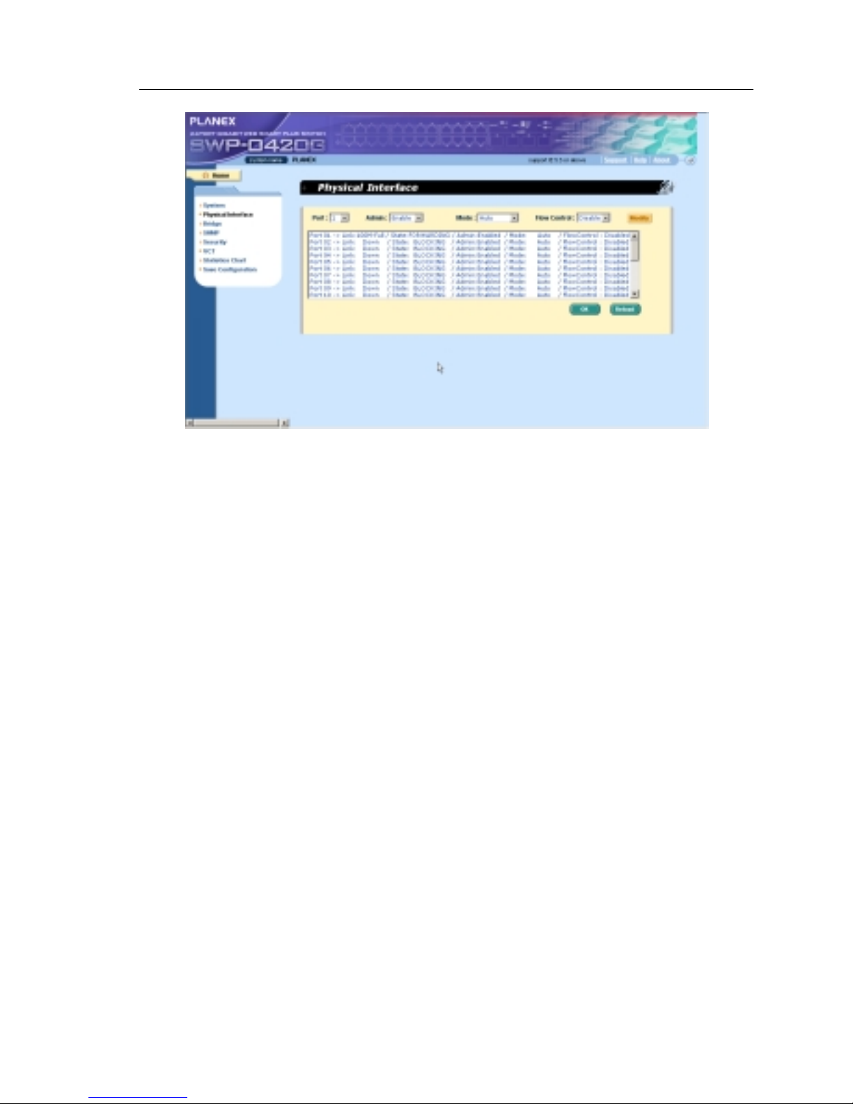
4.4 Physical Interface
The Phy sic al I nter f ace di splays the Eth ernet po rt stat us in real ti me. You can
configure the port in following fields:
Port: select the port to configure
Admin: di sable/ enab le th e po rt
Mode: set the speed and dupl ex mode
Flow Control: ena ble/di sable 802.3 x flow control mechanism
Port Status Window: displays the following information for each port
a) Link status: the link speed and duplex for an existing link,
otherwise link is down
b) State: the STP state (※ Don’t support STP)
c) Admin: the setting value to disable or enable the port
d) Mode: the setting value for link speed and duplex mode
e) Flow Control: the setting value to enable or disable 802.3x flow
control mechanism
Select the cor responding po rt number and configur e the port setting, t hen click
on the
button. The field you change will update the content o f the
display window. H oweve r, t he new settin g s do not t a ke e ffect un til t he “Save
Configurati on” is executed.
SWP-0412/0420G Series L2 Managed Switch User Guide
Figure 16. Physical Interface

SWP-0412/0420G Series L2 Managed Switch User’s Guide
36
4.5 Bridge
The Bridge page group contains most layer 2 configurations, like link
aggregation,...etc..
4.5.1 Link Aggregation
The page configures the link aggregation group (port trunking). The switch
can have 7 link aggregation groups.
Show Trunk: Select “Add a new Trunk” for a new created group . Or select
an existed gr oup t o display on the fol l owing fi elds an d p o rt i co ns.
Port Selection Criterion: the algorithm to distribute packets among the
ports of the link aggregation group according to source MAC address,
destination MAC address, source and destination MAC address, source
IP address, destination IP address, or source and destination IP address.
Name: the g r oup na me.
Trunk ID: a number to identify the trunk group besides the group name.
Remove Trunk: Remove the selected tr unk.
Port Icons: th ese po rt i con s ar e li ste d in a way like the fron t pan el. Y ou
have to click on the i con the select the g roup member s. The port can be
removed from the group by clic king the sele cted por t again.
Click
to make the setting send to the switch (HTTP server). Click
to refresh the settings to current value. To make the configuration
effective, go to “Save Configuration” page, then click
.

SWP-0412/0420G Series L2 Managed Switch User Guide
You have to check the runtime li nk speed and dup lex mode to make sure the
trunk is physically active. Go to Physical Interface and check the link mode in
the runtime status window for the trunk ports. If all the trunk members are in the
same speed and full duplex mode, then the trunk group is set up successfully.
If one of the members is not in the same speed or full duplex mode, the trunk is
not set correctly . Chec k the link partn er and chan ge the setti ngs to have th e
same speed and full duplex mode for all the members of your trunk group.
3 trunk methods are used. It is for per-system, not
per-port
• All the ports in the link aggregation group MUST operate
in full-duplex mode at the same speed.
• All the ports in the link aggregation group MUST be
configured in auto-negotiation mode or full duplex mode.
This configuration will make the full duplex lin k p os sib le. If
you set the ports in full duplex force mode, then the link
partner MUST have the same setting. Otherwise the link
aggregation could operate abnormally.
• All the ports in the link aggregation group MUST have the
same VLAN setting.
• All the ports in the link aggregation group are treated as a
single logical link. That is, if any member changes an
attribute, the others will change too. For example, a trunk
group consists of port 1 and 2. If the VLAN of port 1
changes, the VLAN of port 2 also changes with port 1.

SWP-0412/0420G Series L2 Managed Switch User’s Guide
38
Figure 17. Link aggregation
4.5.2 Mirroring
Mirroring, together with a network traffic analyzer, helps you monitor
network traffics. You can monitor the selected ports for egress or ingress
packets.
Mirror Mode: Enables or disables the mir ror func tion fo r the select ed
group.
Monitor Port: Receives the copies of all the traffics in the selected
mirrored ports.
The monitor port can not belong to any link aggregation group.
The monitor port can not operate as a normal switch port. It does
not switch packets or do address learning.
4 ports are only supported for mirror egress port.

SWP-0412/0420G Series L2 Managed Switch User Guide
Click to make the setting send to the switch (HTTP server). Click
to refresh the settings to current value.
Figure 18. Mirroring page
4.5.3 Traffic Control
Traffic cont rol prev ent s t he swit ch b andw id th fro m fl oo ding pa cke ts in cl udi ng
broadcast packets, multicast packets The limit number is a threshold to limit
the total number of the checked type packets. For example, if broadcast and
multicast a re en abl ed, t he to tal t ra ffi c a mount fo r tho se two ty pe s will not
exceed the limit value. Cli ck
to save the new configuration. To
make the configuration effective, go to “Save Configuration” page , then cli ck
.

SWP-0412/0420G Series L2 Managed Switch User’s Guide
40
Figure 19. Traffic Control
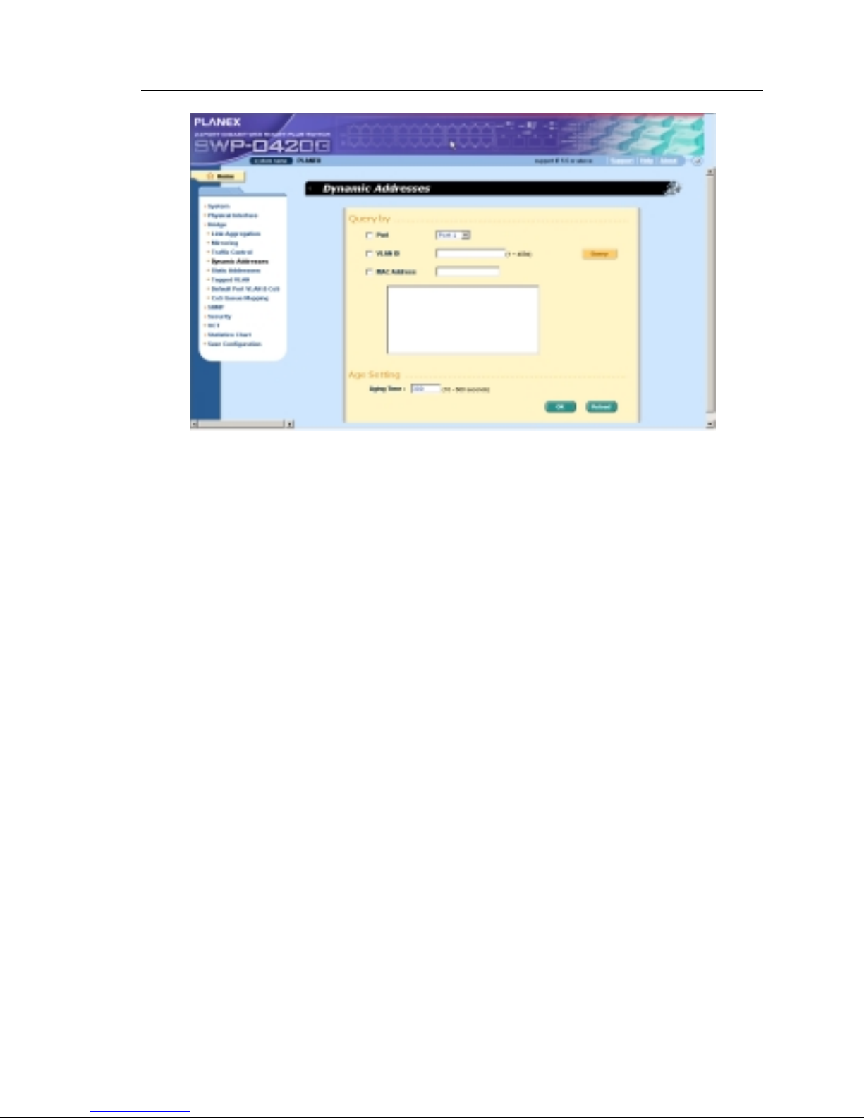
4.5.4 Dynamic Addresses
This page displays the result of dynamic MAC address lookup by port, VLAN
ID, or specified MAC address. The dynamic address is the MAC address
learned by switch, it will age out from the address table if the address is not
learned agai n d u ring t he ag e ti me. U ser can set th e a ge time by e nte ri ng a
valid number from 10 to 600 in seconds. Then cli ck on
to save the
new age value. To make the configu ration e ffective , please go to “Save
Configuration” page, then click on
.
You can look up MAC addresses by checking the port, VLAN ID , or/and MAC
address, then click on the
. The address w indow will display the
result of the query.
SWP-0412/0420G Series L2 Managed Switch User Guide
Figure 20. Dynamic Address
SWP-0412/0420G Series L2 Managed Switch User’s Guide
42
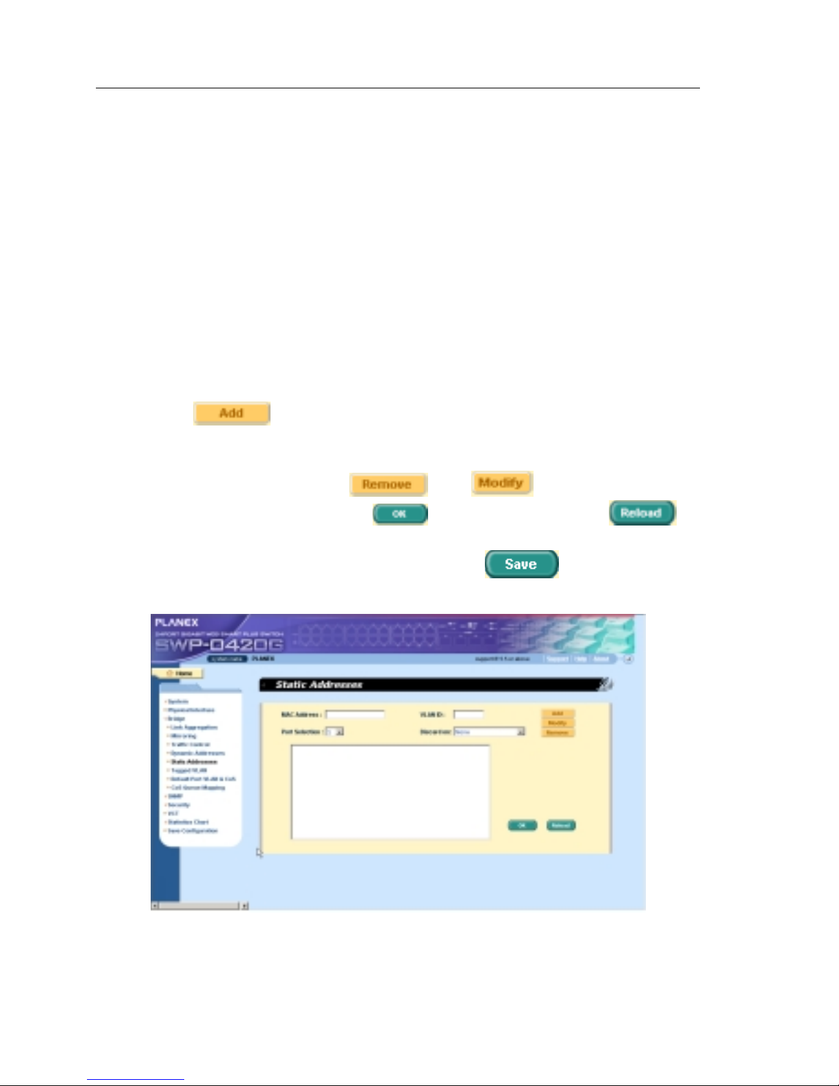
4.5.5 Static Addresses
You can add a MAC address into the switch address table. The MAC address
added by thi s way w ill n ot age ou t fro m t he ad d res s tab le. We call it static
address.
MAC Address: enter the MAC address
VLAN ID: enter th e VLAN ID that the MAC belongs
Port Selection: select the port which the MAC belongs
Discard: you can do packet filtering when the MAC address appea rs in
the packets as destination address, source address, or either of them.
Click on the
when you crea te a new sta ti c MAC ad dre s s by t he
above informati on. Then you will see the new add ed ent ry shows in the
address window. Y ou can remove th e e xi sted a dd ress by sele ctin g the en try
with the mouse, then cli cking on
. The button upda te s th e
existed MAC address entries. Click
to sav e e ff ect i ve. Cl i ck to
refresh the settings to current value. To make the configuration effective,
please go to “save configu ration ” page, then click
.
Figure 21. Static Address

SWP-0412/0420G Series L2 Managed Switch User Guide
4.5.6 Tagged VLAN
You can set up to 256 VLAN groups and show VLAN group in this page. There
is a default VLAN created by the switch . It cannot be modify at all. This feature
prevents the switch from malfunctions. You can remove any existed VLAN
except the default VLAN.
You can assig n the port to be a tagged po rt or an unt agged port by toggling the
port butt on. Ther e a re th ree ty pe s of bu tto n di spl ay s:
“U” type: unta gged po rt t hat will re move VL AN tag s from t he t ran smitte d
packets.
“T” type: Al l p a cket s tran smitt ed fro m this port will be t agged.
“blank” type: This port is not a member of the VLAN group.
If one unta gge d po rt be lon g s to two o r more VLA N groups at t he same t i me, it
will confuse the swit ch and cause flooding traffi cs. To prevent it, the switch only
allow one untagged port belo ngs to one VLAN at the same ti me. That is, the
untagged port belongs to th e VLAN group which is called “PVID” and
configured in the “Default Port VLAN & CoS” page. If you want to assign an
untagged port from one VLAN to ano ther, you have to remov e it from the
original VLAN , o r cha nge it to be tagg ed in th e origin al VLA N fi rst .
Show VLAN: select th e e xi sted V LAN to di splay or select “Add a n ew
VLAN” to create a new VLAN gr oup
Name: the VL AN na me
VLAN ID: this field requires user to enter the VLAN ID when a new VLAN
is created
Remove VLAN: Remove a exis ted VLAN. Thi s field di sappea rs in VLAN
creation page.
Click on
to save the configuration. To make the configuration
effective, go to “Save Configuration” page, then click on
.

SWP-0412/0420G Series L2 Managed Switch User’s Guide
44
Figure 22. Tagged VLAN

SWP-0412/0420G Series L2 Managed Switch User Guide
4.5.7 Default Port VLAN and CoS
Some VLAN tag related field set tings for ea ch port are inclu ded in this pag e. It
includes:
Port: select the port to configure
PVID: port -ba sed VLAN ID. Every un ta gge d p a cket re ceive d fr o m th i s
port will be tag ged w ith t hi s VLAN g roup ID
CoS (Class of Se rvi ce) v alue: ev e ry unt agge d pa cket re ceived from t hi s
port will be a ssign ed to thi s CoS in th e VL AN ta gged. Due t o 4 int e rnal
traffic class mapping to 8 priority, Only CoS value 0,2,5,7 are valid
according to Cos Queue Mapping
Click on
to change the content in the port list window. Cli ck on
to save the configuration. To make the configuration effective, go to
“Save Config uration ” page, then cli ck
.
Figure 23. Default Port VLAN and CoS

SWP-0412/0420G Series L2 Managed Switch User’s Guide
46
4.5.8 CoS Queue Mapping
The switch supports 4 egress queues for each port witch a strict priority
scheduler. That is, ea ch CoS value can map into one of the four queue s. The
queue 4 ha s the hi ghe st p r iori ty to t ransmit t he pa cket s. Cl i ck
to
save the configuration. To make the configuration effective, go to “Save
Configuration” page, then click
Figure 24. CoS Queue Mapping

SWP-0412/0420G Series L2 Managed Switch User Guide
4.6 SNMP
This group offers the SNMP configuration including Community Table, Host
Table , and Trap Set ti n g. To p ro vide more secure m anagement a nd
access contro l.
4.6.1 Community Table
You can type differen t community names and speci fy whether the community
has the privilege to do set action (write access) by checking the box. Click
to save the configuration permanently or to refresh the
page.
Figure 25. Community Table

SWP-0412/0420G Series L2 Managed Switch User’s Guide
48
4.6.2 Host Table
This page links host IP add ress to the communi ty name th at is ente red in
Community Table page. Type an IP address an d select th e communi ty name
from the dr op -dow n li st. Cli ck
to save the configuration
permanently or
to refresh the page .
Figure 26. Host Table

SWP-0412/0420G Series L2 Managed Switch User Guide
4.6.3 Trap Setting
By setting trap destin ation IP addresses and co mmunity names, you can
enable SNMP trap fun ction to se nd trap pa ckets in di fferent ve rsions(v1 or v2 c).
Click
to save the configuration pe rmanently or to
refresh t he pag e.
Figure 27. Trap Setting

SWP-0412/0420G Series L2 Managed Switch User’s Guide
50
4.7 Security
The switch has the 802.1x port-based security feature. Only authorized hosts
are allowed to acc ess the swi tch por t. Tra ffic is bl ocked for host s failed to
authenticate themselves. The authentication service is provided by a RADIUS
server or t he local da ta ba se in the switch.
The VLAN information for the users/ports should be configured in the
authentication server properly before enabling this feature.
4.7.1 Port Access Control
Port Access Control is used to configure various 802.1x parameters. 802.1x
uses either RADIUS server or local database to authenticate port users.
The first pa r t i s t he B ridge (Glo bal ) settin g s:
• Reau th ent i cation : Once e nabl ed , Th e swit ch w ill try to aut hen ti cate t he
port user ag ain w hen th e re-a uth en ti cation t i me i s up.
• Reau th ent i cation Ti me: I f ' Reaut hen ti ca tio n' i s en able d, thi s i s th e ti me
period the switch uses to re-send authentication request to the port
user.(see above)
• Authentication Method: RADIUS or Local database can be used to
authenticate the port user.
• Quiet Period: If authentication failed either from RADIUS or local database,
the switch waits upon thi s time pe riod before sendi ng anothe r
authenti cation req uest to th e por t user.
• Ret ransmi ssion Time: If the po rt user failed to re spond to au thenti cation
request fro m t he switch, t he sw it ch w aits u pon t hi s time period befo re
sending another authenti cation reque st to the po rt user.
• Max Reauthentication Attempts: Retry count if the port user failed to
respond to authen ticatio n requests from the swit ch.
The second part is the port settings. Please click
when you're
done with the modifications.
• Port: Specify which port to configure.

SWP-0412/0420G Series L2 Managed Switch User Guide
• Multi -ho st: If enabl ed, ALL ho sts conne cted to the sele cted po rt are
allowed to u se the po r t i f ONE o f the ho st s pa ssed the aut hen ti catio n. I f
disabled, o nly ONE h o st a mong ot he r ho sts p a ssed t he a uth en ti cation i s
allowed to use the port.
• Auth entication Control: If 'force_authorized ' is selected, the selected por t is
forced autho rized. Thus, tr affic from all hosts is allowed to pass. Otherwi se,
if 'force_unauth oriz ed' is selected , the sele cted port is blocked and no
traffic can go through. If 'Auto' is selected, the behavior of the selected port
is controlled by 802.1x protocol . All ports sh ould be set to 'A uto' unde r
normal conditions.
Click
to make the settings permanent. Click to refresh
the settings to current value.
Figure 28. Port Access Control
4.7.2 Dial-In User
Dial-in User is used to define users in the local database of the switch.
• User Name: New user name.
• Pas swo rd: Pa ssw ord fo r th e n ew u ser .
• Con fi rm Pa sswo rd: En ter th e pa ssword again .

SWP-0412/0420G Series L2 Managed Switch User’s Guide
52
Please click
to add the new user. Click when you're
done with the modifications. Click
when you want to remove the
selected user. Click
to make the settings permanent. Click
to refresh the settings to current value.
Figure 29. Dial-In user
4.7.3 RADIUS
In order to use external RADIUS server, the following parameters are
required to be setup:
• Authentication Server IP: The IP address of the RADIUS server.
• Authentication Server Port: The port number for the RADIUS server is
listening to.
• Authentication Server Key: The key is used for communications between
SWP-0412/0420G and the RADIUS server.
• Con fir m Authenti cation Key: Re-ty pe the key ente red above .

SWP-0412/0420G Series L2 Managed Switch User Guide
The VLAN of the RA DIUS serv er conne cted to the sw itch mu st be
the same as the VLAN of the system management interface.
Please click
to make the settings permanent. Click to
refresh the settings to current value.
Figure 30. RADIUS

SWP-0412/0420G Series L2 Managed Switch User’s Guide
54
4.8 VCT
VCT stands for "Virtual Cable Tester". The major function of VCT is to
detect cable fault(open or short) and report the estimated fault location.
Moreover, VCT can also detect PHY type(100M, 1000M or 10000M) as well
as estimated cable length of normal cable. Cable length estimation only
supports Giga speed mode.
Just select a port number and click
. Test result shall be displayed
accordingly.
Figure 31. VCT

SWP-0412/0420G Series L2 Managed Switch User Guide
4.9 Statistics Chart
The Statistics Chart pa ge s pr ovide ne two r k flow i n d i ffe rent char t s. Y ou can
specify the period time to refresh the chart. You can monitor the network traffic
amount in different graphic chart by these pages. Most MIB-II counters are
displayed in these cha rts.
Click Refresh Rate to set the per iod for retrievi ng new data from the swit ch.
You can differenti ate the statisti cs or ports by selecting Co l or . Fi nally , clic k on
Draw to let the brow ser to d raw the g raphi c cha rt. Ea ch new Dra w will reset
the statistics display.
4.9.1 Traffic Comparison
This page show s the on e stat i sti cs ite m fo r all t he po r t s in o ne g raphi c chart .
Specify the statistics item to display and click the Draw, the browser wi ll show
you the update da ta and refres h the graphi c periodi cally.

SWP-0412/0420G Series L2 Managed Switch User’s Guide
56
Figure 32. Traffic comparison
4.9.2 Error Group
Selecting the Port and di splay Color, th en cl i cki ng the Dra w, th e stati stics
window shows you all the discards or error counts for the specified port. The
data is up dat ed pe riodically.
Figure 33. Error group

SWP-0412/0420G Series L2 Managed Switch User Guide
4.10 Save Configuration
To save configuration permanent ly, y ou have to cli ck . The setting
also takes effective a fte r a successful save.
Sometimes you may want to reset the switch configuration, you can click on
to reset the configuration file to factory default. Of course, a system
reboot will follow this resto ration process.
You will lose all the configurations when you choose to
restore the factory default configurations.
Figure 34. Save Configuration

SWP-0412/0420G Series L2 Managed Switch User’s Guide
58
5 Console Interface
This chapter describes how to use console interface to configure the switch.
The switch provides RS232 connectors to connect your PC. Use a terminal
emulator on your PC such as Hype rTer minal and command line interprete r to
configure th e swit ch. You have to set up th e te rmi nal e mulat o r with b aud rate
9600, 8 bi t da ta , n o pa rity , an d 1 stop bi t, an d n o flow con t rol.
Once you enter CLI mode, typ e “?” will di splay all available comman d help
messages. This is very useful when you are not familiar with the CLI
commands. The CLI mode times out when idle for 10 minutes. You have to
login again t o e nte r C LI mode a fte r t he ti meou t.
All the CLI commands are case sensitive. In order to make them easier to use,
you can enter into different category by typing the full command, then this
category becomes you r working cate gory . Thereafte r, you don ’t have to ty pe
“sys” before any sub-commands. For example, “sys” is a command category
including a lot of sub-commands. You don’t have to type “sys” for the
sub-commands once you change your working category to “sys” by ty p i n g
“sys”. The prompt will become “(system name) sys%” when y our w or king
category is “sys”.

SWP-0412/0420G Series L2 Managed Switch User Guide
5.1 Power On Self Test
POST is executing during the syste m booting ti me. It te sts sy stem memory ,
LED and hardware chips on the swit chboard. It displ ays system informat ion as
the result of system test and initialization. You can ignore the information until
the prompt, “(Planex)%”, appears (see Figure 35).
Figure 35. CLI interface

SWP-0412/0420G Series L2 Managed Switch User’s Guide
60
5.1.1 Boot ROM Command Mode
During the POST process, you can enter a “Boot ROM Command” mode by
pressing <ENTER> key as shown in Figu re 37.
Enter the “?” key to show the help messages for all available commands.
Although the commands are helpful in some situation, we
STRONGLY suggest users not to use them if you don’t
know the command function.
Figure 36. Boot ROM Command Mode

SWP-0412/0420G Series L2 Managed Switch User Guide
5.1.2 Boot ROM Commands
Type “?” in the boot mode to display the valid commands list.
Table 6. Boot ROM commands
Command Parameters Usage Notes
c IP address Configure TFTP client IP
address
g NONE Load and execute firmware
h NONE Display online help
m mask Configure network mask You have to set up the
terminal emulator with
the same baud rate to
make the work
p NONE Display current
configuration
R NONE System reboot
s IP address Configure TFTP server IP
address
t NONE Toggle safe mode
u File name Upload boot
module/firmware via
network using TFTP
protocol
v NONE Display boot rom version
w NONE Toggle administrator
password reset

SWP-0412/0420G Series L2 Managed Switch User’s Guide
62
5.2 Login and Logout
By typing “login” to enter the CL I mode, you have to give a valid user na me
and password. As the firs t time login, you can enter “admin” as the user name
and bypass the password. For security reason, please change the user name
and password a fter log in. Once y ou fo rget th e u se n a me a nd pa sswo rd, y ou
may contact ASUS support team or erase the whole configuration file in the
Boot ROM Command mode. If you take the second choice, the whole syste m
configuration is lost at the same time. That is, you have to configure the switch
again.
You type “logout” to leave the CLI mode safely . This action al lows you to
secure the CLI mode. The next u ser has to d o login again wi th autho rized user
name and password.
5.3 CLI Commands
The switch provides CLI commands for all managed functions. The command
uses are li sted in the categories a s the WEB man agement inte rface. This way,
you can follow the inst ructions and set up the swit ch correct ly as easily as
using WEB interface to configure the switch. “save” command is used to save
the configuration to flash. Some CLI command is only effective after “save”
command is executed.
Always use “?” to get the available commands list and help.
Always use “/” to get back to the root directory.
Type the command only to get help for the command
5.3.1 System Commands
[System Name]
Displays the given na me of the switch. This is an RFC-121 3 defined MIB
object in Syste m Group, and provi des admini strativ e informat ion on the
managed node.
CLI command : sys name <system name de scriptio n>

SWP-0412/0420G Series L2 Managed Switch User Guide
If you put a name in the name description field, the switch system name
changes to the new one.
[System Contact]
Displays the detail information of contact about the switch. This is an
RFC-1213 define d M IB ob ject in Sy ste m Group , and p rovide s cont a ct
information on t he man age d n ode .
CLI command : sys contact <system contact description>
If you put the contac t description in the contact de scription field, the switch
contact will chang e to the new one.
[System Location]
Displays the phy si cal l o cation o f the swit ch. This is an RFC-121 3 de fi ned M IB
object in System Group, and provides the location information on the managed
node.
CLI command : sys locati o n <system location de scripti on>
Type in the lo catio n de s criptio n i n the lo cati on de sc riptio n fie ld to cha nge the
location.
Figure 37. SYS commands

SWP-0412/0420G Series L2 Managed Switch User’s Guide
64
[IP Address/Network Mask]
Displays the static IP address for the switch. This IP address is used for
manageable pu rp ose, i .e. ; netw o r k appli cati on s su ch a s, h tt p serv er, SNM P
server, ftp server , telnet server and SSH server of the switch are all using this
IP address.
CLI command: net interface ip sw0 < IP address> <netmask>
[Default Gateway]
Displays the IP address of the default gateway. This field is necessary if the
switch netwo rk cont ain s on e o r mor e route rs.
CLI command: net route static add <destination subnet/IP> <gateway>
<netmask> <metric>
[Password Protection is] [Enabled/Disabled]
When the password protection is enable d, the web interface will request a us er
name and password authentication while user accesses the switch through the
browser.
CLI command : sys weblogin set <enable/ di sable>
[New/Modify Password]
The default user name is admin. By default, a pa sswo rd is password. You
may set a password by configuring these fields.
CLI command : sys users modify <user name, ‘admin’ by default>
user name (old user name, ‘admin’ by default): <new user name>
password (old passwor d, ‘pas swo rd’ by de fa ult ): <new password>
privilege level(Only 3 is supported): (enter key)
[Reboot]
User can reboot the switch by issuing the reboot command.
CLI command: sys reboot

SWP-0412/0420G Series L2 Managed Switch User Guide
[Upload]
No CLI command for this function. Refer to Boot ROM commands for this
function.
5.3.2 Physical Interface Commands
[Admin] [Enable/Disable]
Displays the port admin status, allow user to turn the port on or off.
CLI command : l2 port admin <port number> < enable/di sable>
[Mode] [Auto/10M-Half/10M-Full/100M-Half/100M-Full/1G-Full]
Displays the cur rent spee d an d d upl e x mode o f the po rt. Th e sp eed an d
duplex mode can be a utomat i cally de te cted w hen au to -ne got iat ion i s ena bled
on a port.
CLI command : l2 port autoneg <port numb er> <e nabl e/di sabl e>
CLI command : l2 port speed <port number> <10/100/100 0>
CLI command : l2 port duplex <port number> <full /half>
[Flow Control] [Enable/Disabl e]
Displays the IEEE 802 .3 x fl ow cont ro l sett ing o f a por t. No te th at t hi s flow
control is op e rating only in full du plex mode.
CLI command : l2 port flow <port numbe r> <ena ble /di sabl e>
[Reload]
Restores the previous port settings from the configuration file.
CLI command : l2 port re tr iev e

SWP-0412/0420G Series L2 Managed Switch User’s Guide
66
5.3.3 Bridge Commands
5.3.3.1 Trunk
[Show Trunk]
Displays a specific trunk group settings. User can create a new trunk group by
specify a unique trunk ID, a trunk name description, the port selection criterion
(rtag) and it s trunk group membe r po rts.
CLI command : l2 trunk show <trunk id>
[rtag]
Set traffic dist ribution algo rithm (1~3 ). The “rtag ” is the packet di stribution
algorith m for the tru nk group .
CLI command : l2 trunk rtag <1|2|3>
Rtag values an d corre spondin g meani ng s:
1: source XOR destinati on MAC( L2),
2: source XOR destinati on IP(L3 )
3. source XOR destination Por t(L4).
[Create Trunk]
Creates a new trun k group by giving trunk ID, rt ag, na me and port nu mbers.
The “rtag” is the packet distr ibuti on algor ithm for th e trun k group.
CLI command : l2 trunk create <trunk id> <trunk name> <port list>
[Add/Remove Trunk]
Trunk group port member s can be added to or removed from an exi sting trunk
group.
CLI command : l2 trunk add <trunk id> <port list>
CLI command : l2 trunk remove <trunk id> <port li st>

SWP-0412/0420G Series L2 Managed Switch User Guide
[Reload]
Restores the previous saved settings of trunking from configuration file.
CLI command : l2 trunk retrieve
5.3.3.2 Mirror
[Create/Remove Mirror Mode]
Displays the mirroring settings of the switch.
CLI command : l2 mirror create <monitor port no> <e nabl e/ di sable>
CLI command : l2 mirror ingress <port list>
CLI command : l2 mirror egress <port list>
CLI command : l2 mirro r remo v e <ingress/egress> <po rt list>
[Reload]
Restores the previous saved settings from configuration file.
CLI command : l2 mirro r re tri ev e
[Show Rate Limiting]
Displays the curren t rate li mita tio n va lue o f the swit ch .
CLI command : l2 rate show
5.3.3.3 RateLimit
[Rate limit Broadcast]
[Rate limit Broadcast and Multicast]
User can limit the traffi c rate for broad cast , multi cast by tur ning the tra ffic
control on.

SWP-0412/0420G Series L2 Managed Switch User’s Guide
68
[Limit Rate]
User can change this value by giving a new limit v alue. This value i s applied to
all of the traffic control mentioned above.It is for the whole system, not per port.
CLI command : l2 rate set <1: bcast/2: bcast and mcast>
<enable/disabl e><li mit rat e>
[Reload]
Restores the previous saved settings from configuration file.
CLI command : l2 rate re tr iev e
5.3.3.4 ARL(Address Resolution Logic)
[Agi n g Ti m e]
User can set t he A RL (Add ress Re solu tion L ogi c) en trie s aging t i me by set ting
the aging ti me v alue .
CLI command : l2 arl age [aging time value ]
[Query by Port]
ARL entries existed in ARL table can be queried according to port number.
CLI command : l2 arl port <port number>
[Query by VLAN ID]
ARL entries existed in ARL table can be queried according to VLAN ID.
CLI command : l2 arl vlan <vlan id>
[Que ry by MAC A ddr e s s ]
ARL entries existed in ARL table can be queried according to MAC address.
CLI command : l2 arl mac <mac address> [vlan id]

SWP-0412/0420G Series L2 Managed Switch User Guide
[MAC Address]
[VLAN ID]
[Port Selection]
[Discard] [none/source/destination/source & destination]
User can add or modify a st atic ARL entry by specify ing a MAC address, VLAN
ID, port number, trunk ID, and discard criteria.
CLI command : l2 arl static <mac> <vlan id> < port n o> <t runk id>
<discard: 0-3>
[Remove]
Static ARL en tries can be deleted by indicating the MAC add ress and its VLAN
ID. These two-field combination is formed as unique entry in ARL table.
CLI command : l2 arl delete <mac address> <vlan id>
[Reload]
Restores the previous saved settings from configuration file.
CLI command : l2 arl retrieve
5.3.3.5 VLAN
[Show VLAN]
Displays the existing VLAN information of the switch.
CLI command : l2 vlan show <vlan id>
[Create VLAN]
Allows user to config the VLAN settings. User may create a new VLAN by
giving a uni que VLA N ID , a VLA N de scriptio n name, and it s po rt member li st,
note that the port member here is indicated as tagged port member. To specify
a VLAN port member as untagged port, CLI command utportadd can achieve
this purpose. User may use CLI command add or remove to further add some
port members to a VLAN or exclude some existing port members from a
VLAN.

SWP-0412/0420G Series L2 Managed Switch User’s Guide
70
CLI command : l2 vlan create <vlan id> <vlan n a me> <por t l i st>
[add/remove port from VLAN]
CLI command : l2 vlan add <vlan id> <port list>
CLI command : l2 vlan remove <vlan id> <port list>
[set untag-port ]
CLI command : l2 vlan utportadd < vlan i d> <u nt agg ed por t l i st>
[Delete VLAN]
Allows user to completely destroy an existing VLAN.
CLI command : l2 vlan delete <vlan id>
[Reload]
Restores the previous saved settings from configuration file.
CLI command : l2 vlan retrieve
5.3.3.6 Port
[Show Port]
Displays the port configuration
CLI command : l2 port show <port id or * for all ports>
[PVID]
Sets the default VLAN for a port by giving a VLAN ID and its associated port
memb er list.
CLI command : l2 port vlan <vlan id, 4095 to disable the port-based
vlan> <port list>

SWP-0412/0420G Series L2 Managed Switch User Guide
[CoS Value]
Sets the Class of Service for a port by assigning it a priority (with range
of 0-7) criteria value for untagged packets. .Due to 4 internal traffic
class mapping to 8 priority, Only 4 Cos value (ex. 0,2,5,7 for default
queue mapping) are valid according to Cos Queue Mapping.
CLI command : l2 port priority <CoS> <port list >
[Reload]
Restores the previous saved settings from configuration file.
CLI command : l2 port retrieve
5.3.3.7 QoS
[Cos] [Map]
Allows user to map the CoS pri ority (with range of 0-7) for a bu ffer queue (tota l
of 4, with queue ID of 1-4).
CLI command : l2 cos map <queue id (1-4)> <cos (0-7)>
[Cos] [Sched]
Allows user t o set sched uling with stri ct p riori ty ba sed o r w eight p riori ty ba sed.
CLI command : l2 cos sched <mode (1: strict 2: weighted round
robin)> <Q1 weig ht> <Q2 weig ht > <Q 3 we igh t> <Q 4 weig ht>
[Reload]
Restores the previous saved settings from configuration file.
CLI command : l2 cos retrieve

SWP-0412/0420G Series L2 Managed Switch User’s Guide
72
5.3.4 SNMP
5.3.4.1 Community
[Add / Set / Delete Community Name]
A community entry contains a community description string and a set of
privileges. Get privilege are turned on by default, and user can specify whether
to give it the Set P rivil ege whil e creat e a new en t ry.
[Add]
CLI command : snmp co mmu n i ty add
New community string: <new community string>
Get privileges: [y, a lw ay s tu rn on by de fau l t ]
Set privileges? (y/n ):[n] < set privilege, y for ‘yes’; n for ‘no’>
[Set]
CLI command : snmp co mmu n i ty set
User can modify a community entry in the table by reassigning its community
string and pr ivilege s.
Community entry (table index): <entry id to config>
Community string (old community string): <new community string>
This action will modify all hosts with community string from 'old community'
to 'new community'.
Are you sure? (y/n ):[y ] <y for ‘y es’; n for ‘no’>
Get privileges: [y, a lw ay s tu rn on by de fau l t ]
Set privileges? (y/n ):[n] <set priv ilege, y for ‘yes’; n for ‘no’>
[Delete]

SWP-0412/0420G Series L2 Managed Switch User Guide
CLI command : snmp community delete
Allows user to delete a community entry from community table.
Community entry (table index): <entry id to delete>
This action will delete all hosts in community string with 'delete community'.
Are you sure? (y/n ):[y ] <y for ‘y es’; n for ‘no’>
[Reload]
Restores the previous saved settings from configuration file.
CLI command : snmp co mmu n i ty retr ie ve
5.3.4.2 SNMP Host
[Add SNMP host]
A host entry contain s a host IP addre ss, networ k mask and its dedi cated
community string.
CLI command : snmp host add
Host IP/Subnet: <IP address>
Netmask: <ne tma sk>
Community: <communit y str in g>
[Set SNMP host]
CLI command : snmp host set
User can modify a host entry in the table by reassigning its al lowed IP addre ss,
network mask and community string.
Host table entry (table index): <en t ry id to config>
Host IP/S u bne t (ol d IP address) : <new IP addre ss>
Netma sk (ol d ne tmas k ): <new netmask>
Community (old community string): <new community string>

SWP-0412/0420G Series L2 Managed Switch User’s Guide
74
[Delete SNMP host]
CLI command : snmp host delete
Allows user to delete a host entry from host table.
Entry id (table index): <entry id to delete>
[Reload]
Restores the previous saved settings from configuration file.
CLI command : snmp host retrieve
5.3.4.3 Trap
[Add/Set/Delete trap]
A trap entry contains SNMP version (currently support version 1 and
version 2c), a destination IP address and the remote community string.
[Add]
CLI command : snmp trap add
SNMP version? (1 /2 c):[ 1, by de fault ] < snmp version>
Destination IP: <IP address>
Community: <community string>
[Set]
CLI command : snmp trap set
User can modi fy a t rap en t ry in t he ta ble by reas signin g i t s SNMP ve r sion,
destination IP address and community string.
Trap table entry (table index): <entry id to config>
SNMP version? (1 /2c ):[ old snmp v e r sion] < new sn mp v ers ion>
Destination IP (old IP address): <new IP address>

SWP-0412/0420G Series L2 Managed Switch User Guide
Community (old community string): <new community string>
[Delete]
CLI command : snmp trap delete
Allows user t o d ele te a t rap e nt ry from t rap ta ble .
Trap table entry (table index ): <entry id to delete>
[Reload]
Restores the previous saved settings from configuration file.
CLI command : snmp trap retrieve

SWP-0412/0420G Series L2 Managed Switch User’s Guide
76
5.3.5 Security Commands
5.3.5.1 dot 1x
[Reauthentication]
Allows user to e nab le o r d i sable pe rio di c r eau the nti cati on.
CLI command : security dot1x bridge reauth <enable / disable>
[Reauthentication Time]
Allows user t o set up th e reau the ntication time.
CLI command : security dot1x b ri dge reauth time <reauthenti c ati on tim e
(1-4294967295 sec)>
[Authentication Method]
Allows user to set up the authent ication method ( RADIUS or Lo cal databa se).
CLI command : security dot1x b ri dge au th met h < type (1:local 2: radius)>
[Quiet Period]
Allows user to set up the quiet pe riod.
CLI command : security dot1x bridge quie tperi od <quiet period (1-65535
sec)>
[Retransmission Time]
Allows user to set up the retran smissio n time.
CLI command : security dot1x b ri dge retxtime <retransmission time
(1-65535 sec)>
[Max Reauthentication Attempts]
Allows user to set up the max nu mber of the r eauthe nticat ion atte mps.

SWP-0412/0420G Series L2 Managed Switch User Guide
CLI command : security dot1x bridge reauthmax <max reauthentication
attem ps (1-1 0)>
[Multi-host]
Allows user to enable or disable Multi-host on some specific ports.
CLI command : security dot1x po r t mul tiho st < ena ble /di sable><po rt
list/*>
[Authentication Control]
Allows user to set up the authentication control of some specific ports.
CLI command : security dot1x po rt au th ctrl <type (1: force_authorized
2:force_unauth o riz ed 3 : aut o)><p or t li st/*>
[Reload]
Restores the previous saved settings from configuration file.
CLI command : security dot1x retrieve
5.3.5.2 Dialuser
[Create/Modi fy/Rem ove Dial user]
Create users in th e local data base of the switch for 802.1x au thenti cation. A
user entry contains a user name, password and dynamic VLAN.
CLI command : security dialinuser create
User Name: <user name string>
Password: <password string>
Confirm Password: <confirm password string>
CLI command : security dialinuser remove <user name/*>
Allows user to delete a user entry from the local database.
CLI command : security dialinuser modify <user name/*>

SWP-0412/0420G Series L2 Managed Switch User’s Guide
78
Allows user to modify a user entry from the local database. It contains a user
name, password.
User Name: <new user name string>
Password: <new pa ssw ord st ring>
Confirm Password: <new confi rm password st ring>
[Reload]
Restores the previous saved settings from configuration file.
CLI command : security dialinuser retrieve
5.3.5.3 Radius
[Set RA DIUS U ser ]
Allows user to config the RADIUS server IP, server port and server key .
CLI command : security radiu s se t
authentication server ip <ip/none>: (ol d serve r i p)<new se rver ip >
authentication server port <port/default>: (old server port)<new
server port>
authentication server key <key/none>: <server key>
confirm authentication key <key/none>: <confirm server key>
[Reload]
Restores the previous saved settings from configuration file.
CLI command : security ra diu s ret rie ve

SWP-0412/0420G Series L2 Managed Switch User Guide
5.4 Miscellaneous Commands
sys uptime: show the time since the system boot up.
sys date: show the current date and time
sys settime: set the current time
net ping: ping remote host
net route show: display the entries in the routing table

SWP-0412/0420G Series L2 Managed Switch User’s Guide
80
6 IP Addresses, Network Masks, and
Subnets
6.1 IP Addresses
This section pert ains on ly to IP addresse s for IPv4 (v ersion 4 of
the Internet Protocol). IPv6 addresses are not covered.
This section a ssume s bas ic kn ow ledge of bin ary num bers, b its,
and bytes. For details on this subject, see Appendix 6.
IP addresses, the Intern et's ver sion o f tele phone number s, are u sed to iden tify
individual node s (co mpute rs or dev i ces ) on th e Int e rnet. Eve ry IP ad d ress
contains four numbers, each from 0 to 255 and separated by dots (periods),
e.g. 20.56.0.211. These numbers are called, from left to right, field1, field2,
field3, and field4.
This style of writing IP addresses as decimal numbers separated by dots is
called dotted decimal notation. The IP address 20.56.0.211 is read "twenty dot
fifty- six dot z ero d o t tw o -el eve n."
6.1.1 Structure of an IP address
IP addresses have a hierarchical de sign similar to tha t of telepho ne number s.
For example, a 7-digit telephone number starts with a 3-digit prefix that
identifie s a group of thousands of telephone lines, and ends with fou r digits that
identify on e spe ci fi c line in tha t g roup.
Similarly, IP addresse s contain two ki nds of info rmation.
Network ID
Identifies a particular network within the Internet or intranet
Host ID
Identifies a particular computer or device on the network

SWP-0412/0420G Series L2 Managed Switch User Guide
The first part of eve ry IP addre ss contai ns the netw ork ID, and th e rest o f the
address contain s the host ID. The length o f the networ k ID depend s on the
network's class (see following section). Table 7 shows the structure of an IP
address.
Table 7. IP address structure
Field1 Field2 Field3 Field4
Class A Network ID Host ID
Class B Network ID Host ID
Class C Network ID Host ID
Following are examples of valid IP addresses:
Class A: 10 .30 .6 .12 5 (n etw ork = 10, host = 30.6 .12 5 )
Class B: 129.88.1 6.49 (ne twor k = 129.88, ho st = 16.49)
Class C: 1 92. 60 .20 1.1 1 (netw o rk = 19 2. 60. 201 , ho st = 11 )

SWP-0412/0420G Series L2 Managed Switch User’s Guide
82
6.1.2 Network classes
The three commonly used network classes are A, B, and C. (There is also a
class D but it has a special use beyond the scope of this discussion.) These
classes have different uses and characteristics.
Class A networks are the Internet's largest networks, each with room for over
16 million hosts. Up to 126 of th ese huge netwo rks can exist, for a total of over
2 billion hosts. Because of their huge size, these networks are used for WANs
and by organizations at the infrastructure level of the Internet, e.g. your ISP.
Class B networks are small er but still quite large, each being able to hold over
65,000 hosts. There can be up to 16,384 class B networks in existence. A
class B network might be appropriate for a large organization such as a
business or government agency.
Class C networ ks are the smal lest, only able to hold 2 54 hosts at most, but the
total possible number o f class C networks exceed s 2 million (2,0 97,152 to be
exact). LANs connected to the Internet are usually class C networks.
Some important notes regarding IP addresses:
The class can be determined easily from field1:
field1 = 1-126: Class A
field1 = 12 8 -191: Class B
field1 = 19 2 -223: Class C
(field1 values not show n are reserved for special uses)
A host ID can have any value except all fields set to 0 or all field s set to 255, as
those values are reserved for special uses.

SWP-0412/0420G Series L2 Managed Switch User Guide
6.2 Subnet masks
A mask looks like a regular IP address, but contains a
pattern of bits that tel ls w hat parts o f an IP addr ess are the
network ID and what parts are the host ID: bits set to 1
mean "this bit is part of the network ID" and bits set to 0
mean "this bit is part of the host ID."
Subnet masks are used to de fine subne t s (what you get after dividing a
network into smaller pieces). A subnet's network ID is created by "borrowing"
one or more bits from the host ID portion of the address. The subnet mask
identifie s these host ID bit s.
For example, consider a class C network 192.168.1. To split this into two
subnets, you w oul d u se the su bne t mask:
255.255.255. 128
It's easie r t o see w ha t 's h appe ning if we write thi s in bi na ry :
11111111. 11 1111 11 . 1 1111 111 .10 000 000
As with any class C address, all of the bits in field1 through field 3 are part of
the network ID, but no te how the mask specifies that the first bit in field 4 is also
included. Since this extra bit has only two values (0 and 1), this means there
are two subne ts. Each subnet uses the re maining 7 bits in field 4 for its ho st IDs,
which range from 0 to 127 (instead of the usual 0 to 255 for a class C address).
Similarly, to split a class C netw ork into four subn ets, the mask is:
255.255.255. 192 or 1111111 1. 11 111 111 . 1 111 1111 .11 000 000

SWP-0412/0420G Series L2 Managed Switch User’s Guide
84
The two extra bits in Field 4 can have four values (00, 01, 10, 11), so there are
four subnets. Ea ch subnet uses the r emainin g six bits in fie ld4 fo r its host ID s,
ranging from 0 to 63.
Sometimes a subne t mask d oes not s pecify any a dditional
network ID bits, and thus no subnets. Such a mask is
called a default subnet mask. These masks are:
Class A: 255.0.0.0
Class B: 255.255.0.0
Class C: 255.255.255.0
These are called default because they are used when a
network is initially configured, at which time it has no
subnets.

SWP-0412/0420G Series L2 Managed Switch User Guide
7 Troubleshooting
This section gives instructions for using several IP utilities to diagnose
problems. A list of possible problems with suggestion actions is also
provided.
All the known bugs are listed in the release note. Read the release note
before you set up the switch. Contact Customer Support if these
suggestions do not resolve the problem.
7.1 Diagnosing problems using IP utilities
7.1.1 ping
Ping is a command you can use to chec k whether you r PC can recognize
other computers on your network and the Internet. A ping command sends a
message to the computer you specify. If the computer receives the message, it
sends messages in reply. To use it, you must know the IP add ress of the
computer with whi ch you a re trying to communi cate.
On Windows-based computers, you can execute a ping command from the
Start menu. Cli ck the Sta rt button, and then cli ck Run. In the Open te xt box,
type a statement such as the following:
ping 192.168.1.1
Click
. You can substitute any private IP address on your LAN or a
public IP ad d ress for an I nt e rnet site, i f known .
If the target computer receives the message, a Command Prompt window
appears as shown in Figu re 5 2.

SWP-0412/0420G Series L2 Managed Switch User’s Guide
86
Figure 38. Using the ping utility
If the target comput er canno t be locate d, you will receive the message
“Request timed out.”
Using the pin g co mmand, you can test whet he r th e p ath to t he swi t ch is
working (using the pre- configured de faul t LAN IP addre ss 192.168 .1.1 ) or
another addr e ss you a ssigne d.
You can al so te st wheth e r a cce ss to the I nte rne t i s w orki ng by ty ping an
external addr ess, such as that for www.y ahoo.co m (216.1 15.108.2 43). If you
do not know th e IP add ress o f a p a rticula r In te rn et lo cation, you can u se t he
nslookup command, as explained in the following section.
From most other IP-enabled operating systems, you can execute the same
command at a command prompt or through a system administration utility.

SWP-0412/0420G Series L2 Managed Switch User Guide
7.1.2 nslookup
You can use the nslookup command to determine the IP address associated
with an Internet site name. You specify the common name, and the nslookup
command looks up the name on your DNS server (usually located with your
ISP). If that name i s not an ent ry in your ISP’s DNS tabl e, the reque st i s then
referred to ano ther highe r-l evel serv er, and so on, until the entry i s found. The
server then returns the a ssociated IP add ress.
On Windows-based computers, you can execute the nslookup command from
the Start menu. Click the Start button, then click Run. In the Open text box,
type the foll ow ing:
nslookup
Click
. A Command Prompt window displays with a bracket prompt
(>). At the p rompt , ty pe the na me of the Inte rnet addre ss you a re inte rested in,
such as www.absnews.com.
The window display s the associ ate IP add ress, if known . See Figure 39.
Figure 39. Using the nslookup utility
There may be seve ral add resse s as sociat ed with an I nte rnet na me. Thi s i s
common for web site s that receive heavy traffi c; they use multiple, re dundan t
servers to carry the same information.
To exit from the nslookup utility, type exit and press <Enter> at the command
prompt.

SWP-0412/0420G Series L2 Managed Switch User’s Guide
88
7.2 Simple fixes
The following table lists some common problems that you may encounter
when installing or using the switch, and the suggested actions to solve the
problems.
Table 8. Troubleshooting
Problem Suggested Action
LEDs
SYSTEM LED does
not light up after the
switch is turned on.
Verify if the power cord is securely connected to the switch and a
wall socket/power strip.
Fast Ethernet Link
LED does not
illuminate after an
Ethernet cable is
attached.
1. Verify if the Ethernet cable is securely connected to your LAN
switch/hub/PC and to the switch. Make sure the PC and/or
hub/switch is turned on.
2. Verify if your cable is sufficient for your network requirements. A
100 Mbps network (100BaseTx) should use cables labeled Cat
5. 10Mbit/sec cables may tolerate lower quality cables.
Network Access
PC cannot access
another host in the
same network
1. Check the Ethernet cabling is good and the LED is green.
2. If the port LED is amber, check if this port is disabled.
PCs cannot display
web configuration
pages.
1. The switch is powered up and the connecting port is enabled.
The factory default IP for the switch is 192.168.1.1.
2. Verify your network setup in your PC for this information. If your
PC does not have a valid route to access the switch, change the
switch IP to an appropriate IP that your PC can access.
3. Ping “switch IP” from the PC, if it still fails, repeat step 2.
4. If ping is successful but the web configuration still fails,
connecting PC through the console port by a RS232 , check if
any filter rule or static MAC address is set to block th e WEB
traffics.
Web Configuration Interface
You forgot/lost your
WEB Configuration
Interface user ID or
password.
1. If you have not changed the password from the default, try using
“admin” as the user ID and bypassing password.
2. Login to console mode through RS232 , use “sys user show” to
display the lost information

SWP-0412/0420G Series L2 Managed Switch User Guide
Problem Suggested Action
Some pages do not
display complete ly
1. Verify that you are using Internet Explorer v5.5 or later.
Netscape is not supported. Support for Javascript® must be
enabled in your browser. Support for Java® may also be
required.
2. Ping the switch IP address to see if the link is stable. If some
ping packets fail, check your network setup to make sure a valid
setting.
Changes to
Configuration are
not being retained.
Be sure to click on
button in the Save Configuration
page to save any changes.
Console Interface
Cannot show the
texts on the terminal
emulator.
1. The factory default baud rate is 9600, no flow control, 8 bit data,
no parity check and stop bit is one.
2. Check if the cable is good.
 Loading...