

Page 1

- 1 -
Page 2

- 2 -
FMX-24NZ Layer2 Intelligent Switch Manager User Menu
1. INTRODUCTION ............................................................................................................................................................5
1.2 INSTALLATION ............................................................................................................................................................. 6
1.3 INITIAL SET UP FOR MANAGEMENT .............................................................................................................................8
1.3.1 out-of-band Terminal-mode Management ............................................................................................................8
1.3.2 In-band management through Ethernet................................................................................................................9
1.3.3 Telnet management ............................................................................................................................................. 11
1.4 LED INDICATORS INFORMATION .............................................................................................................................. 12
2. WEB MANAGEMENT FUNCTION............................................................................................................................ 13
2.1. WEB MANAGEMENT HOME OVERVIEW ..................................................................................................................13
2.2. PORT STATUS............................................................................................................................................................. 14
2.2.1 single port counter and status.......................................................................................................................15
2.3. PORT STATI STI CS ...................................................................................................................................................... 16
2.4. SHOW MAC TABLE .................................................................................................................................................. 18
2.5. ADMINISTRATOR....................................................................................................................................................... 19
2.5.1. IP Address/Subnet Mask/Gateway..................................................................................................................... 19
2.5.2 Switch Setting .....................................................................................................................................................20
2.5.2.1 Advanced .......................................................................................................................................................................20
2.5.2.2 Misc Config ...................................................................................................................................................................22
2.5.3 Console Port Information...................................................................................................................................23
2.5.4 Port Controls...................................................................................................................................................... 23
2.5.5 Trunking ............................................................................................................................................................. 26
2.5.5.1 Aggregator setting.......................................................................................................................................................... 26
2.5.5.2 Aggregator Information..................................................................................................................................................27
2.5.5.3 State Activity..................................................................................................................................................................28
2.5.6 IGMP and MAC Filter .......................................................................................................................................29
2.5.6.1. IGMP Snooping ............................................................................................................................................................29
2.5.6.2. Static MAC Address...................................................................................................................................................... 30
2.5.6.3 MAC filtering.................................................................................................................................................................31
2.5.7. VLAN configuration ..........................................................................................................................................32
2.5.7.1. Port Based VLAN.........................................................................................................................................................34
2.5.7.2. 802.1Q VLAN...............................................................................................................................................................35
2.5.8. Spanning Tree....................................................................................................................................................39
2.5.9. Port Mirror........................................................................................................................................................41
2.5.10. SNMP/Trap Manager ......................................................................................................................................42
2.5.11 Security Manager ............................................................................................................................................. 44
Page 3

- 3 -
2.5.12 802.1x Configuration.....................................................................................................................................45
2.5.13 Ping .................................................................................................................................................................. 47
2.6. TFTP UPDATE FIRMWARE ....................................................................................................................................... 48
2.7. CONFIGURATION BACKUP........................................................................................................................................ 49
2.7.1. TFTP Restore Configuration .............................................................................................................................49
2.7.2. TFTP Backup Configuration .............................................................................................................................49
2.8. RESET SYSTEM .........................................................................................................................................................50
2.9. REBOOT .................................................................................................................................................................... 50
3. CONSOLE -- 1K XMODEM UPDATE FIRMWARE................................................................................................. 51
4. OUT-OF-BAND TERMINAL MODE MANAGEMENT............................................................................................ 54
4.1 MAIN MENU............................................................................................................................................................... 55
4.2 SWITCH STATI C CONFIGURATION .............................................................................................................................55
4.2.1. Port Configuration ............................................................................................................................................57
4.2.2. Trunk Configuration .......................................................................................................................................... 59
4.2.3. VLAN Configuration..........................................................................................................................................60
4.2.3.1. VLAN Configure ..........................................................................................................................................................60
4.2.3.2. Create a VLAN Group..................................................................................................................................................62
4.2.3.3. Edit / Delete a VLAN Group.........................................................................................................................................64
4.2.3.4. Groups Sorted Mode .....................................................................................................................................................65
4.2.4. Misc Configuration ...........................................................................................................................................66
4.2.4.1. Ping...............................................................................................................................................................................67
4.2.4.2. MAC Age Interval......................................................................................................................................................... 67
4.2.4.3. Broadcast Storm Filtering .............................................................................................................................................68
4.2.4.4. Max bridge transmit delay bound..................................................................................................................................69
4.2.4.5. Port Security .................................................................................................................................................................69
4.2.4.5. Collisions Retry Forever...............................................................................................................................................70
4.2.4.6. Hash Algorithm............................................................................................................................................................. 71
4.2.4.7. IFG Compensation........................................................................................................................................................71
4.2.5. Administration Configuration ...........................................................................................................................73
4.2.5.1. Change Username .........................................................................................................................................................73
4.2.5.2. Change Password..........................................................................................................................................................74
4.2.5.3. Device Information .......................................................................................................................................................74
4.2.5.4. IP Configuration............................................................................................................................................................75
4.2.6. Port Mirror Configuration ................................................................................................................................76
4.2.7. Priority Configuration.......................................................................................................................................77
4.2.7.1. Port Static Priority.........................................................................................................................................................77
4.2.7.2. 802.1p Priority Configuration .......................................................................................................................................78
4.2.8. MAC Address Configuration .............................................................................................................................79
Page 4

- 4 -
4.2.8.1. Static MAC Address...................................................................................................................................................... 79
4.2.8.2. Filtering MAC Address .................................................................................................................................................83
4.3. PROTOCOL RELATED CONFIGURATION................................................................................................................... 87
4.3.1. STP....................................................................................................................................................................87
4.3.1.1. STP Enable....................................................................................................................................................................88
4.3.1.2. STP System Configuration ............................................................................................................................................88
4.3.1.3. Purport Configuration ...................................................................................................................................................90
4.3.2. SNMP ................................................................................................................................................................ 91
4.3.2.1. System Options.............................................................................................................................................................91
4.3.2.2. Community Strings .......................................................................................................................................................93
4.3.2.3. Trap Managers ..............................................................................................................................................................96
4.3.3. GVRP.................................................................................................................................................................98
4.3.4. IGMP.............................................................................................................................................................. 99
4.3.5. LACP (Link Aggregation Control Protocol) .................................................................................................100
4.3.5.1. Working Port Setting................................................................................................................................................100
4.3.5.2. State Activity............................................................................................................................................................101
4.3.5.3. LACP Status .............................................................................................................................................................102
4.3.6. 802.1x Protocol ............................................................................................................................................ 104
4.3.6.1. 802.1x Enable ..........................................................................................................................................................104
4.3.6.2. 802.1x System Configuration...................................................................................................................................106
4.3.6.3. 802.1x PerPort Configuration ..................................................................................................................................107
4.3.6.4. 802.1x Misc Configuration ......................................................................................................................................108
4.4. STATUS AND COUNTERS ..........................................................................................................................................109
4.4.1. Port Status.................................................................................................................................................... 109
4.4.2. Port Counters............................................................................................................................................... 110
4.4.3. System Information........................................................................................................................................111
4.5. REBOOT SWITCH..................................................................................................................................................112
4.5.1. Default............................................................................................................................................................. 112
4.5.2. Restart ............................................................................................................................................................. 112
4.6. TFTP UPDATE FIRMWARE ..................................................................................................................................... 113
4.6.1. TFTP Update Firmware .................................................................................................................................. 113
4.6.2. Restore Configure File .................................................................................................................................... 114
4.6.3. Backup Configure File .................................................................................................................................... 115
5. APPLICATION EXAMPLES................................................................................................................................ 116
5.1. LAN APPLICATION USED WITH SWITCH ......................................................................................................... 116
5.2. TRUNKING APPLICATION USED WITH SWITCH ............................................................................................... 118
Page 5

- 5 -
1. Introduction
FMX-24NZ switch is a high performance web-managed SNMP Layer 2 switch that provides users
with 24 10/100Mbps Ethernet and 2 1000Mbps Gigabit ports (optional). This Switch has SNMP
management and remote control capabilities such as “Web Cluster”. The Gigabit module, which can
be copper or fiber media, supports 1000BASE-SX, 1000BASE-LX or 1000BASE-T, allowing users
to increase their network response time at gigabit speeds and with great flexibility. A RS-232 serial
port provides an easy way for installation and initial set-up.
Non-blocking and maximum wire speed performances are designed on all ports. The Switch not only
supports Auto-Negotiation, but also Auto-MDIX function on all switched 24 10/100M RJ-45 ports
and two Gigabit Copper ports in both half or full duplex mode. The Auto-MDIX function makes it
convenient for the user, because it eliminates cabling on straight-line or cross-line issues.
FMX-24NZ switch provides a convenient way to operate layer 2 management through the browser.
The User-friendly drop-down menu allows the user to easily learn, control and monitor. It supports
not only traditional SNMP function, but also RMON 1,2,3,9 groups for advanced network analysis. A
new management tool called “Single IP” is implemented here to provide the administrator an access
right to enter private IP domain through a single real IP. By this management tool, network manager
can remotely control his far-side servers in private IP domain without being there.
The Switch also supports both port-based VLAN and Tag-based. To increase bandwidth application,
it supports 7 groups with up to 4 ports Trunk, and moreover, these trunk ports provide fair-over
function to provide back up when one or more ports malfunction.
Totally front access design and full LED status display ease user’s installation and inspection and
maintenance efforts at rack mount environments. The extra LED display reflecting the fan status
allows for quick diagnosis of over-heat issues.
Page 6

- 6 -
1.1 Unpacking
Open the shipping carton of the Switch and carefully unpack its contents, the carton should contain
the following items:
z One FMX-24NZ, 24 port Fast Ethernet Layer 2 Switch.
z Mounting Kit: 2 mounting brackets and screws
z Four rubber feet with adhesive backing.
z One AC power cord.
z One RS-232 cable
z This User’s Guide (CD-ROM).
1.2 Installation
You can use the following guidelines when choosing a place to install the Switch.
z The surface must support at 3 kg. Do not place heavy object on the Switch.
z Visually inspect the power cord and AC power connector.
z Make sure that there is proper heat dissipation form and adequate ventilation around the Switch.
Desktop or Shelf Installation:
When installing the Switch on the desktop of shelf, the rubber feet included with the device should
first be attached. Attach these cushioning feet on the bottom at each corner of the device. Allow
adequate space for ventilation between the device and the objects around it.
Rack Installation:
The FMX-24NZ switch can be mounted in an ELA standard-sized, 19-inch rack, which can be placed
in a wiring closet with other equipment. To install, attach the mounting brackets on the switch side
panels (one on each side) and secure them with the screws provided. Then, use the screws provided
with the equipment rack to mount the switch on the rack.
Page 7

- 7 -
Power on:
The FMX-24NZ switch can be used with an AC power supply 90-260V AC, 50-60Hz. The AC power
connector is located at the rear of the unit. The switch’s power supply will adjust to the local power
source automatically and may be turned on without having any or all LAN segment cables connected.
After the power switch is turned on, the LED indicators should respond as fallows:
z All LED indicators will momentarily blink. This blinking of the LED indicators represents a
reset of the system.
z The power LED indicator will blink while the Switch loads onboard software and performs a
self-test. After approximately 20 seconds, the LED will light again to indicate the switch is in a
ready state.
z The Speed, Link/Activity LED indicator may remain ON or OFF depending on every port’s
situation.
z The fan LED will be vanished if fan works normally, or LED goes RED if fan stop
or failed.
Page 8

- 8 -
1.3 Initial set up for management
There are two management ways can be chosen, one is out-of-band management, you work this way
with a PC and connect your PC and switch through RS232 cable. The other way is
in-band-management, you also work with a PC but connect your PC and switch through Ethernet
network no matter local or remotely, or simply directly connect your PC and switch through an
Ethernet cable. Before you activate the management function with the Switch, you have to read the
instructions below carefully and do some proper setting to insure you can access the switch through
your PC, then the switch devices will be replied or responded correctly as you wish.
1.3.1 out-of-band Terminal-mode Management
First, turn on your PC and execute with terminal mode program, such as, if you are in Microsoft
Window environment, you may choose “super terminal “from programs that are listed for
communication. Then follow the steps below:
Step 1: Set Hyper Terminal parameters on your PC
Bits Rate per second = 9600
Parity = None
Data Bits = 8
Stop Bit = 1
Flow Control = None
Step 2:
After setting the above on the PC, then connect your switch device with RS-232 cable, then type the
“enter” key, then, the device will response the Main Menu to you and ask you to input the username
and password. The default username is “admin” and the password is “0000” for default. To know
more about operation in this mode, please refer the instructions in chapter 4 of this manual to perform
all function you want.
Page 9

- 9 -
1.3.2 In-band management through Ethernet
In addition to terminal mode operation, FMX-24NZ switch also supports in-band management
through browser, this function is much more user-friendly than terminal mode, because it can be
operated through mouse on the PC screen and moreover it can be performed either locally or remotely
through Ethernet.
Before you can access the switch, you have to know following things.
First you have to know the IP Address and Subnet Mask of both your switch and your PC. The
default value of the IP Address and Subnet Mask within the switch can be got through terminal
mode operation described in chapter 4, while the IP Address and Subnet Mask of PC can be found
in your PC system.
Second, in general, within a network, the members in the same network domain must have the same
Subnet IP unless there are routers between them, or, members in the same network domain can’t talk
to each others, so make sure the communication members in the same domain must have
different IP Addresses and same Subnet Mask.
Third, If there is a DHCP server in the network domain, be sure to enable the DHCP function both
on your PC and the switch, then save the setting and reboot the switch again (power-off-and–on once),
DHCP server and its protocol will automatically assign IP address and related IP Subnet Mask and
Default gateway, under this condition, you can execute your browser program in your PC and simply
Page 10
- 10 -
type http:// IP-Address-of-switch to access the switch through Ethernet or over internet. But if
there is no DHCP in the network, then you must follow the steps instructed below:
When there is no DHCP server in your network domain, according to the concept described above,
you must modify either the PC side or switch side to match the rule “the communication members
in the same domain must have different IP Addresses and same Subnet Mask. “, below, we try to
state the steps if we modify the content of IP configuration within the switch to match the domain
requirement of the PC:
Step 1: Get the IP configuration information in your PC
Step 2: Get IP configuration value used for switch from your network manager.
Get an IP Address for your switch, get IP Subnet Mask, and get default gateway IP address (if needed)
from your network manager.
Step 3: Modify the IP configuration value within the switch to match the rule
In the step 3, you must use the data that get from step 2 to modify the default value within the switch,
to achieve this, use terminal mode operation mentioned in 1.3.1. After modifying the IP address,
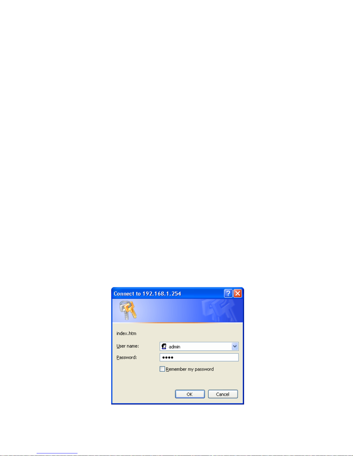
Subnet Mask, Default Gateway in the switch, then save the setting and execute the browser program
with http:// IP_Address_ of_ switch, then you may access the switch with following dialogue below.
Then type user name and password to get further service. To find out more operation in this mode,
please refer the instructions in chapter 3 of this manual to perform all function you want.
Page 11
- 11 -
1.3.3 Telnet management
In addition to local terminal mode operation, FMX-24NZ switch supports remote management
through Telnet over network or even over internet for that environment without browser. In this mode,
user also has to do the same setting as required in in-band management to the IP Configuration before
executing the Telnet program. Again, after proper setting to the switch, save the setting and connect
your Ethernet cable from your PC to any port of the Ethernet Switch, then you can simply typing as
following at the command line to access the switch:
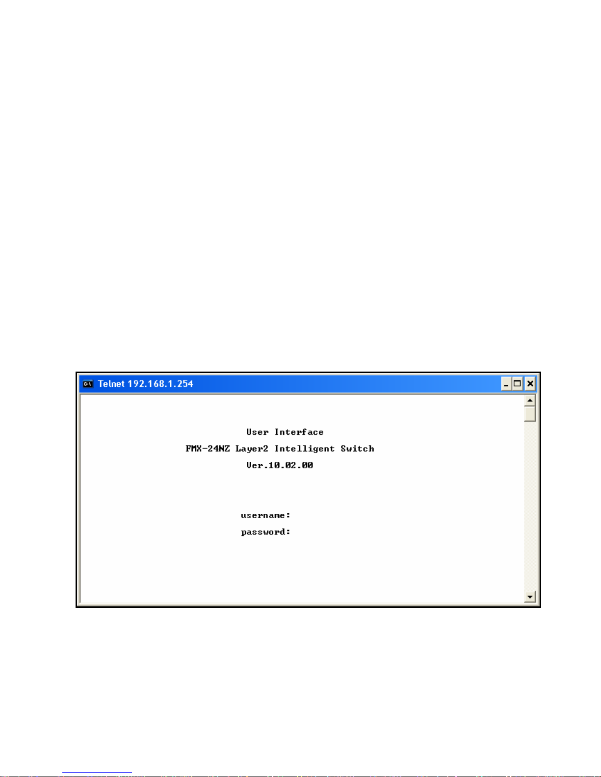
Telnet IP_Address_of_Switch
The following dialogue below appears. Type user name and password to get further service. To find
out more operation in this mode, please refer the instructions in chapter 3 of this manual to perform
all function you want.
Page 12

- 12 -
1.4 LED indicators information
There are many LEDs on the front panel of switch, after the power on, these LEDs will reflect the
current status truly within the switch, we explain below:
There is one power LED on the left side of front panel, whenever power is applied, it lights with
green, below it, there is Diagnostic LED, it will go blinking during the power-on diagnostics. There
are two more FAN status LEDs aside the power LEDs, the upper one indicate the left fan status inside
the switch, it vanishes when fan works normally, and will goes RED while fan is stop or with
malfunction, the lower one indicates the same for the fan at right side within the switch.
Each RJ-45 of 10/100M is with two LEDs built-in on its upper corner, left one indicates link status
and activity, while the right one indicates the speed information.
Each RJ-45 of 10/100/1000M for gigabit module (optional) is somewhat different. Upper yellow LED
indicates for 10M LINK, middle green LED indicates for 100M LINK, but for 1000M, or Gigabit,
both upper and middle LEDs are lit when gigabit port is link with other Gigabit port.
Status LED Color
Solid Blinking
Power
Green Turn solid green when power is
applied to this device.
N/A
DIAG
Green Successful diagnostic. during power on diagnostics
FAN
Red Left side fan fail. N/A
LINK/ACT
Green Successful connection with Fast
Ethernet.
Sending , Receiving or
collision packets
Green Successful connection with
100Mbps Fast Ethernet.
N/A
10/100M
Vanish Successful connection with
10Mbps Fast Ethernet.
N/A
Page 13
- 13 -
2. Web Management Function
2.1. Web Management Home Overview
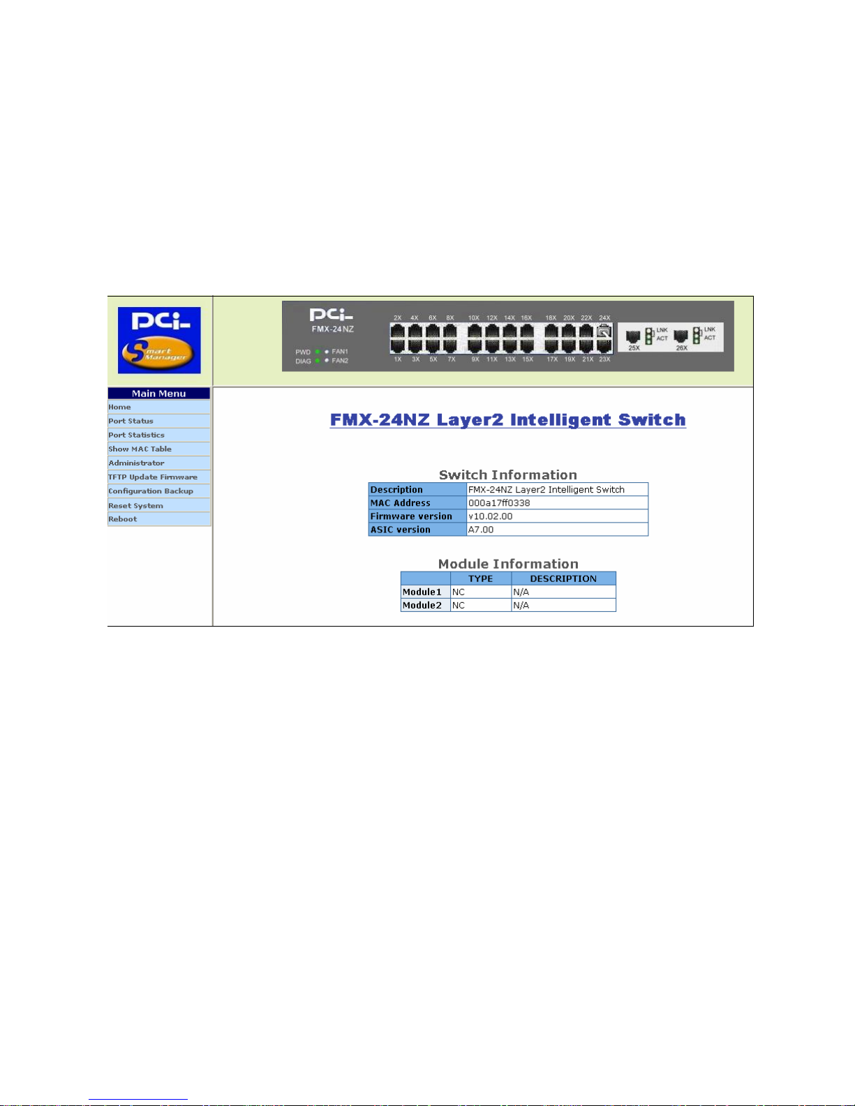
This is a Home Page.
At this page, you may see the basic switch information and module information. All information in
these fields is read-only. That is, user can’t modify its contents.
Description: Display the name of device type.
MAC Address: The unique hardware address assigned by manufacturer (default)
Firmware Version: Display the switch’s firmware version.
ASIC Version: Display the switch’s ASIC version.
On the top of web page, there is a link status from image of front panel; every port will be with a
connector icon if this port is really linked with others, you also may click the function that listed at
left. Below is the explanation of each function:
2-2. Port status
2-3. Port Statistics
2-4. Show MAC Table
Page 14
- 14 -
2-5. Administrator
2-6. TFTP Update Firmware
2-7. Configuration Backup
2-8. Reset System
2-9. Reboot
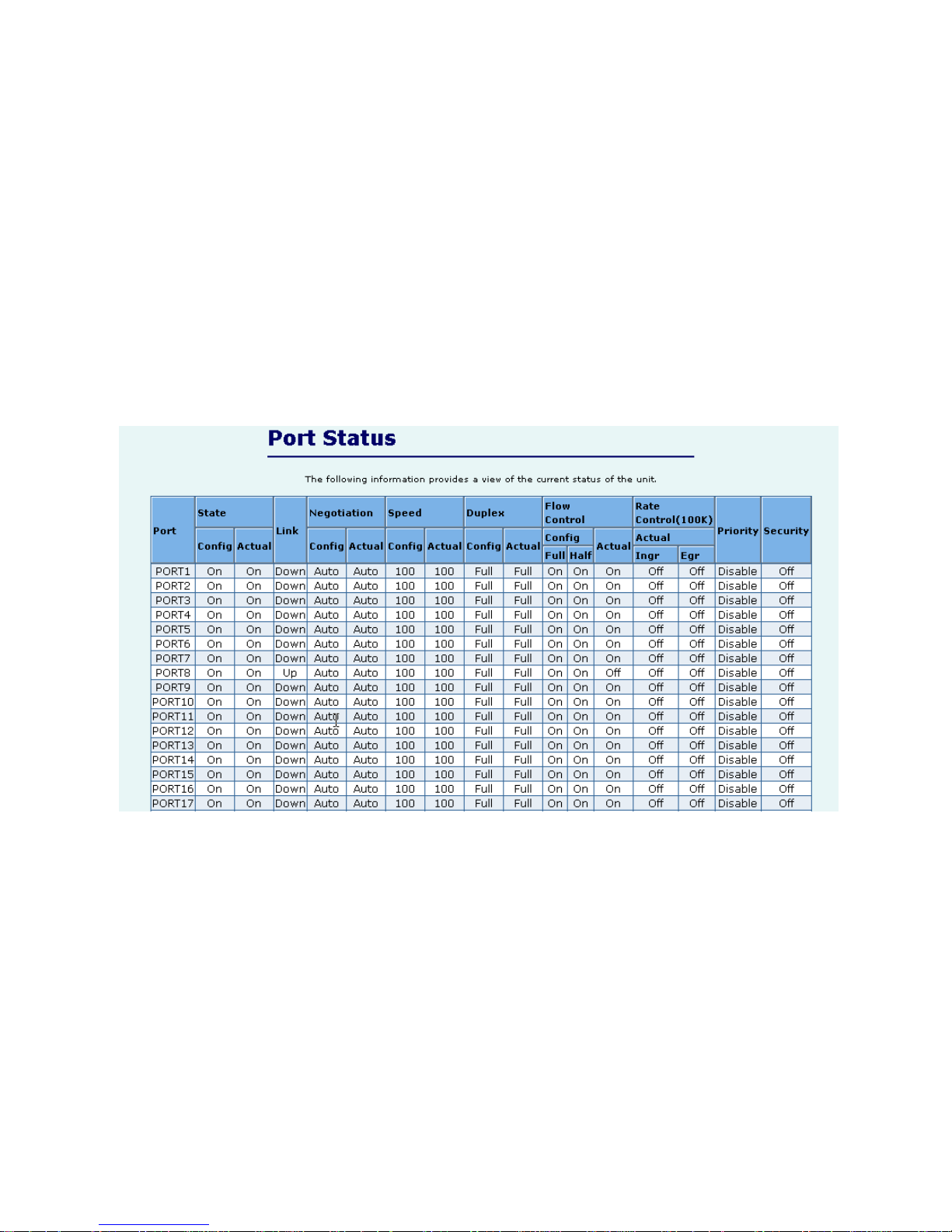
2.2. Port status
This page provides current status of every port that depends on user’s setting and the negotiation
result.
1. State: Display port statuses: disable or enable. “Unlink” will be treated as “off”.
2. Link Status: Down means “No Link”, UP means “Link”.
3. Auto Negotiation: Display the auto negotiation mode: auto/force/Nway-force.
4. Speed status: Display 1000Mbps or 100Mbps or 10Mbps speed, port 1- 24 are 10/100Mbps, Port
25-26 are 10/100/1000Mbps.
5. Duplex status: Display full-duplex or half-duplex mode.
6. Flow Control: Full: Display the flow control is enabled or disabled in full mode.
Half: Display the backpressure is enabled or disabled in half mode.
7. Rate Control: Display the rate control setting.
Ingr: Display the port effective ingress rate of user setting.
Egr: Display the port effective egress rate of user setting.
8. Port Security: Display the port security is enabled or disabled.
Page 15
- 15 -
9. Config: Display the state of user setting.
10. Actual: Display the negotiation result.
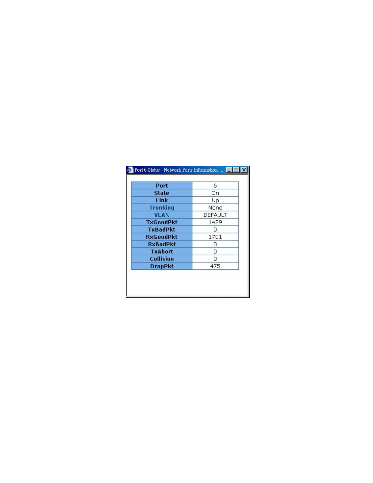
2.2.1 single port counter and status
User can also click the any port directly on the front panel of Home Page
to get single port Status which is shown below.
Page 16
- 16 -
2.3. Port Statistics
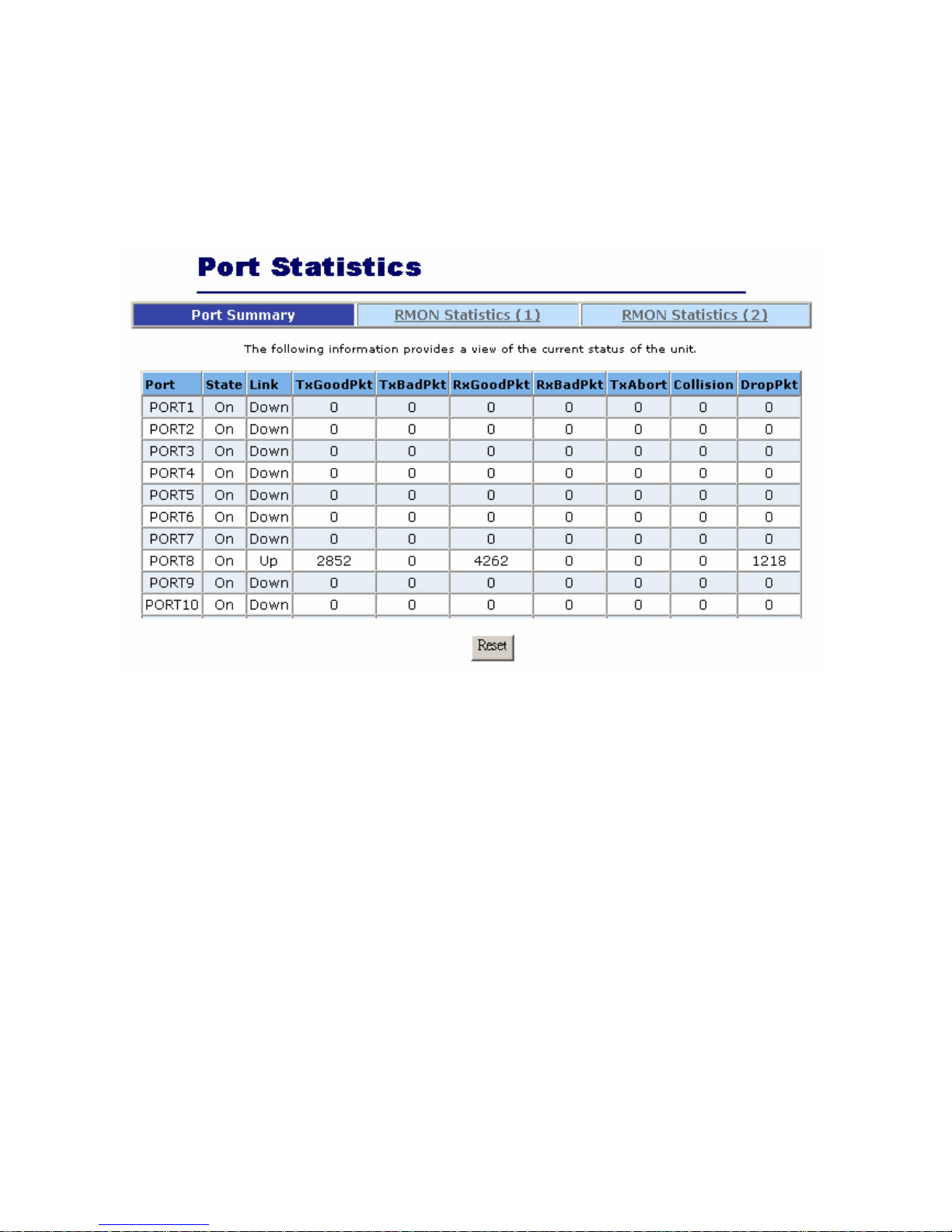
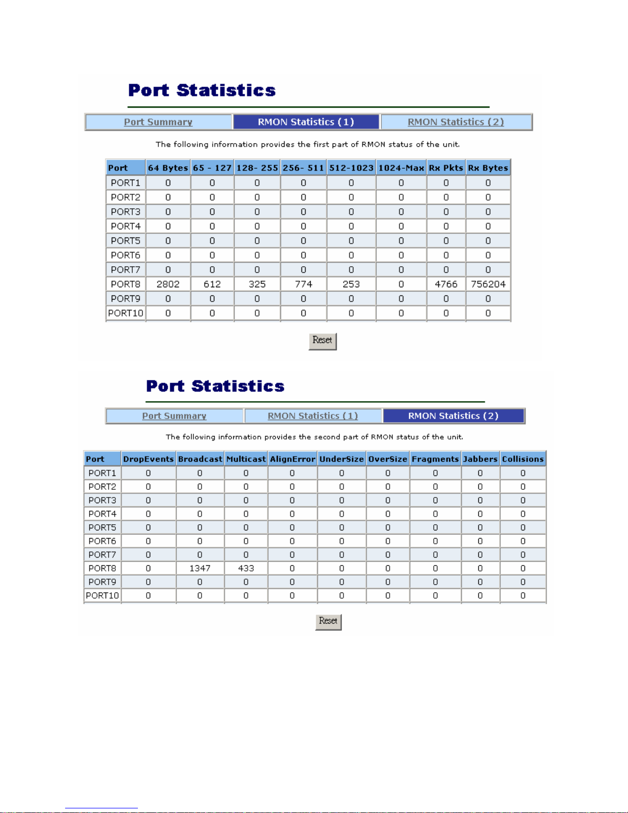
There are three pages the switch provides for user to monitor the statistics of network traffic: Port
Summary, RMON Statistics(1), RMON Statistics(2).
The Above information provides a summary of the current switch’s status, including on/off state, link
status, good or bad packets of transmitting and receiving, packets of transmitting abort, packets of
collision and drop packets.
The following two pages provide the statistics of RMON 1,2,3,9 groups. The first part collects the
information about packets of frame size within ranges of 64 , 65-127, 128-255, 256-511, 512-1023, and
1024-1518 bytes, the total received packets and the total receives bytes.
The second part collects the information about drop events, broadcast packets, multicast packets,
alignment errors, undersize packets, oversize packets , fragments, jabbers and collisions.
Press “Reset” button to clear all the counter.
Page 17
- 17 -
Page 18
- 18 -
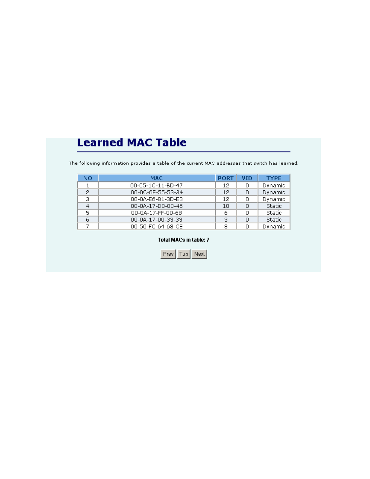
2.4. Show MAC Table
The following information provides a table of the current MAC address that the switch has learned.
Press “Prev” or “Next” button will browse previous 50 or next 50 items. The “Top” button will re-list
the table from the first MAC.
A sorting function is implemented here. Clicking header on the top of table will bring a new sorted
list of current content in the order of its title. For instance, clicking the “MAC” on the top of table will
refresh the table by the index of “MAC”.
Page 19

- 19 -
2.5. Administrator
There are many management functions can be set or performed if you click the
Administrator on Home Page, including:
IP address/Subnet Mask/Gateway
Switch settings
Console port information
Port Configuration
Trunking
IGMP and MAC Filter
VLAN Configuration
Spanning Tree
Port Mirror
SNMP/Trap Manager
Security Manager
802.1x Configuration
Ping
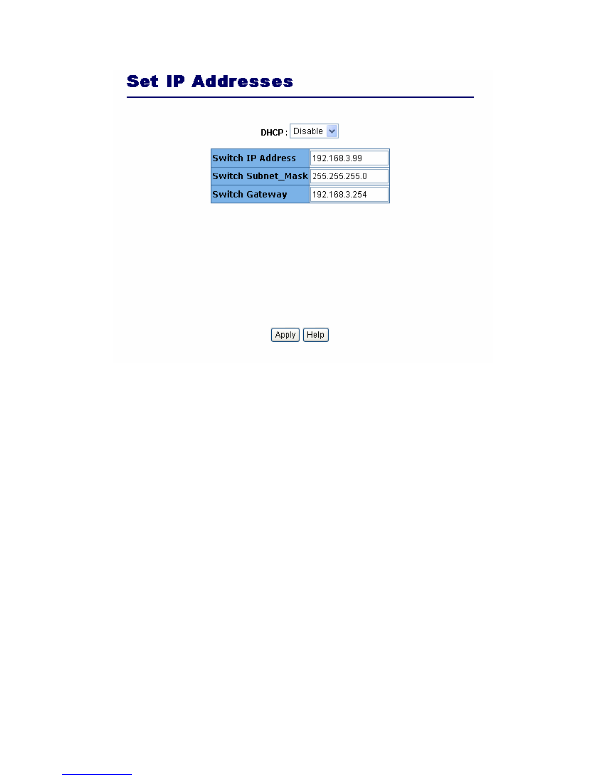
2.5.1. IP Address/Subnet Mask/Gateway
User can modify the switch IP Settings by filling with the new value, then clicks “apply” button to
confirm (save) his setting, then he must reboot switch, then new IP configuration value will be
activated.
Page 20
- 20 -
2.5.2 Switch Setting
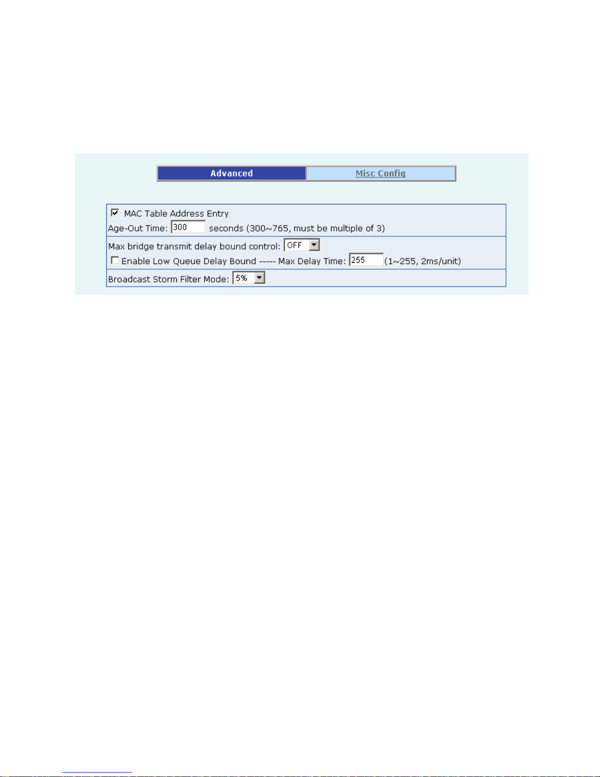
2.5.2.1 Advanced
Miscellaneous Setting:
MAC Address Age-out Time: Type the number of seconds that an inactive MAC address remains in the
switch's address table. The valid range is 300~765 seconds. Default is 300 seconds.
Max bridge transit delay bound control: Limit the packets queuing time in switch. If enable, the
packets queued exceed will be drop. These valid values are 1sec, 2 sec, and 4 sec and off. Default is 1
seconds.
NOTE: Make sure of “Max bridge transit delay bound control” is enabled before enable Delay Bound,
because Enable Delay Bound must be work under “Max bridge transit delay bound control is enabled”
situation.
Page 21
- 21 -
Broadcast Storm Filter: To configure broadcast storm control, enable it and set the upper threshold for
individual ports. The threshold is the percentage of the port's total bandwidth used by broadcast traffic.
When broadcast traffic for a port rises above the threshold you set, broadcast storm control becomes
active. The valid threshold value is 5%, 10%, 15%, 20%, 25% and off.
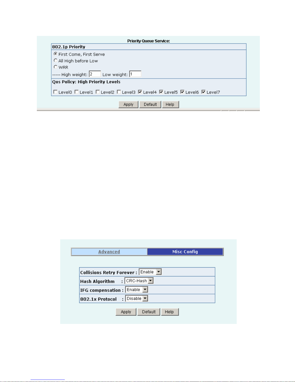
Priority Queue Service settings:
First Come, First Serve: The sequence of packets sent is depending on arrive orders.
All High before Low: The high priority packets sent before low priority packets.
WRR: Weighted Round Robin. Select the preference given to packets in the switch's high-priority
queue. These options represent the number of high priority packets sent before one low
priority packet is sent. For example, 5 High:2 Low means that the switch sends 5 high-priority
packets before sending 2 low- priority packets.
Enable Delay Bound: Limit the low priority packets queuing time in switch. Default Max Delay
Time is 255ms. If the low priority packet stays in switch exceed Max Delay
Time, it will be sent. The valid range is 1-255ms.
Qos Policy: High Priority Levels: 0~7 priority level can map to high or low queue.
Page 22
- 22 -
2.5.2.2 Misc Config
Collisions Retry Forever:
Disable – In half duplex, collision-retry maximum is 48 times and packet will be
dropped if collision still happen.
Enable – In half duplex, if happen collision will retry forever.
Hash Algorithm: Choose algorithms, CRC-Hash or DirectMap, to maintain MAC address table.
IFG Compensation: Enable or disable inter-frame gap (IFG) compensation.
802.1x Protocol: Enable or disable 802.1x protocol.
Page 23
- 23 -
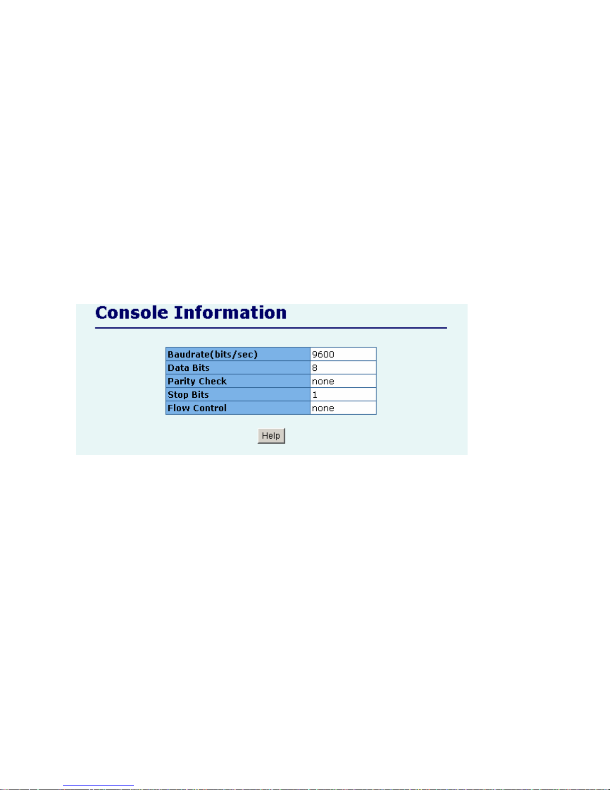
2.5.3 Console Port Information
Console is a standard UART interface to communicate with Serial Port.
User can use windows HyperTerminal program to link the switch. Connect To -> Configure:
Bits per seconds: 9600
Data bits: 8
Parity: none
Stop Bits: 1
Flow control: none
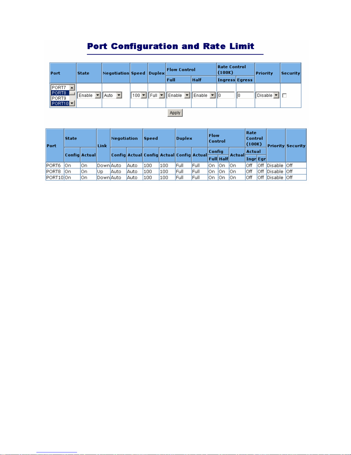
2.5.4 Port Controls
User may modify or change mode operation in this page.
Page 24
- 24 -
1. State: User can disable or enable this port control.
2. Auto Negotiation: User can set auto negotiation mode is Auto, Nway (specify the speed/duplex on
this port and enable auto-negotiation), Force of per port.
3. Speed:
User can set 100Mbps or 10Mbps speed on Port1~Port24.
User can set 1000Mbps, 100Mbps or 10Mbps speed on Port25~Port26 (depend on module card
mode).
4. Duplex: User can set full-duplex or half-duplex mode of per port.
5. Flows control:
Full: User can set flow control function is enable or disable in full mode.
Half: User can set backpressure is enable or disable in half mode.
6. Rate Control: port1 ~ port 24, supports by-port ingress and egress rate control. For example, assume
port 1 is 10Mbps, users can set its effective egress rate at 1Mbps and ingress rate at 500Kbps. Device
will perform flow control or backpressure to confine the ingress rate to meet the specified rate.
Ingress: Type the port effective ingress rate. The valid range is 0 ~ 1000. The unit is 100K.
0: disable rate control.
1 ~ 1000: valid rate value
Egress: Type the port effective egress rate. The valid range is 0~1000. The unit is 100K.
0: disable rate control.
1 ~ 1000: valid rate value.
7. Port Priority: Enable or disable the port priority function. There are two priorities (high or low)
provided if port priority is enabled.
Page 25

- 25 -
8. Port Security: A port in security mode will be “locked” without permission of address learning. Only
the incoming packets with SMAC already existing in the address table can be forwarded normally.
User can disable the port from learning any new MAC addresses, then use the static MAC addresses
screen to define a list of MAC addresses that can use the secure port. Enter the settings, then click
Apply button to change on this page.
Page 26
- 26 -
2.5.5 Trunking
The Link Aggregation Control Protocol (LACP) provides a standardized means for exchanging
information between Partner Systems on a link to allow their Link Aggregation Control instances to reach
agreement on the identity of the Link Aggregation Group to which the link belongs, move the link to that
Link Aggregation Group, and enable its transmission and reception functions in an orderly manner. In
conclusion, Link aggregation lets you group up to eight consecutive ports into a single dedicated
connection. This feature can expand bandwidth to a device on the network. LACP operation requires
full-duplex mode, more detail information refers to IEEE 802.3ad
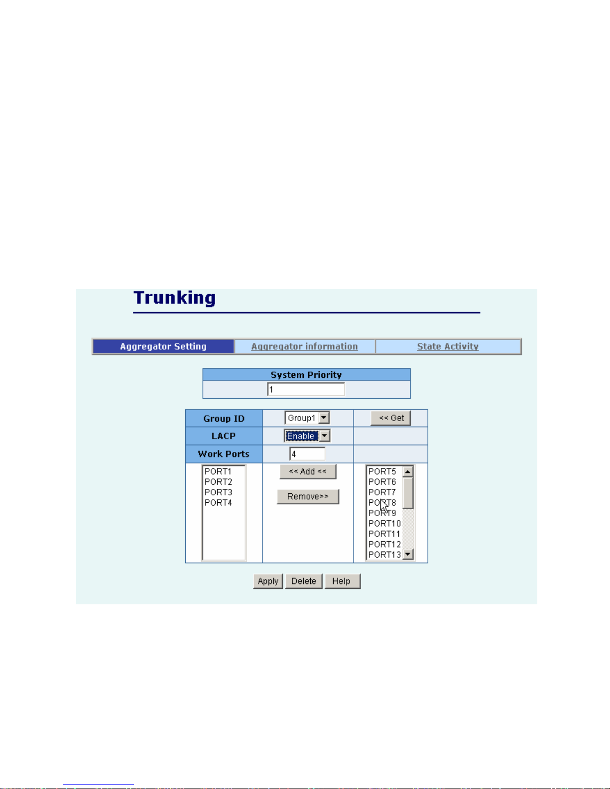
2.5.5.1 Aggregator setting
1. System Priority: A value used to identify the active LACP. The switch with the lowest value has the
highest priority and is selected as the active LACP. Valid value is 1~65535.
2. Group ID: There are seven trunk groups to provide configure. Choose the "group id" and click
"Get".
3. LACP: If enable, the group is LACP static trunking group. If disable, the group is local static
trunking group. All ports support LACP dynamic trunking group. If connecting to the device that also
Page 27
- 27 -
supports LACP, the LACP dynamic trunking group will be created automatically.
4. Work ports: Allow max four ports can be aggregated at the same time. If LACP static trunking
group, the exceed ports is standby and able to aggregate if work ports fail. If local static trunking
group, the number must be as same as the group member ports.
5. Select the ports to join the trunking group. Allow max four ports can be aggregated at the same time.
6. If LACP enable, you can configure LACP Active/Passive status in each port on State Activity page.
7. Click Apply.
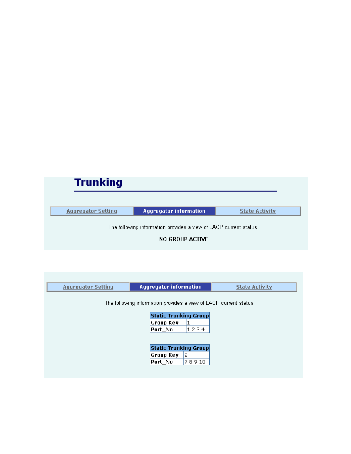
2.5.5.2 Aggregator Information
When you are setting LACP aggregator, you can see relation information in here.
1. This page is no group active. LACP don’t working.
2. This page is Static Trunking groups.
3. This page is Actor and Partner trunking one group.
Page 28
- 28 -
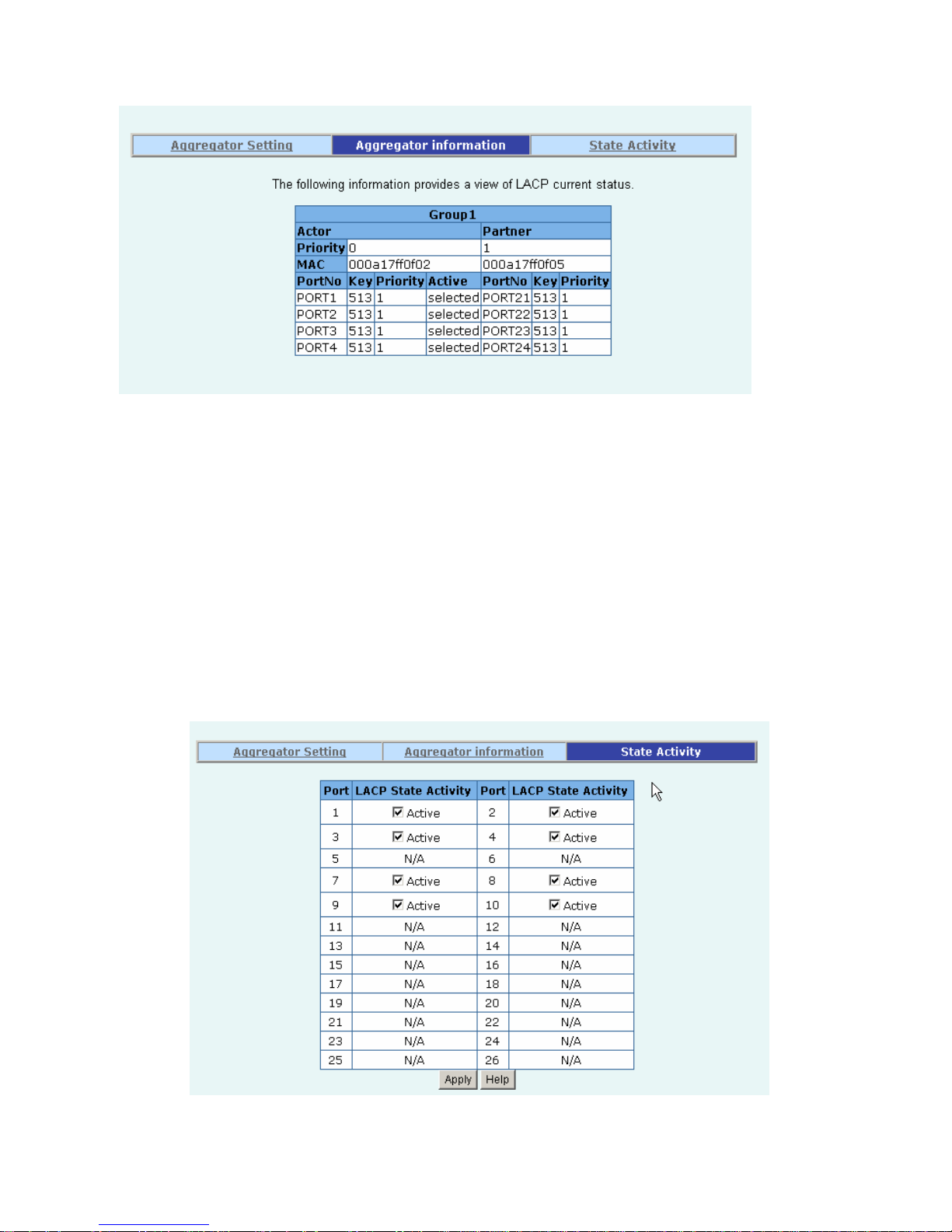
2.5.5.3 State Activity
Active (select): The port automatically sends LACP protocol packets.
N/A (no select): The port does not automatically sends LACP protocol packets, and responds only if it
receives LACP protocol packets from the opposite device.
1. A link that has either two active LACP ports or one active port can perform dynamic LACP trunking.
A link has two N/A LACP ports will not perform dynamic LACP trunking because both ports are
waiting for and LACP protocol packet from the opposite device.
2. If you are active LACP’s actor, when you are select trunking port, the active status will be created
automatically.
Page 29
- 29 -
2.5.6 IGMP and MAC Filter
2.5.6.1. IGMP Snooping
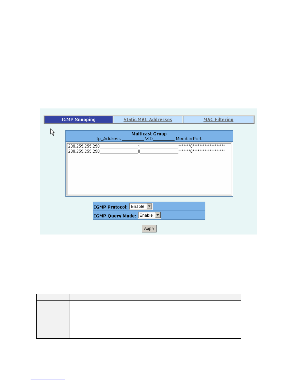
The FMX-24NZ switch supports multicast IP. One can enable IGMP protocol on this web page, and then
display the IGMP snooping information on this page. There are all multicast groups, VIDs and member
ports in the list. IP multicast addresses range from 224.0.0.0 through 239.255.255.255.
The Internet Group Management Protocol (IGMP) is an internal protocol of the Internet Protocol (IP)
suite.
IGMP can manage the multicast traffic if the members (switches, router or other network devices) of
group support IGMP. With IGMP enable, the member ports will detect IGMP queries, report packets and
manage the IP multicast traffic through the switch.
IGMP have three fundamental types of message as follows:
Message Description
Query
A message sent from the queries (IGMP router or switch) asking for a
response from each host belonging multicast group.
Report
A message sent by a host to the queries to indicate that the host wants to be or
is a member of a given group indicated in the report message.
Leave Group
A message sent by a host to the queries to indicate that the host has quit being
a member of a specific multicast group.
Page 30
- 30 -
2.5.6.2. Static MAC Address
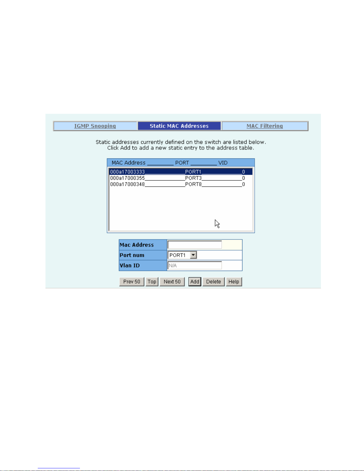
When you add a static MAC address, it remains in the switch's address table, regardless of whether the
device is physically connected to the switch. This saves the switch from having to re-learn a device's
MAC address when the disconnected or powered-off device is active on the network again.
1. At the main menu, click administrator ÆFilter Database ÆStatic MAC Address.
2. In the MAC address box, enter the MAC address to and from which the port should permanently
forward traffic, regardless of the device’s network activity.
3. In the Port Number box, enter a port number.
4. If tag-based (IEEE 802.1Q) VLANs are set up on the switch, static addresses are associated with
individual VLANs. Type the VID (tag-based VLANs) to associate with the MAC address.
5. Click the Add.
6. Click the “Prev 50” will list the previous 50 MAC addresses.
7. Click the “Top” will refresh the list from the first entry.
8. Click the “Next 50” will list the next 50 MAC addresses.
Page 31
- 31 -
2.5.6.3 MAC filtering
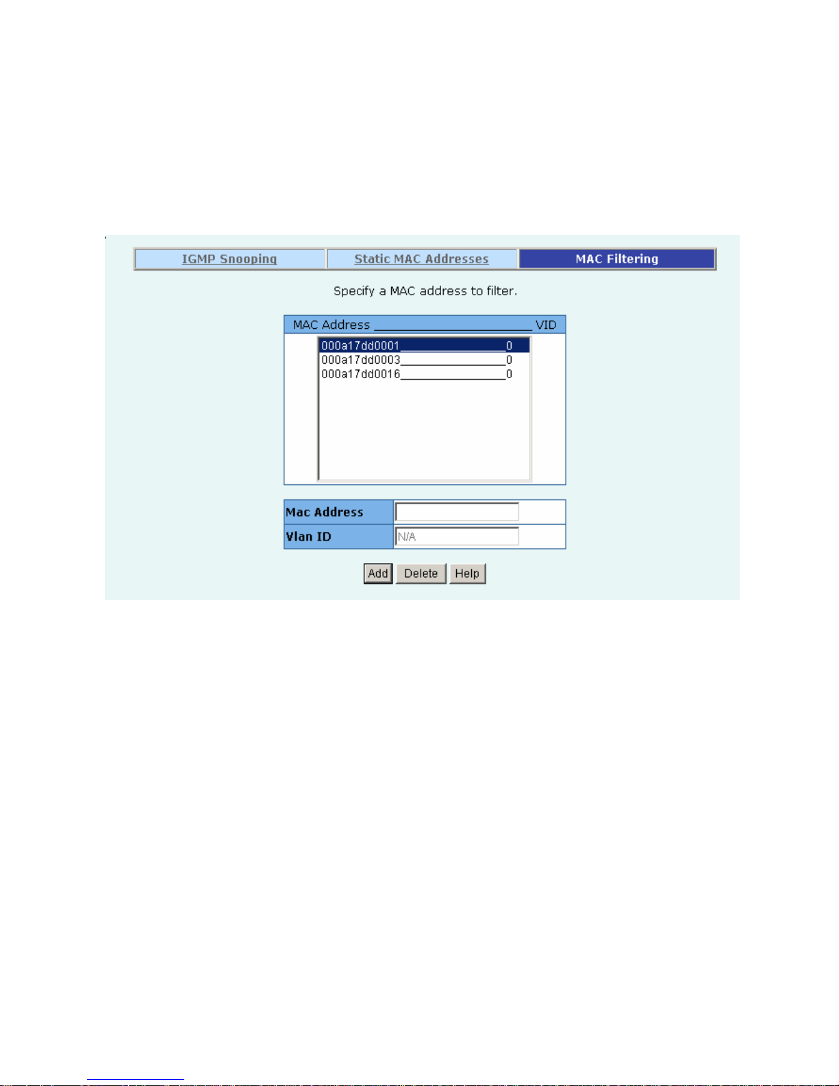
MAC address filtering allows the switch to drop unwanted traffic. Traffic is filtered based on the
destination addresses.
1. In the MAC Address box, enter the MAC address that wants to filter.
2. If tag-based (802.1Q) VLAN are set up on the switch, in the VLAN ID box, type the VID to associate
with the MAC address.
3. Click the Add.
4. Choose the MAC address that you want to delete and then click the Delete.
Page 32
- 32 -
2.5.7. VLAN configuration
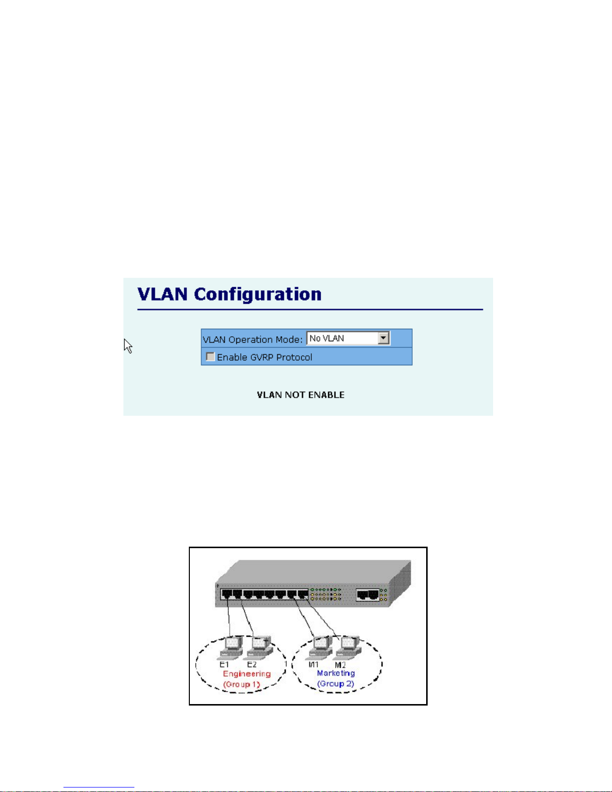
A Virtual LAN (VLAN) is a logical network grouping that limits the broadcast domain. It allows you to
isolate network traffic so only members of the VLAN receive traffic from the same VLAN members.
Basically, creating a VLAN from a switch is logically equivalent of reconnecting a group of network
devices to another Layer 2 switch. However, all the network devices are still plug into the same switch
physically.
The FMX-24NZ switch supports port-based, 802.1Q (tagged-based) and protocol-base VLAN in web
management page. In the default configuration, VLAN support is disabling.
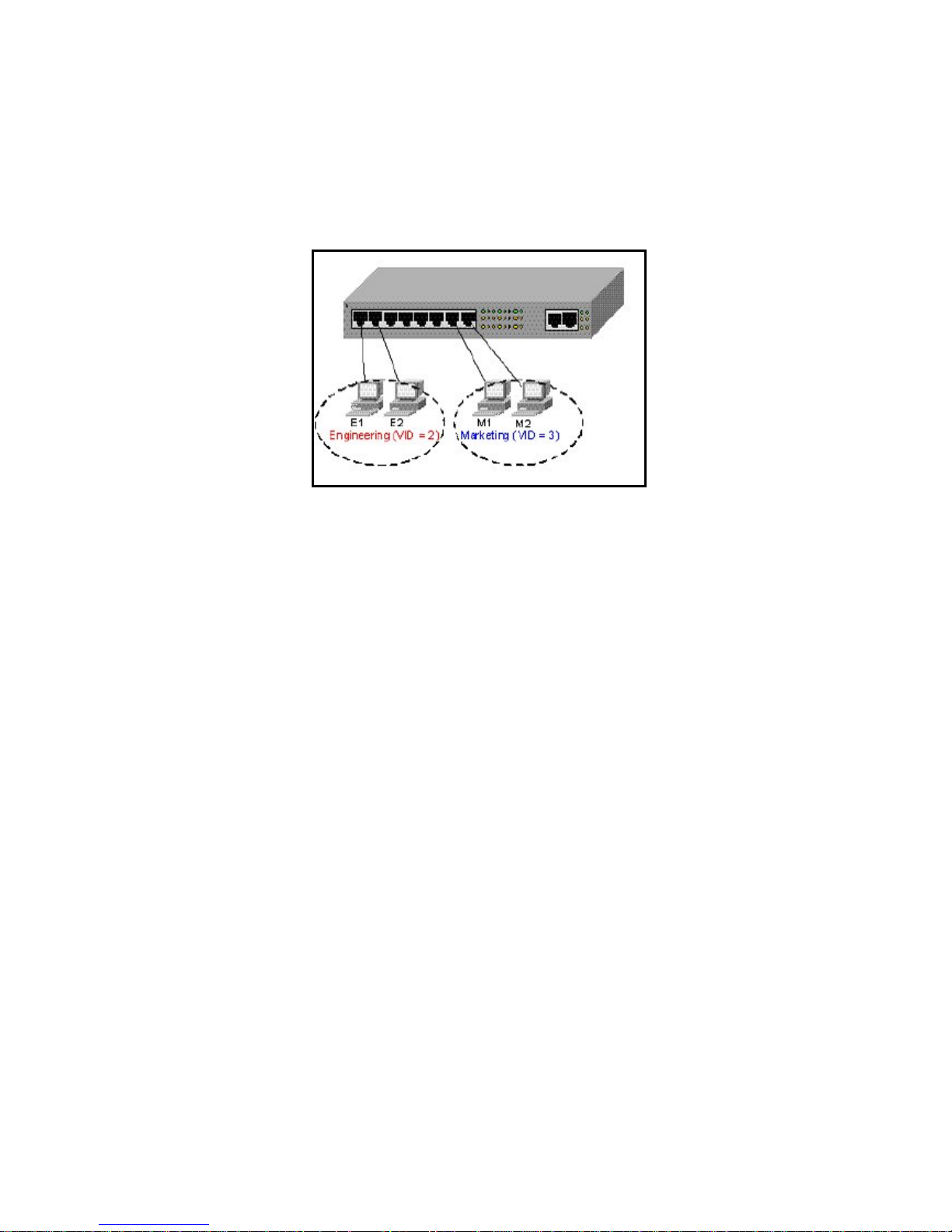
Support Port-based VLAN
Packets can only be broadcast among members of the same VLAN group. Note all unselected ports are
treated as belonging to another single VLAN. If the port-based VLAN enabled, the VLAN-tagging is
ignored.
Page 33
- 33 -
Support Tag-based VLAN (IEEE 802.1Q VLAN)
Tagged-based VLAN is an IEEE 802.1Q specification standard. Therefore, it is possible to create a
VLAN across devices from different switch venders. IEEE 802.1Q VLAN uses a technique to insert a
“tag” into the Ethernet frames. Tag contains a VLAN Identifier (VID) that indicates the VLAN numbers.
Support Protocol-based VLAN
In order for an end station to send packets to different VLANs, it itself has to be either capable of tagging
packets it sends with VLAN tags or attached to a VLAN-aware bridge that is capable of classifying and
tagging the packet with different VLAN ID based on not only default PVID but also other information
about the packet, such as the protocol.
FMX-24NZ switch will support protocol-based VLAN classification by means of both built-in
knowledge of layer 2 packet formats used by selected popular protocols, such as Novell IPX and
AppleTalk’s Ether Talk, and some degree of programmable protocol matching capability.
Page 34
- 34 -
2.5.7.1. Port Based VLAN
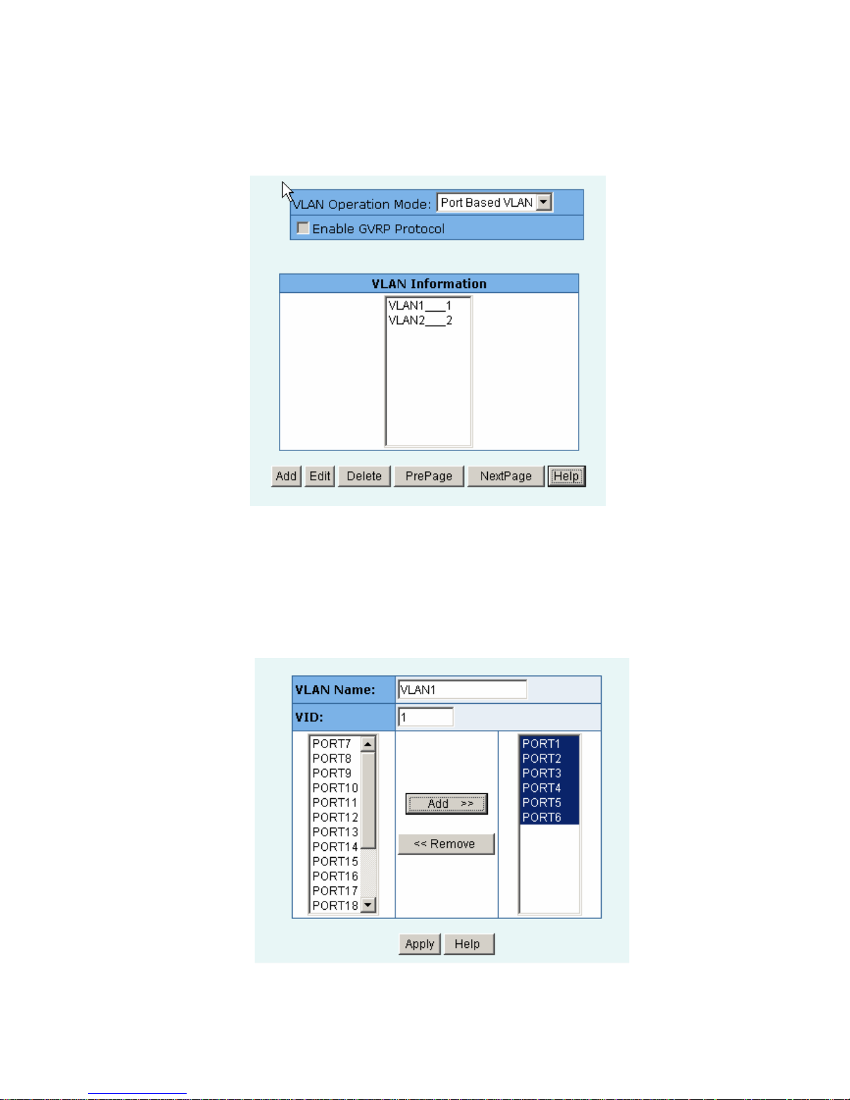
1. Click Add to create a new VLAN group.
2. Enter the VLAN name, group ID and select the members for the new VLAN.
3. Click Apply.
4. If there are many groups that over the limit of one page, you can click the “Next Page” to view other
VLAN groups.
NOTE: If the trunk groups exist, you can see it (ex: TRK1, TRK2…) in select menu of ports, and you
can configure it is the member of the VLAN or not.
Page 35
- 35 -
2.5.7.2. 802.1Q VLAN
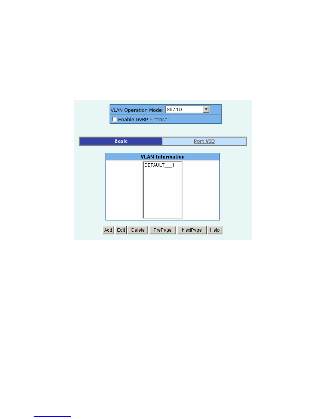
This page, user can create Tag-based VLAN, and enable or disable GVRP protocol.
There are 256 VLAN groups to provide configure. Enable 802.1Q VLAN, the all ports on the switch
belong to default VLAN, VID is 1. The default VLAN can’t be deleted.
GVRP (GARP [Generic Attribute Registration Protocol] VLAN Registration Protocol)
GVRP allows automatic VLAN configuration between the switch and nodes. If the switch is
connected to a device with GVRP enabled, you can send a GVRP request using the VID of a VLAN
defined on the switch, the switch will automatically add that device to the existing VLAN.
Page 36
- 36 -
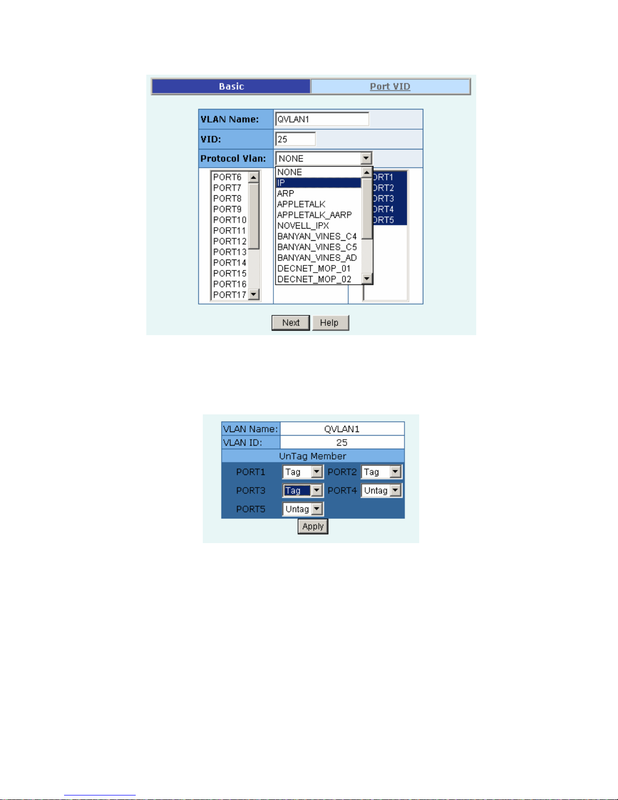
◆Basic
Create a VLAN and add tagged member ports to it.
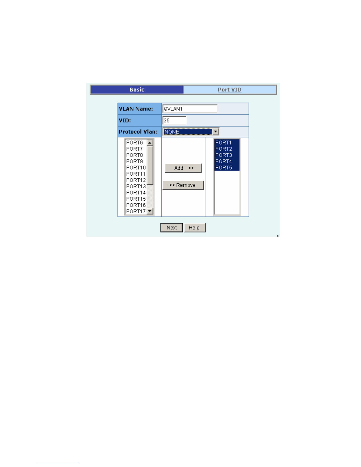
1. From the main menu, click Administrator ÆVLAN configuration, click Add then you will see the
page as follow.
2. Type a name for the new VLAN.
3. Type a VID (between 2-4094). The default is 1.
4. Choose the protocol type.
We support 802.1v with the implementation of Port-and-Protocol-based VLAN classification.
User can combine the field “Protocol Vlan” and the field of the port number to form a new
VLAN group.
NOTE:
IEEE 802.1v provides user to classify the packet through untagged port. There are two possible
strategies of the 802.1v supporting: Port-based VLAN and Port-and-Protocol-based VLAN. We
can support both Port-based VLAN and Port-and-Protocol-based VLAN with our product. User
set the VID to mark the packet from untagged port. Then, the packet can be scheduled by the way
of the IEEE 802.1q.
Page 37
- 37 -
5. From the Available ports box, select ports to add to the switch and click “Add >>”. If the trunk
groups exist, you can see it in here (ex: TRK1, TRK2…), and you can configure it is the member
of the VLAN or not.
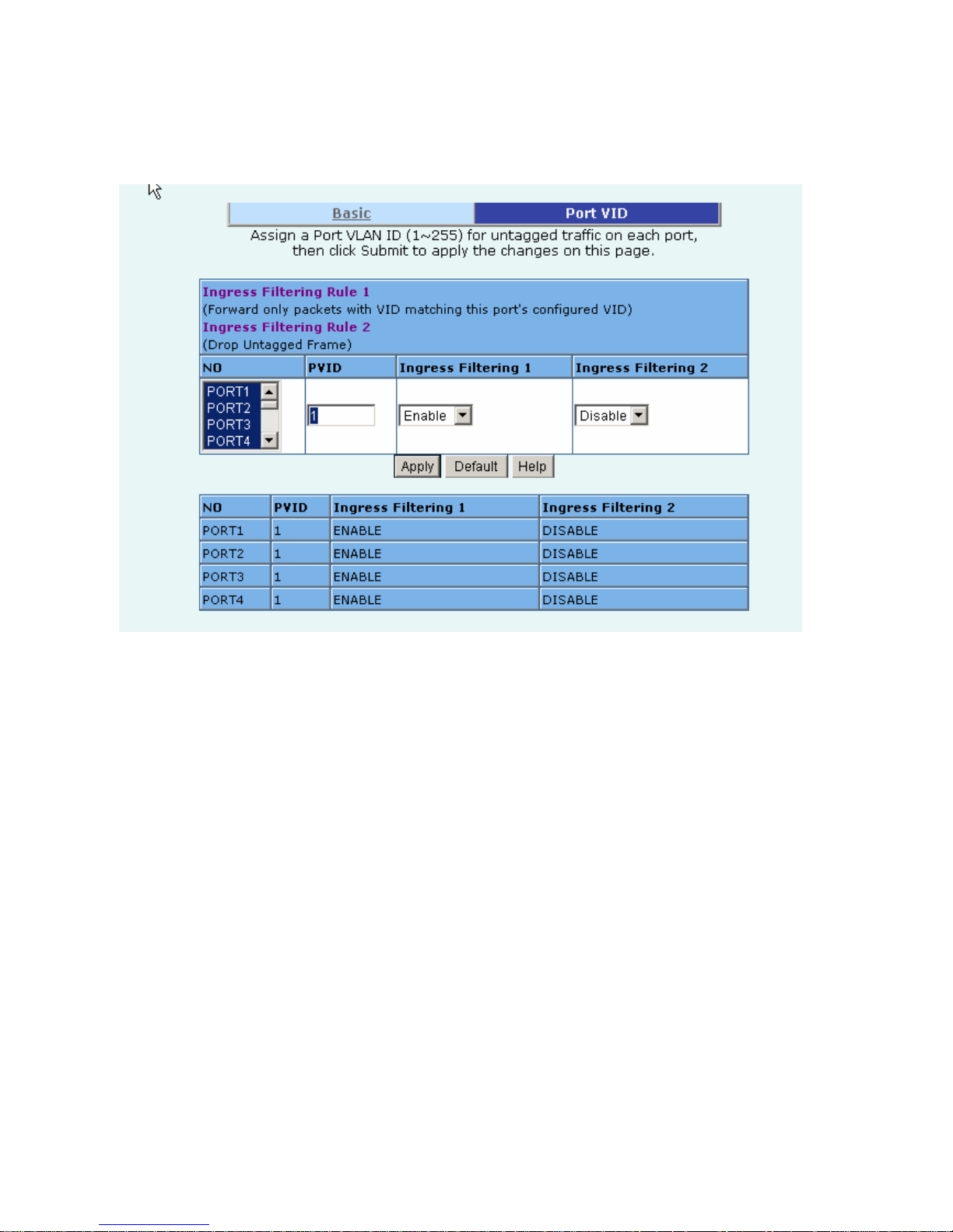
6. Click Next. Then you can view the page as follow:
7. Uses this page to set the outgoing frames are VLAN-Tagged frames or no. Then click Apply.
Tag: outgoing frames with VLAN-Tagged.
Untag: outgoing frames without VLAN-Tagged.
Page 38
- 38 -
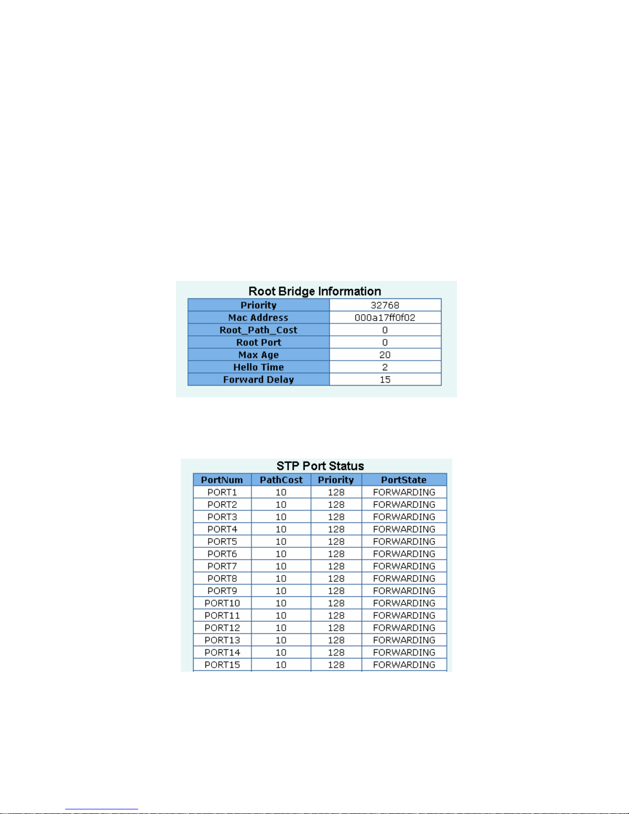
◆Port VID
Configure port VID settings
From the main Tag-based (IEEE 802.1Q) VLAN page, click Port VID Settings.
Port VID (PVID)
Set the port VLAN ID that will be assigned to untagged traffic on a given port. This feature is useful
for accommodating devices that you want to participate in the VLAN but that don’t support tagging.
FMX-24NZ switch each port allows user to set one PVID, the range is 1~255, default PVID is 1. The
PVID must as same as the VLAN ID that the port belong to VLAN group, or the untagged traffic will
be dropped.
Ingress Filtering
Ingress filtering lets frames belonging to a specific VLAN to be forwarded if the port belongs to that
VLAN. FMX-24NZ switch has two ingress filtering rule as follows:
Ingress Filtering Rule 1: A forward only packet with VID matching this port’s configured VID.
Ingress Filtering Rule 2: Drop Untagged Frame.
Page 39
- 39 -
2.5.8. Spanning Tree
The Spanning-Tree Protocol (STP) is a standardized method (IEEE 802.1D) for avoiding loops in
switched networks. Enable STP to ensure that only one path at a time is active between any two nodes
on the network.
You can enable Spanning-Tree Protocol on web management’s switch setting advanced item, select
enable Spanning-Tree protocol. We are recommended that you enable STP on all switches ensures a
single active path on the network.
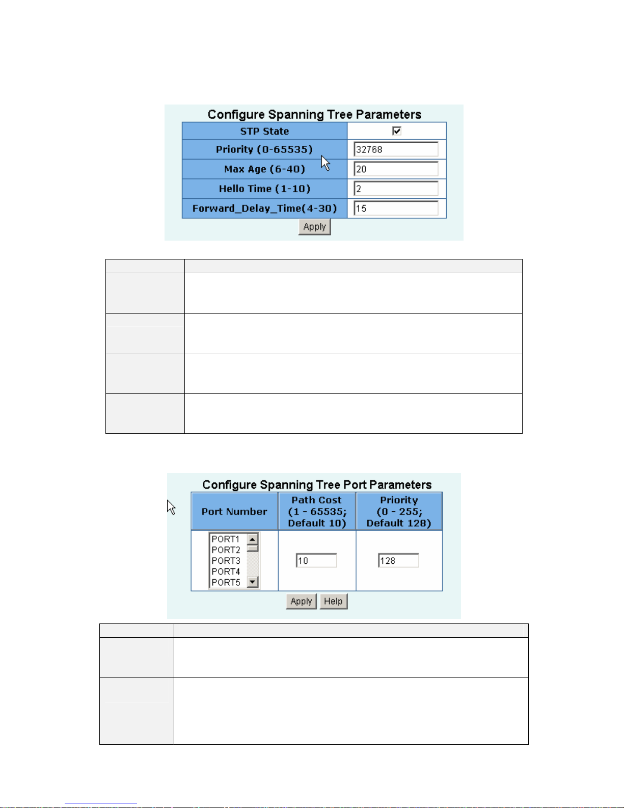
1. You can view spanning tree information about the Root Bridge. Such as follow screen.
2. You can view spanning tree status about the switch. Such as follow screen.
Page 40
- 40 -
3. You can setting new value for STP parameter, then click set Apply button to modify
Parameter Description
Priority
You can change priority value, A value used to identify the root bridge.
The bridge with lowest value has the highest priority and is selected as
the root. Enter a number 1 through 65535.
Max Age
You can change Max Age value, The number of second bridge waits
without receiving Spanning-Tree Protocol configuration messages
before attempting a reconfiguration. Enter a number 6 through 40.
Hello Time
You can change Hello time value, the number of seconds among the
transmission of Spanning-Tree Protocol configuration messages. Enter a
number 1 through 10.
Forward
Delay time
You can change forward delay time, The number of seconds a port waits
before changing from its Spanning-Tree Protocol learning and listening
states to the forwarding state. Enter a number 4 through 30.
4. The following parameter can be configured on each port , click set Apply button to modify
Parameter Description
Port Priority
You can make it more or less likely to become the root port, the rage is
0-255,default setting is 128
The lowest number has the highest priority.
Path Cost
Specifies the path cost of the port that switch uses to determine which port
are the forwarding ports
the lowest number is forwarding ports, the rage is 1-65535 and default
value base on IEEE802.1D
10Mb/s = 50-600 100Mb/s = 10-60 1000Mb/s = 3-10
Page 41
- 41 -
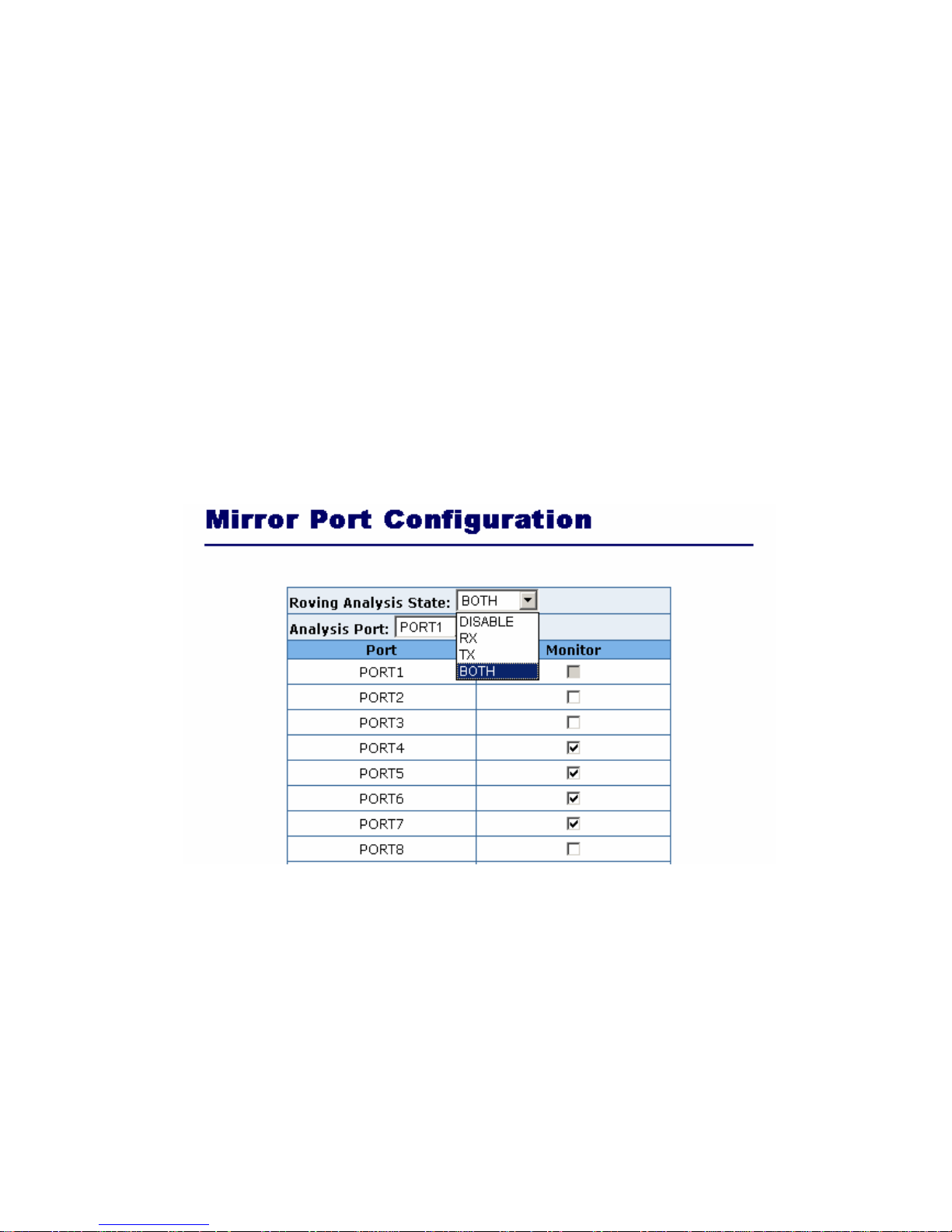
2.5.9. Port Mirror
The Port Mirror is a method for monitor traffic in switched networks. Traffic through ports can be
monitored by one specific port. That is, traffic goes in or out monitored ports will be duplicated into
mirror port.
1. Mirror Mode: Press Space key to set mirror mode: Disable \Rx \Tx \Both.
2. Monitoring Port: It’ means mirror port can be used to see all monitors port traffic. You can
connect mirror port to LAN analyzer or netxray.
3. Monitored Port: The ports you want to monitor. All monitor port traffic will be copied to mirror
port. You can select max 25 monitor ports in the switch. User can choose which port that they
want to monitor in only one mirror mode.
If you want to disable the function, you must select monitor port to none.
Page 42
- 42 -
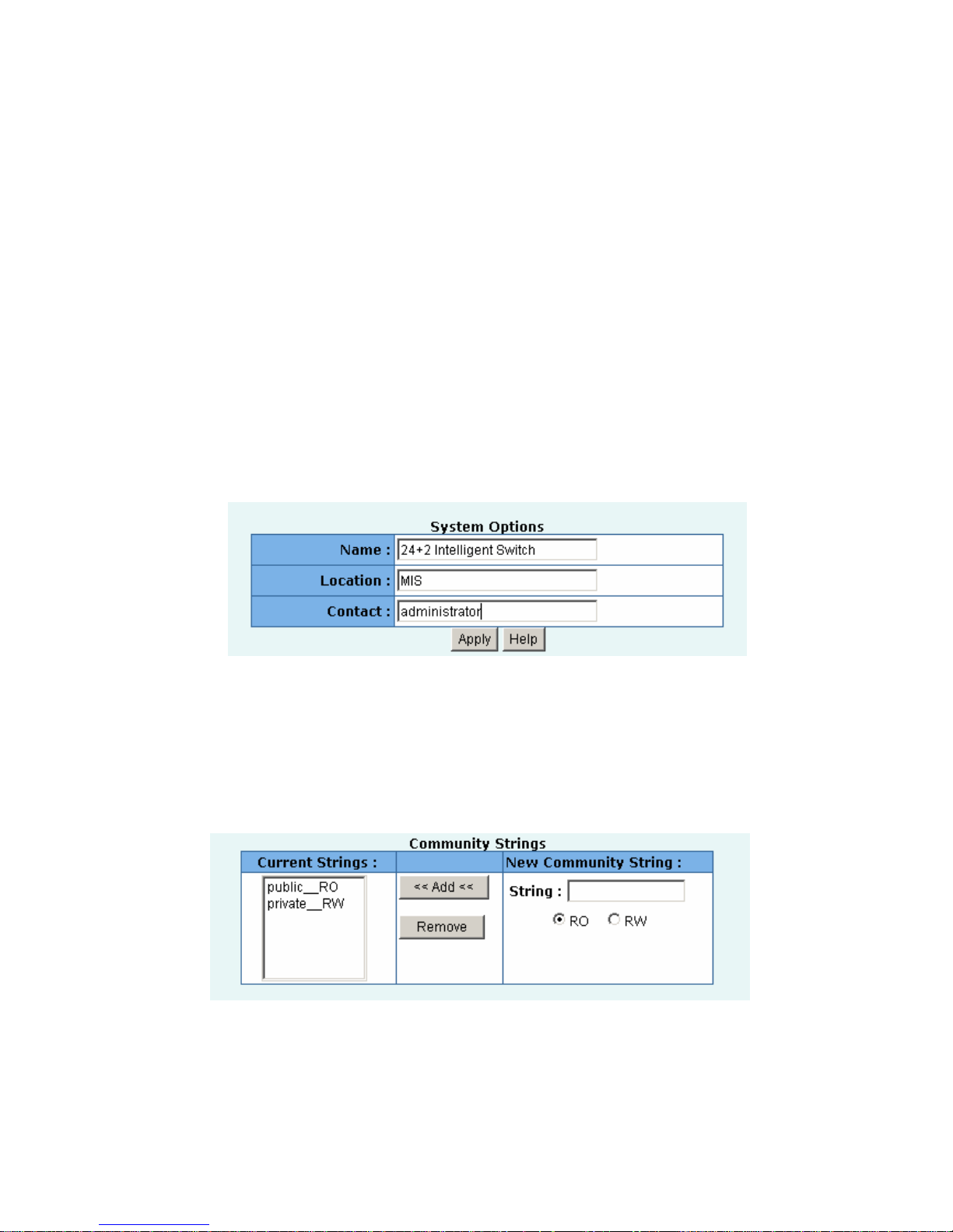
2.5.10. SNMP/Trap Manager
Any Network Management platform running the simple Network Management Protocol (SNMP) can
manage the switch, provided the Management Information Base (MIB) is installed correctly on the
management station. The SNMP is a Protocol that governs the transfer of information between
management station and agent.
1. System Options: Use this page to define management stations as trap managers and to enter
SNMP community strings. User can also define a name, location, and contact person for the
switch. Fill in the system options data, and then click Apply to update the changes on this page.
Name: Enter a name to be used for the switch.
Location: Enter the location of the switch.
Contact: Enter the name of a person or organization.
2. Community strings serve as passwords and can be entered as one of the following:
RO: Read only. Enables requests accompanied by this string to display MIB-object information.
RW: Read write. Enables requests accompanied by this string to display MIB-object information
and to set MIB objects.
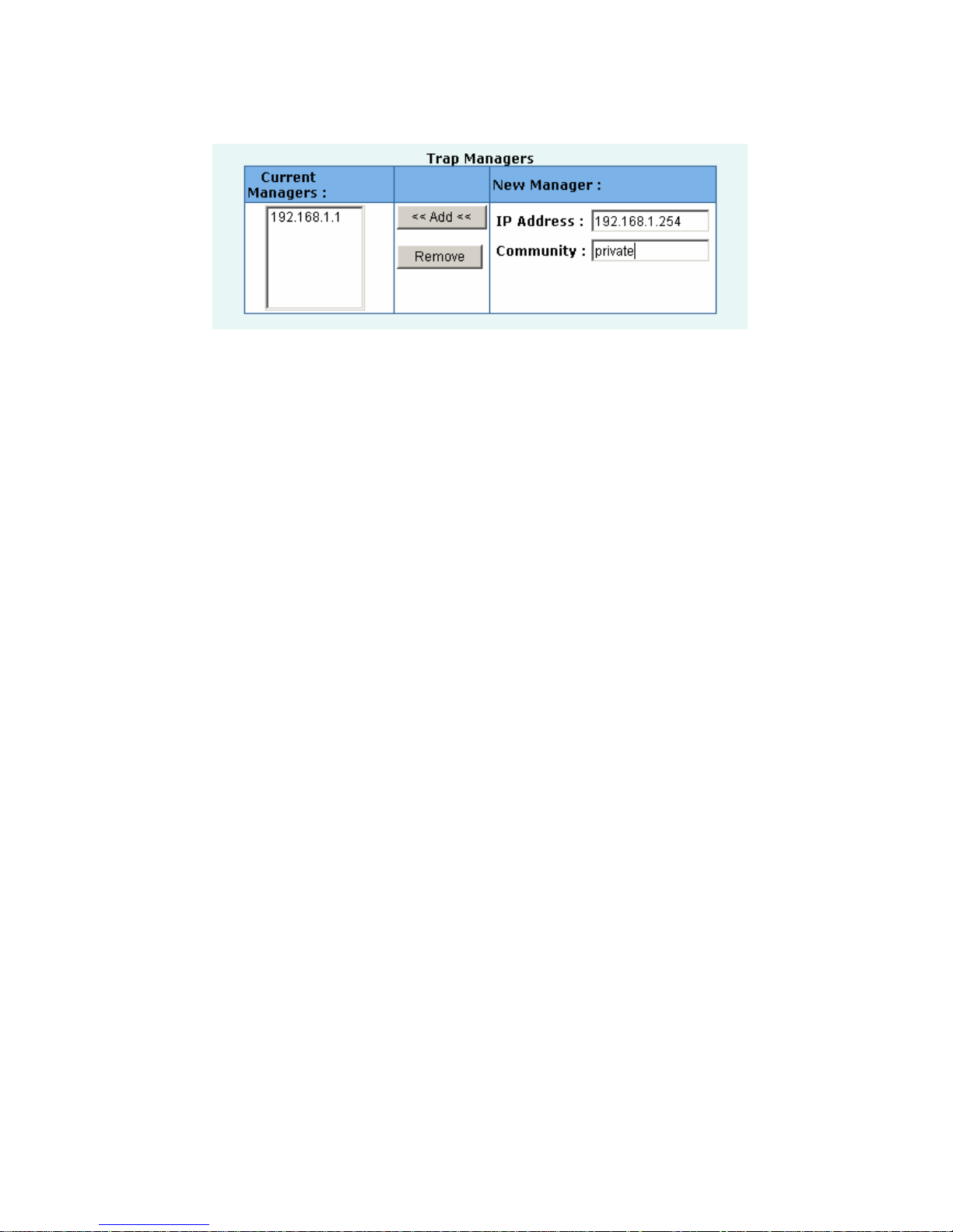
3. Trap Manager :A trap manager is a management station that receives traps, the system alerts
generated by the switch. If no trap manager is defined, no traps are issued. Create a trap manager
by entering the IP address of the station and a community string.
Page 43
- 43 -
Page 44
- 44 -
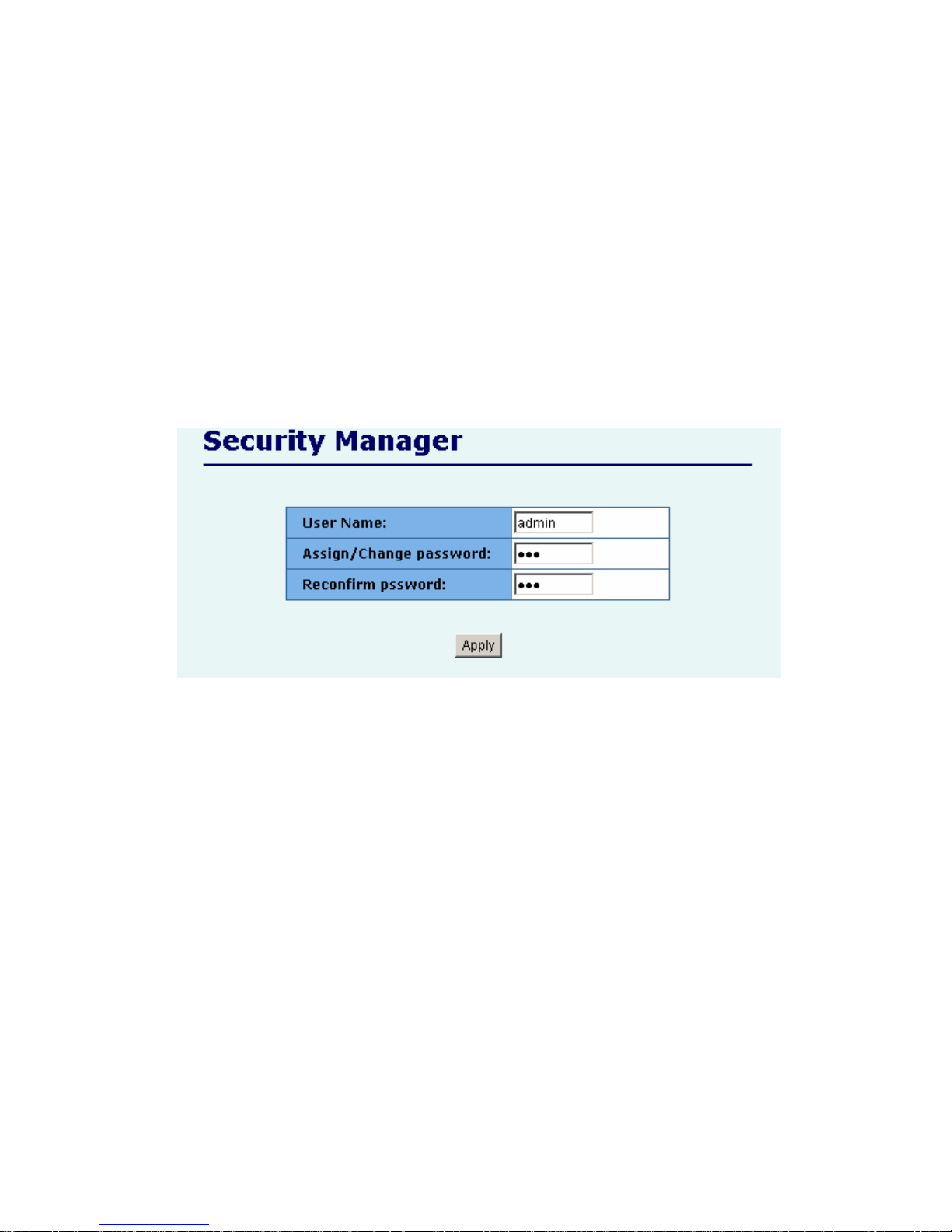
2.5.11 Security Manager
On this page, user can change user name and password with following steps.
1. User name: Type the new user name.
2. Password: Type the new password.
3. Reconfirm password: Retype the new password.
4. Click Apply.
Page 45
- 45 -
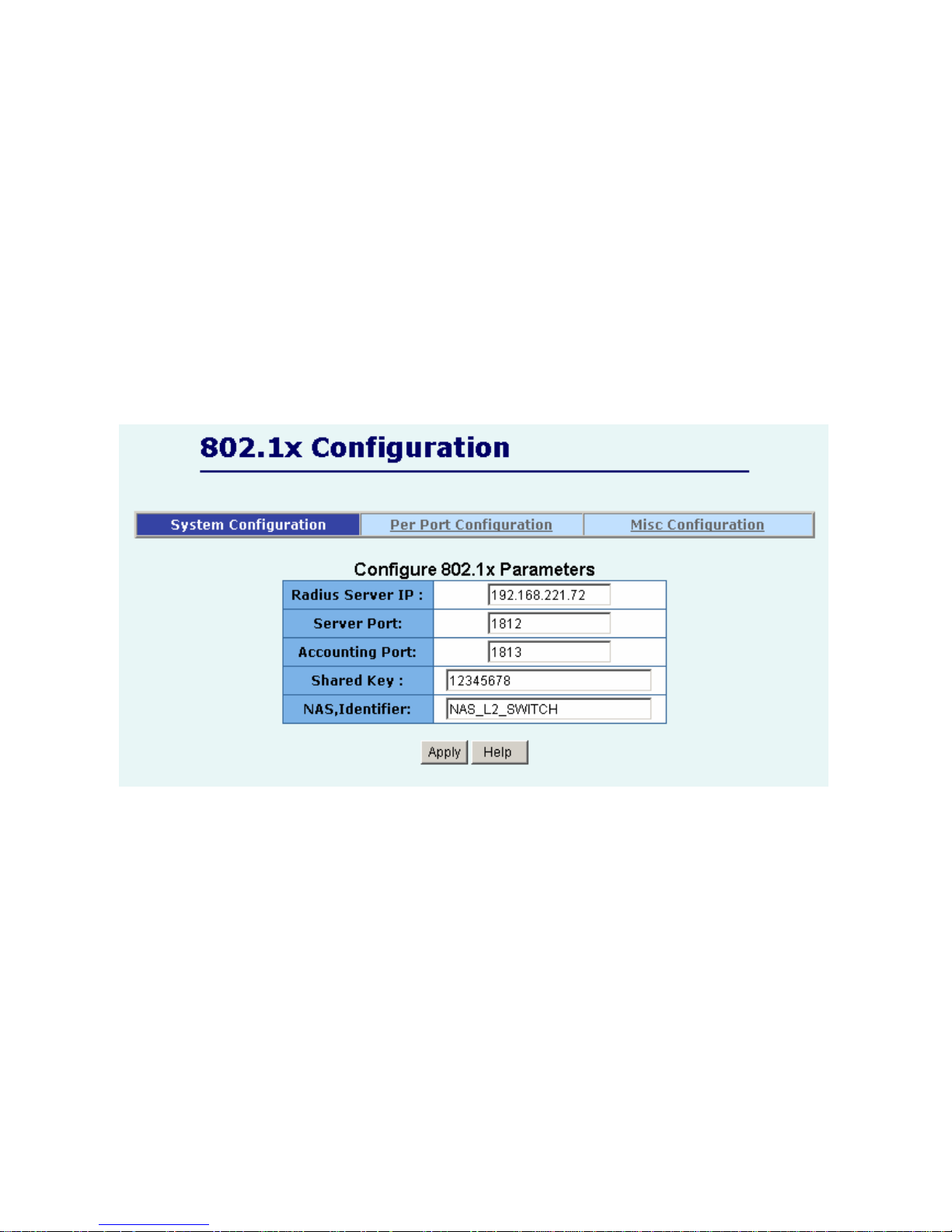
2.5.12 802.1x Configuration
System Configuration
802.1x makes use of the physical access characteristics of IEEE802 LAN infrastructures in order to
provide a means of authenticating and authorizing devices attached to a LAN port that has
point-to-point connection characteristics, and of preventing access to that port in cases in which the
authentication and authorization process fails.
To enable 802.1x, from Administrator \Switch setting \Advanced then you still to fill in the
authentication server information:
Radius Server IP Address: the IP address of the authentication server.
Server Port: The UDP port number used by the authentication server to authenticate. Accounting
Port: The UDP port number used by the authentication server to retrieve accounting information.
Shared Key: A key shared between this switch and authentication server.
NAS, Identifier: A string used to identify this switch.
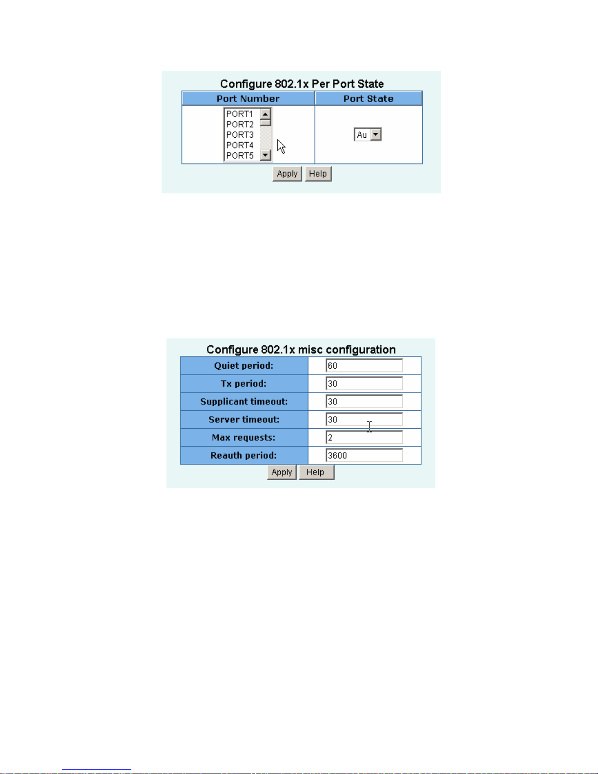
Perport Configuration
In this page, you can select the specific port and configure the Authorization State.
Each port can select four kinds of Authorization State:
Page 46
- 46 -
Fu:Force the specific port to be unauthorized.
Fa:Force the specific port to be authorized.
Au:The state of the specific port was determined by the outcome of the authentication.
No:The specific port didn't support 802.1x function.
Misc Configuration
In this page, you can change the default configuration for the 802.1x standard:
Quiet Period: Used to define periods of time during which it will not attempt to acquire a supplicant
(Default time is 60 seconds).
Tx Period: Used to determine when an EAPOL PDU is to be transmitted (Default value is 30
seconds).
Supplicant Timeout: Used to determine timeout conditions in the exchanges between the supplicant
and authentication server (Default value is 30 seconds).
Server Timeout: Used to determine timeout conditions in the exchanges between the authenticator
and authentication server (Default value is 30 seconds).
Max requests:Used to determine the number of re-authentication attempts that are permitted before
the specific port becomes unauthorized (Default value is 2 times).
Reauth Period: Used to determine a nonzero number of seconds between periodic re-authentication
off the supplications (Default value is 3600 seconds).
Page 47
- 47 -
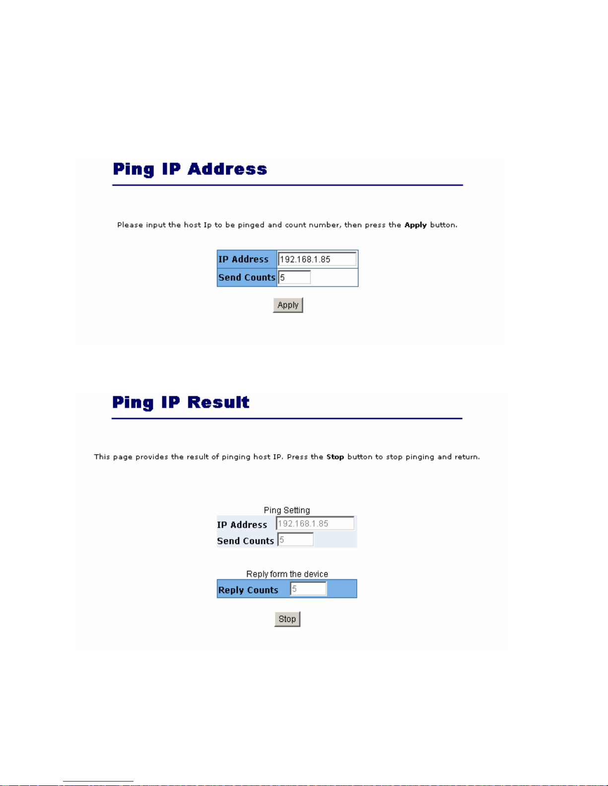
2.5.13 Ping
This switch provides a simple ping function for user to check the access of specific host.
Input the host IP and the counts of ping, then press “Apply” and the result comes as following:
User can stop pinging anytime by just press “Stop” button, and it will return to Ping IP Address page.
Page 48
- 48 -
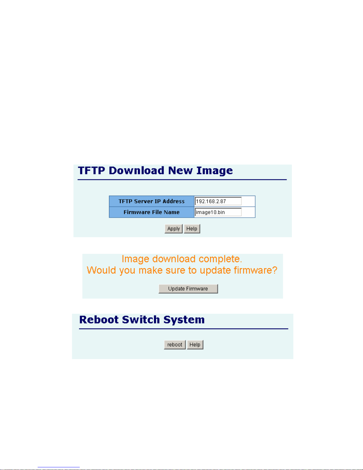
2.6. TFTP Update Firmware
1. The following menu options provide some system control functions to allow a user to update
firmware and remote boot switch system:
* Install TFTP program (such as Turbo98, or Cisco TFTP) and then execute.
* Copy updated firmware image.bin into TFTP server’s directory.
* In web management select administrator—TFTP update firmware.
* Download new image.bin file by pressing <update firmware>.
* After update finished, press <reboot> to restart switch.
Page 49
- 49 -
2.7. Configuration Backup
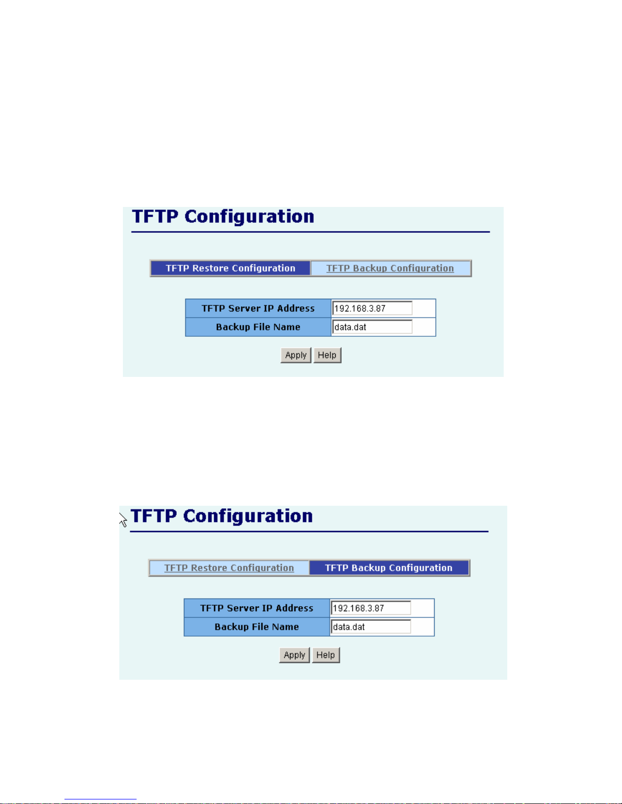
2.7.1. TFTP Restore Configuration
Use this page to set ftp server address. You can restore EEPROM value from here, but you must put
back image in ftp server, switch will download back flash image.
2.7.2. TFTP Backup Configuration
Use this page to set tftp server ip address. You can save current EEPROM value from here, then go to
the TFTP restore configuration page to restore the EEPROM value.
Page 50
- 50 -
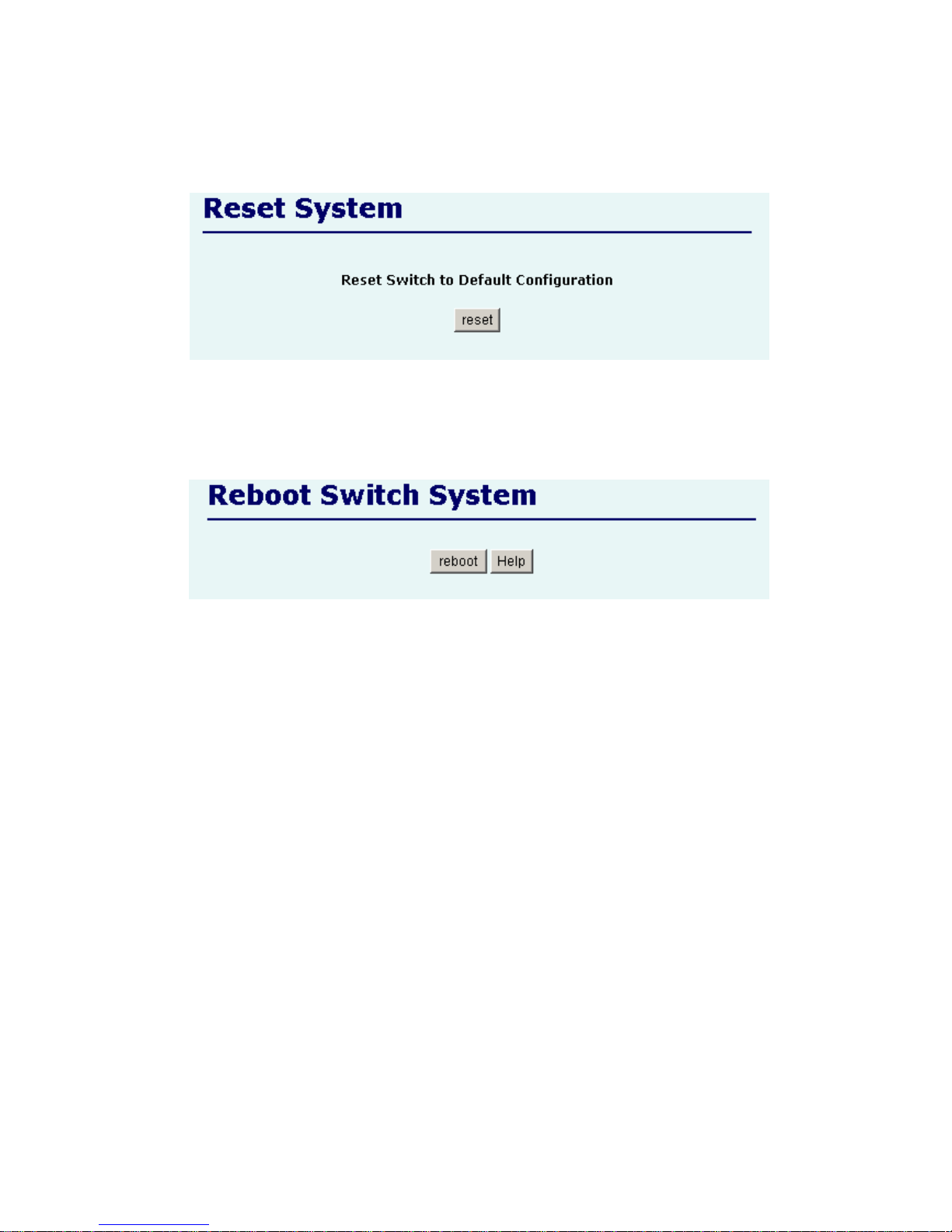
2.8. Reset System
Reset Switch to default configuration, default value as below
2.9. Reboot
Reboot the Switch in software reset.
Page 51
- 51 -
3. Console -- 1K Xmodem update
firmware
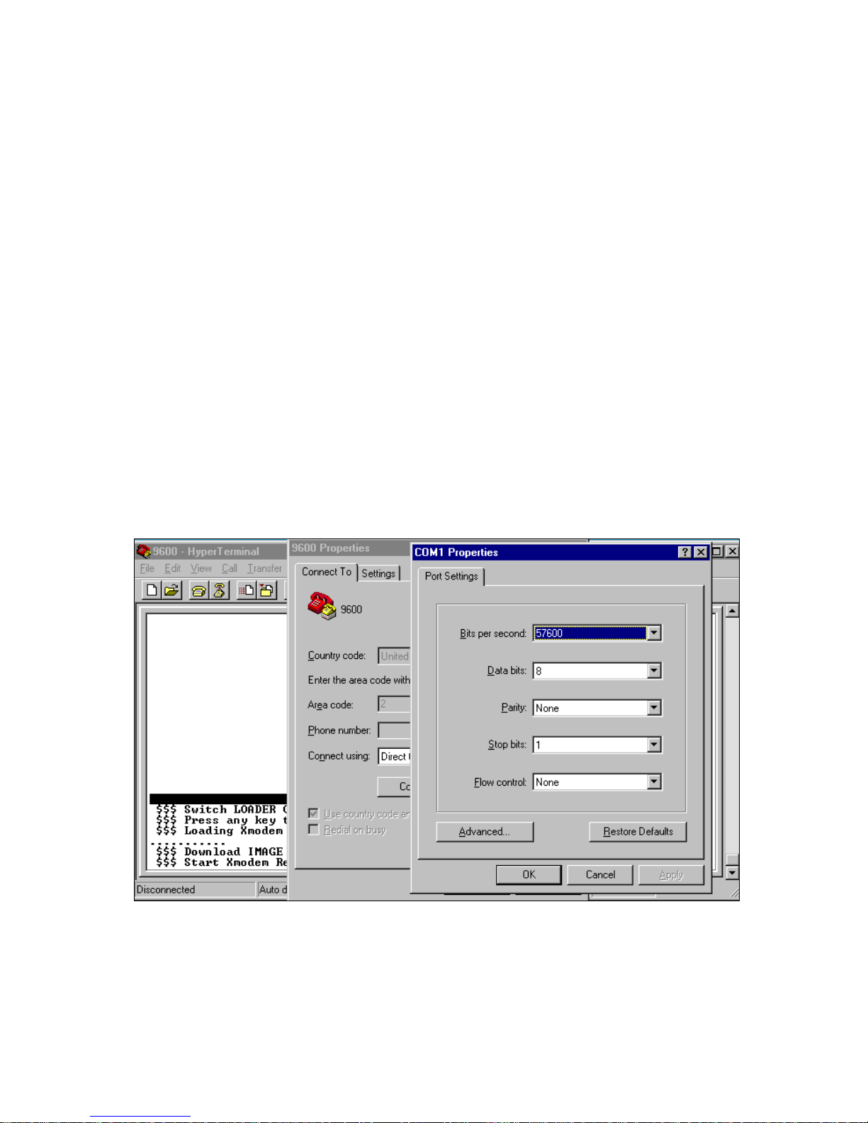
We provide the 1k X modem to update firmware on console. 1K X modem only works in 57600bps
mode. So you must change boudrate to 57600bps to download firmware.
There are 2 cases to use 1k X modem to update firmware:
a. User enters "1K X modem receiver mode" through pressing any key within 5 seconds after system
power on.
b. System automatically enters "1K X modem receiver mode" if it detects the firmware checksum
fail while booting.
1. Press disconnect button when you start 1K X modem modes.
Press File -> Properties, change boudrate to 57600bps, then press OK.
Page 52
- 52 -
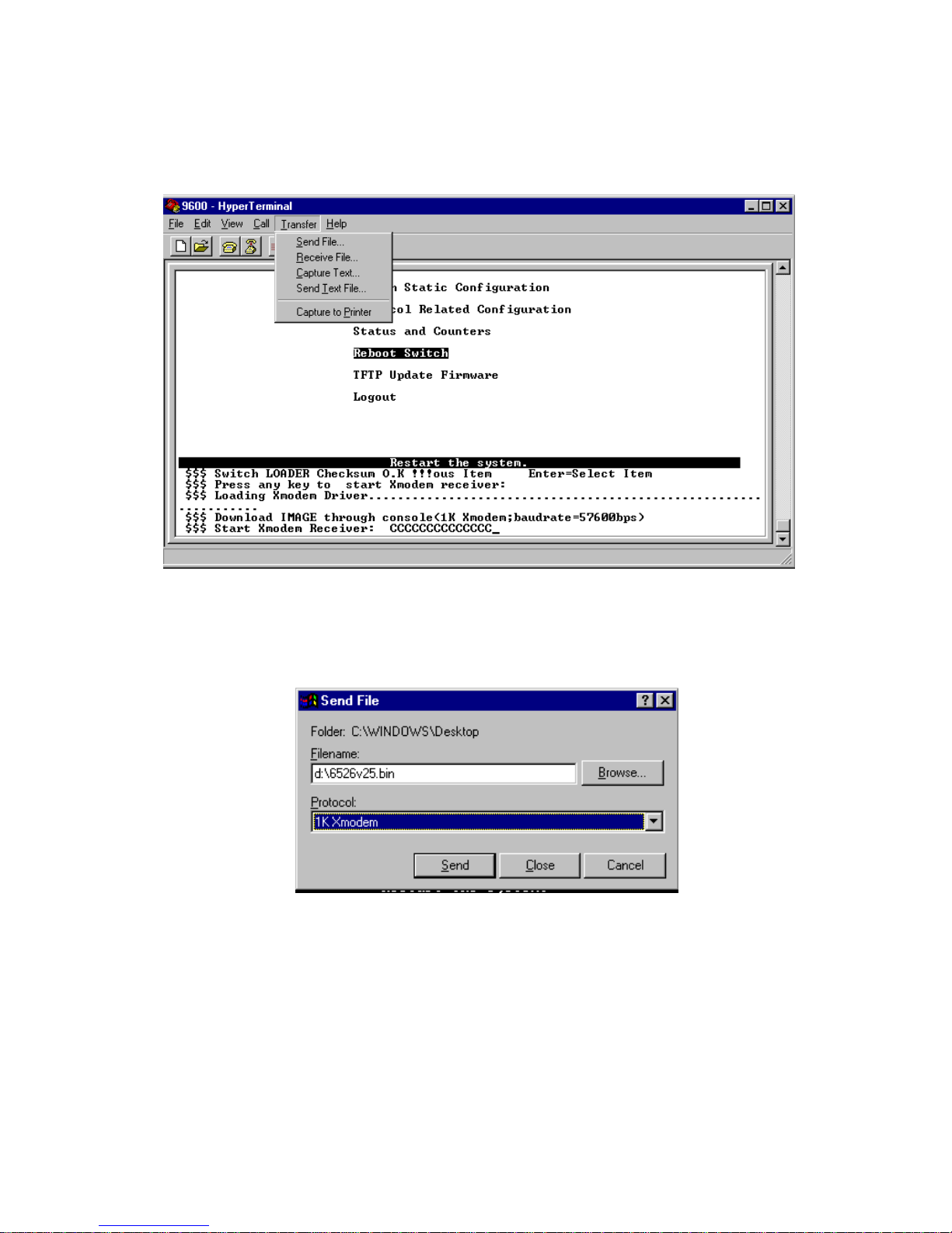
2. Press connected, you will see “CCCC…”displayed on console.
Then select Transfer Send File.
3. Select 1K Xmodem in the Protocol item, and give the place that image file folder. Press Send
button.
Page 53
- 53 -
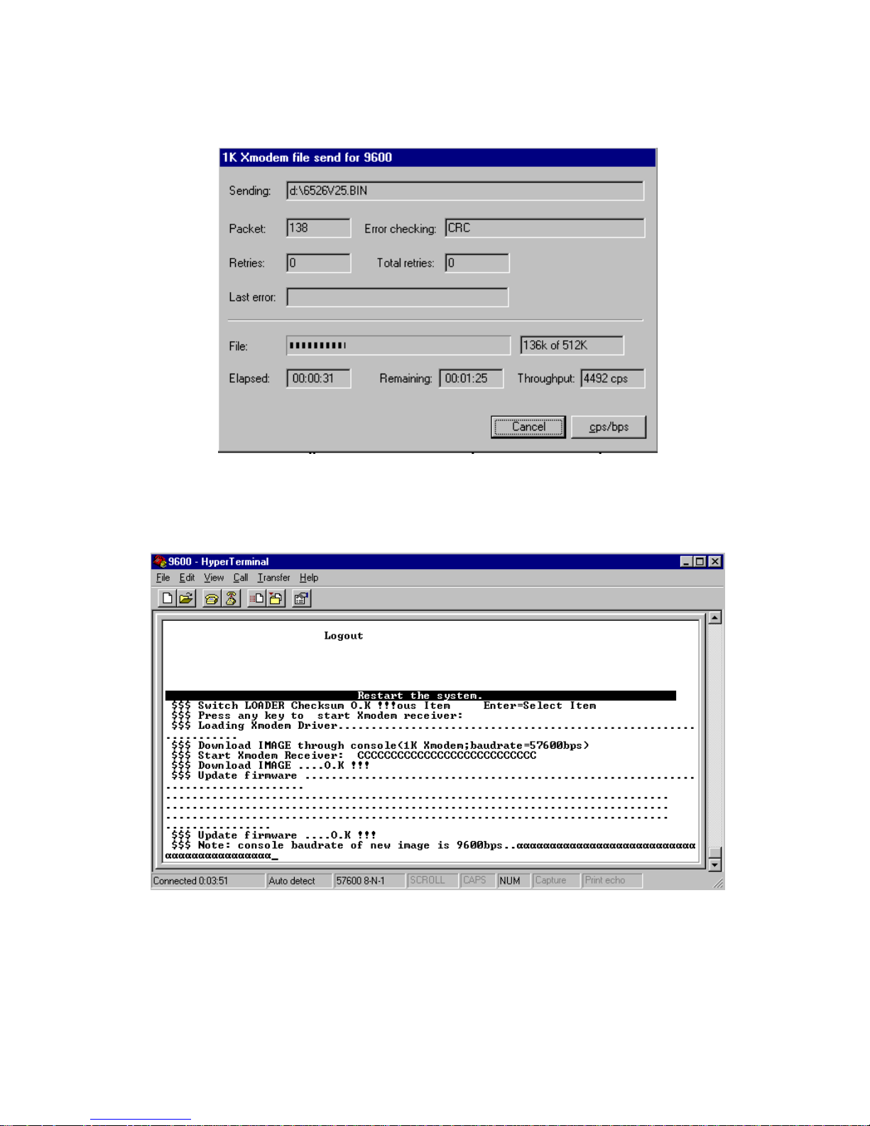
4. Start download image file.
5. Finish download image, the switch system will update firmware automatic. Update firmware ok,
the switch will reboot. Please change the boudrate to 9600bps.
Page 54

- 54 -
4. Out-of-band Terminal mode
management
1. FMX-24NZ switch also provide a serial interface to manage and monitor the switch, user
can follow the Console Port Information provide by web to use windows HyperTerminal
program to link the switch.
2. You can type user name and password to login. The default user name is “admin”; the
default password is “0000”.
Page 55
- 55 -
4.1 Main Menu
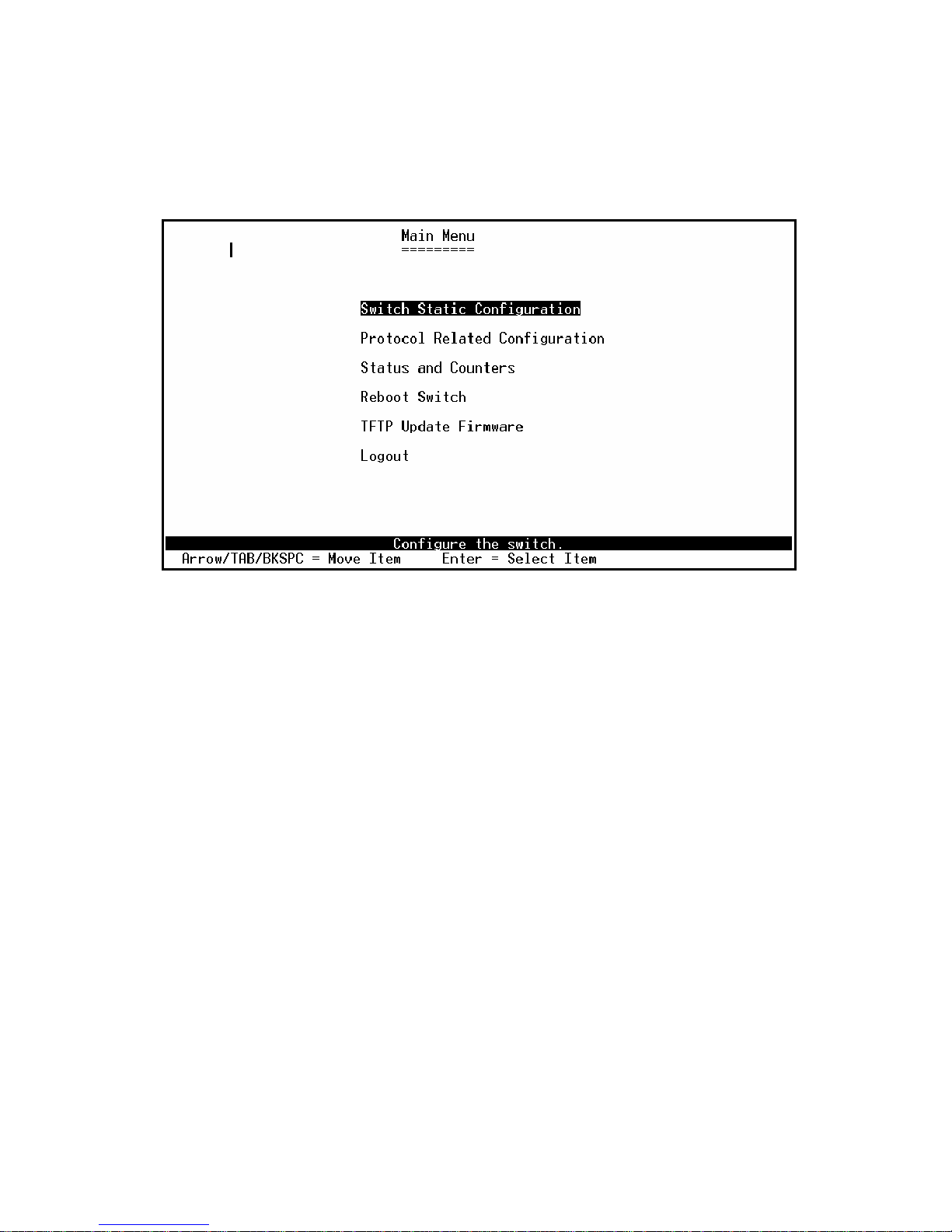
There are six items for selected as follows:
Switch Static Configuration: Configure the switch.
Protocol Related Configuration: Configure the protocol function.
Status and Counters: Show the status of the switch.
Reboot Switch: Restart the system or reset switch to default configuration.
TFTP Update Firmware: Use TFTP to download image.
Logout: Exit the menu line program.
<Control Key>
The control key as follow is provided for this mode operation:
Tab: Move the vernier to next item.
Backspace: Move the vernier to previous item.
Enter: Select item.
Space: Toggle selected item to next configure.
4.2 Switch Static Configuration
Page 56
- 56 -
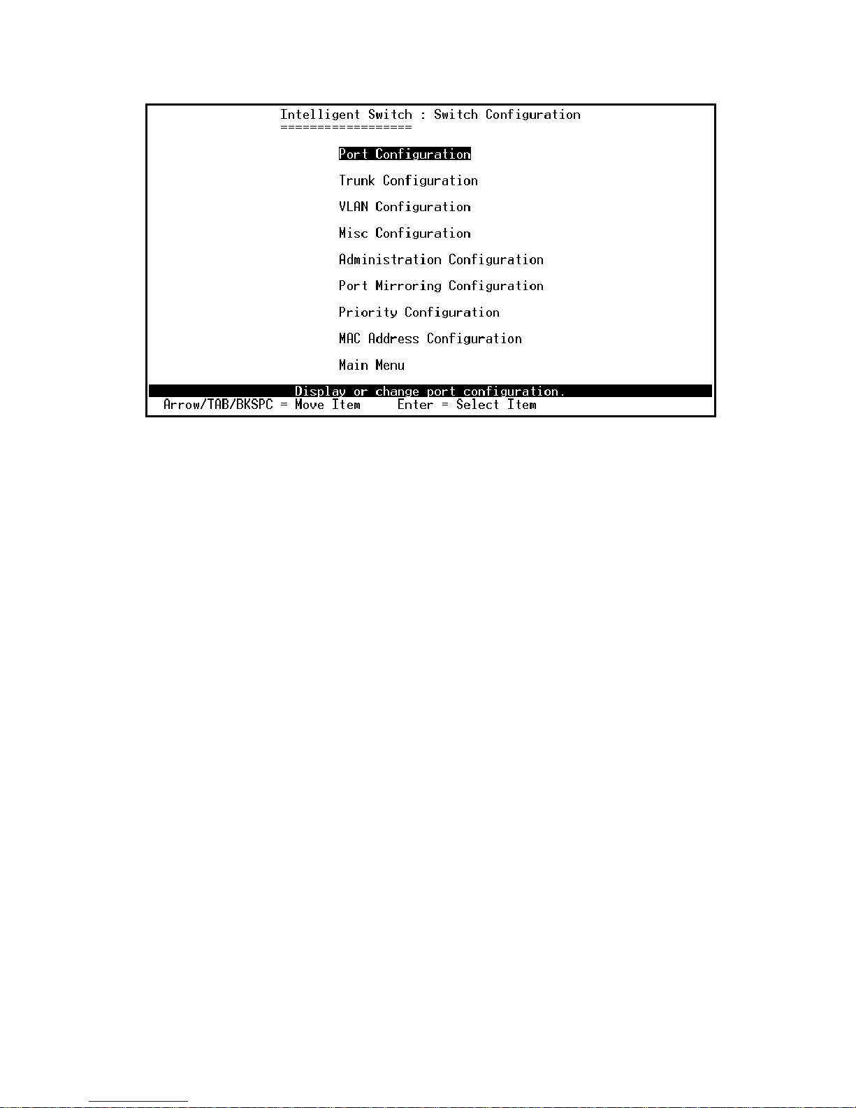
<Control Key>
You can press the key of Tab or Backspace to choose item, and press Enter key to select item
The action menu line as follow provided in later configure page.
Actions->
<Quit>: Exit the page of port configuration and return to previous menu.
<Edit>: Configure all items. Finished configure press
Ctrl+A: Back to action menu line.
<Save>: Save all configure value.
<Previous Page>: Return to previous page to configure.
<Next page>: Go to the next page to configure it.
Page 57
- 57 -
4.2.1. Port Configuration
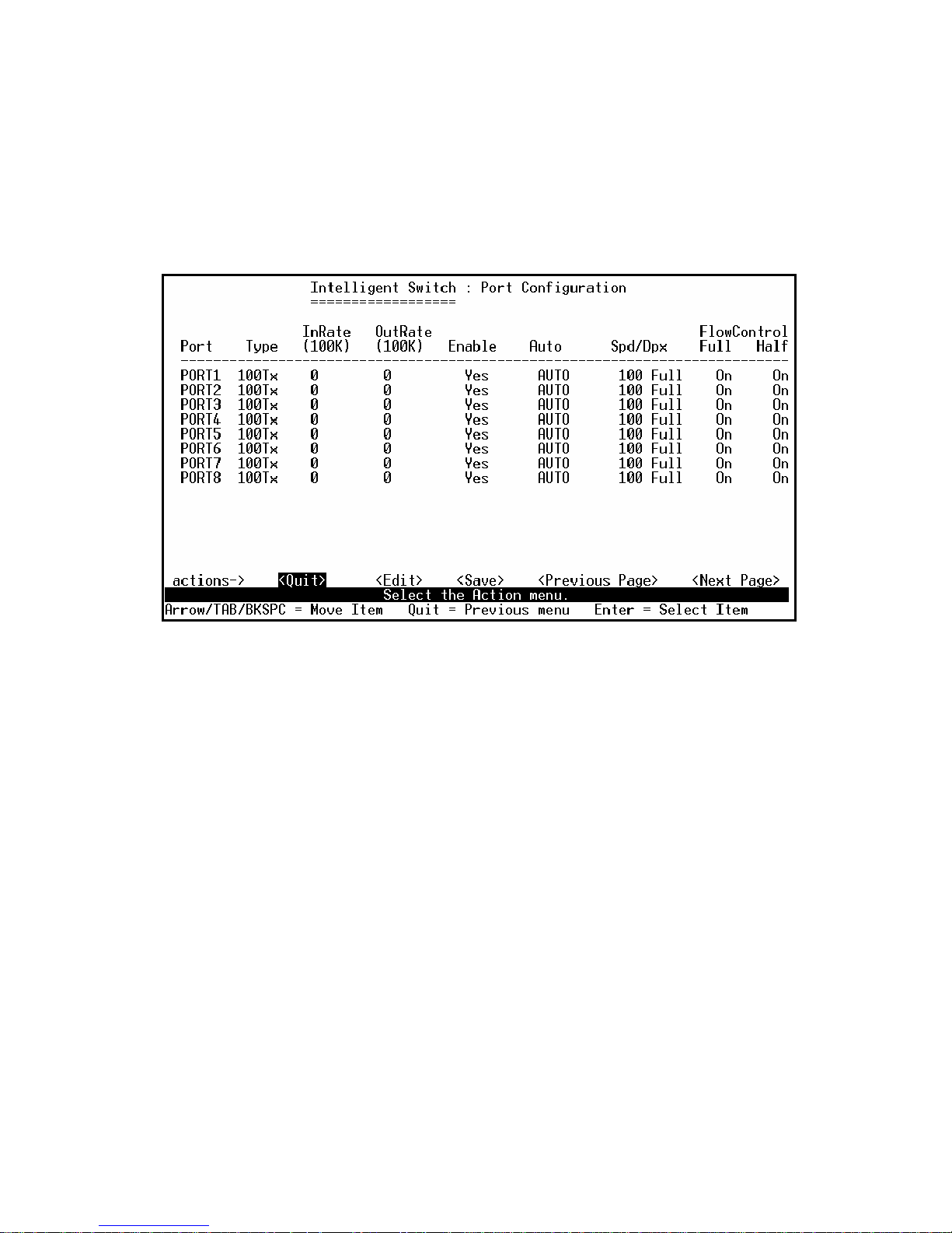
This page can change every port status.
Press Space key to change configures of per item.
1. InRate (100K/unit):
User can set input rate control, per unit is 100K. The valid range is 0~1000.
0: disable rate control.
1~1000: valid rate value.
2. OutRate (100K/unit):
User can set output rate control, per unit is 100K. The valid range is 0~1000.
0: disable rate control.
1~1000: valid rate value.
3. Enabled:
User can disable or enable this port control.
“Yes” that mean the port is enable.
“No” that mean the port is disable.
4. Auto:
User can set auto negotiation mode is “Auto”, “Nway_Force”, “Force” of per port.
5. Spd/Dpx:
User can set “100Mbps” or “10Mbps” speed on port 1~port 24,
Set “1000Mbps”, “100Mbps” or “10Mbps” speed on port25~port26 (depend on module card
mode), and set “full-duplex” or “half-duplex” mode.
Page 58

- 58 -
6. Flow Control:
Full: User can set full flow control function (pause) as enable or disable.
Half: User can set half flow control function (backpressure) as enable or disable.
NOTE:
1. Pressing <Save> only can save one page configuration.
2. If the static trunk groups exist, you can see it (ex: TRK1, TRK2…) after port 26, and you can configure all of the
items as above.
Page 59
- 59 -
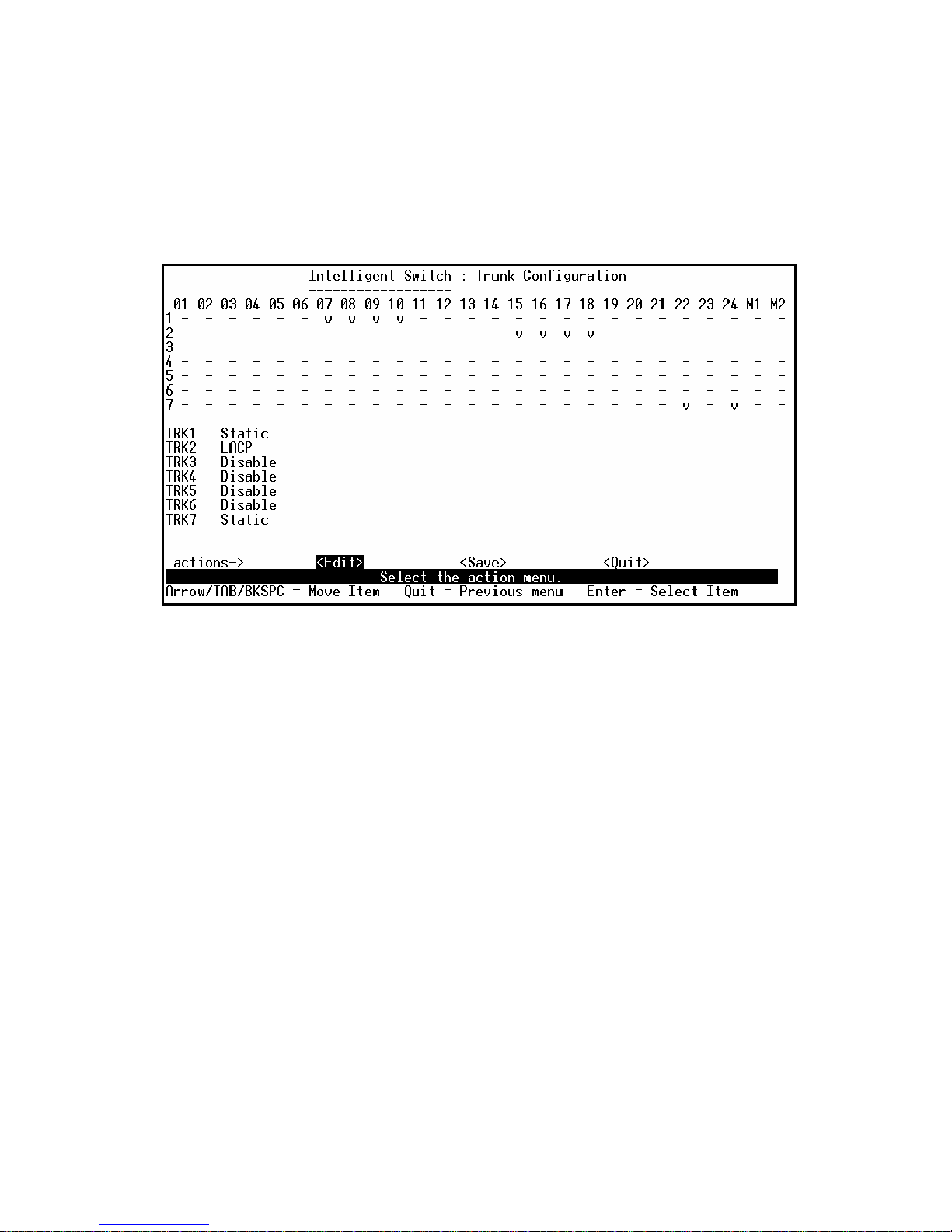
4.2.2. Trunk Configuration
This page can create max seven trunk groups. User can arbitrarily select up to four ports from port
1~port 26 to build a trunk group.
Actions->
1. Select <Edit> on actions menu
2. Press space key to configure the member port of trunk group. Besides, you have to set “Static” or
“LACP” for the corresponding trunk group of TRK1~TRK7 item.
“Static” – the normal trunk.
“LACP” – this trunk group have link aggregation control protocol.
3. Press Ctrl+A to go back action menu line
4. Select <Save> to save all configure value.
5. If the item of TRK1~TRK7 is set “Disable”, it’s mean the trunk group is deleted.
6. All ports in the same static trunk group will be treated as single port. So when you setting VLAN
members and Port configuration they will be toggled on or off simultaneously.
NOTE: If VLAN group exist, all of the members of static trunk group must be in same VLAN group.
Page 60
- 60 -
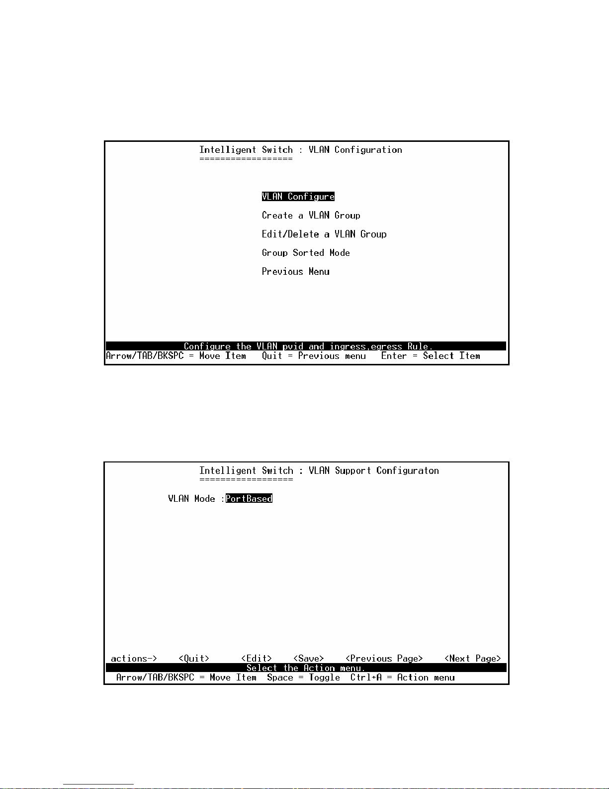
4.2.3. VLAN Configuration
4.2.3.1. VLAN Configure
This page can set VLAN mode to port-based VLAN or 802.1Q VLAN or disable VLAN function.
Page 61
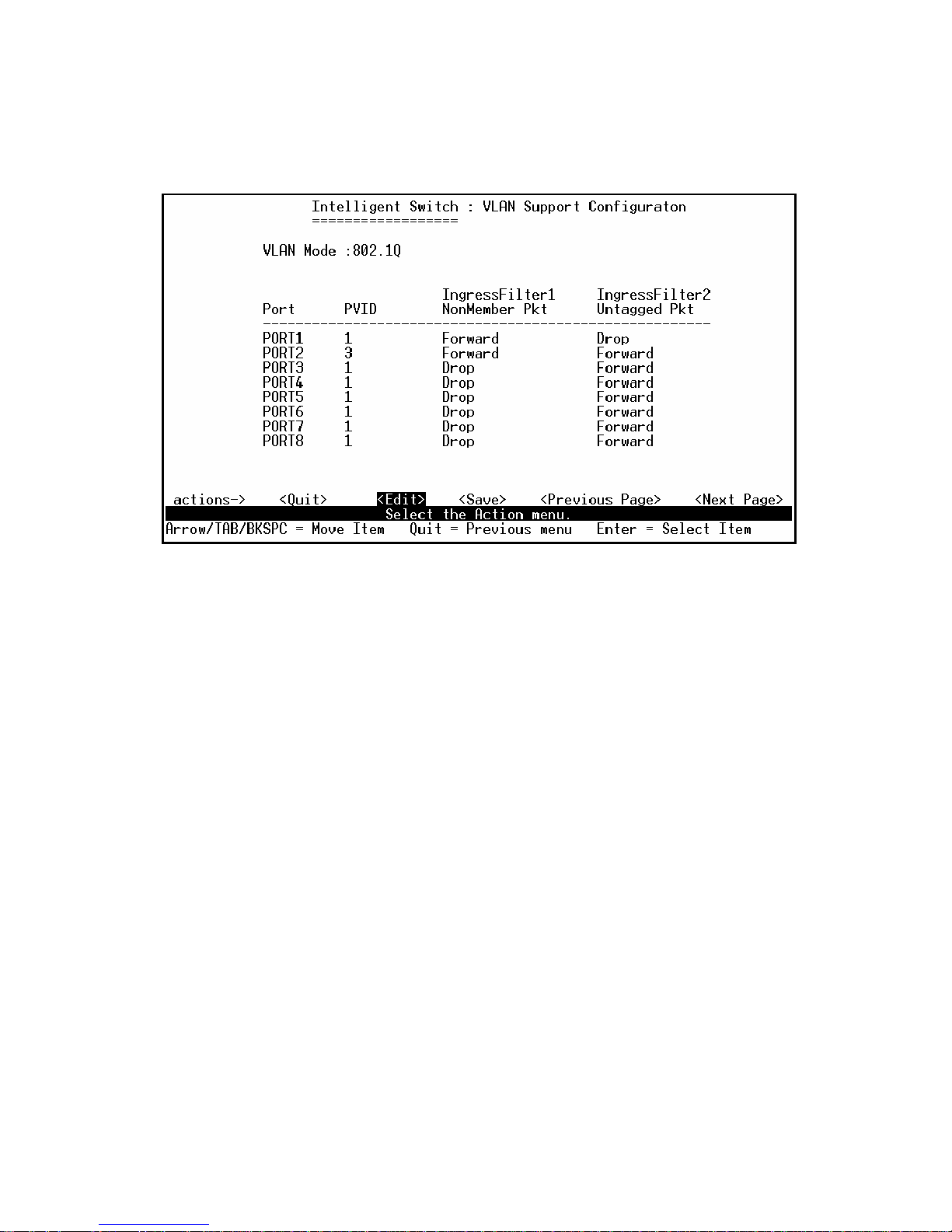
- 61 -
NOTE: Change the VLAN mode for every time, user have to restart the switch for valid value.
If set 802.1Q VLAN, you can set PVID, ingress filtering 1 and ingress filtering 2 in this page too.
Actions->
1. PVID (Port VID: 1~255): Type the PVID.
2. NonMember Drop:
It matches that Ingress Filtering Rule 1 on web.
Forwarding only packets with VID matching this port’s configured VID.
Press Space key to choose “forward” or “drop” the frame that VID not matching this port’s
configured VID.
3. UnTagged Drop:
It matches that Ingress Filtering Rule 2 on web.
Drop untagged frame.
Press Space key to choose “drop” or “forward” the untagged frame.
Page 62
- 62 -
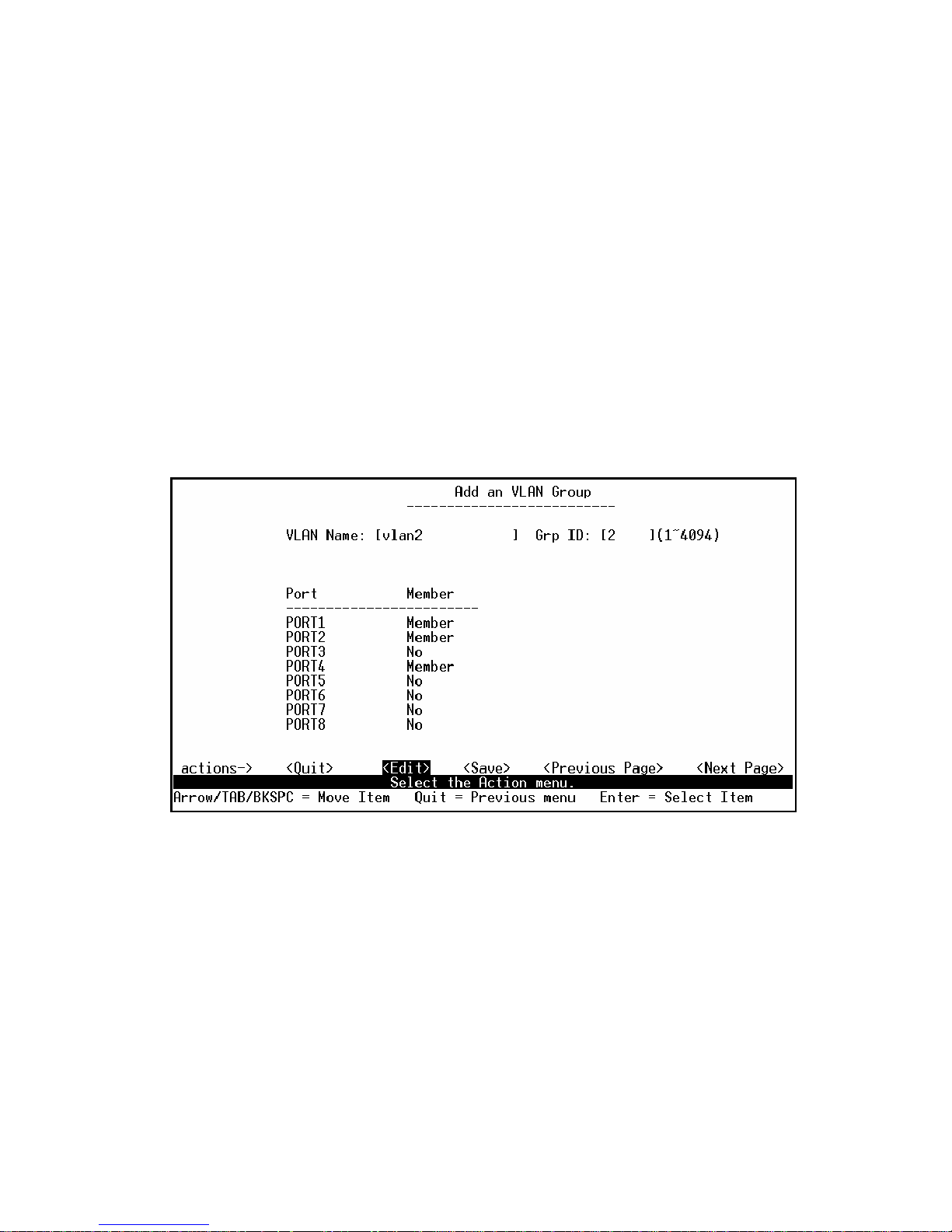
4.2.3.2. Create a VLAN Group
◆ Create Port-Based VLAN
Create a port-based VLAN and add member/nonmember ports to it.
1. Select <Edit>.
2. VLAN Name: Type a name for the new VLAN.
3. Grp ID: Type the VLAN group ID. The group ID rang is 1~4094.
4. Member: Press <Space> key to choose VLAN member. There are two types to selected:
a. Member: the port is member port.
b. No: the port is NOT member port.
5. Press Ctrl+A go back action menu line.
6. Select <Save> to save all configure value.
NOTE: If the trunk groups exist, you can see it (ex: TRK1, TRK2…) after port26, and you can
configure it is the member of the VLAN or not.
Page 63
- 63 -
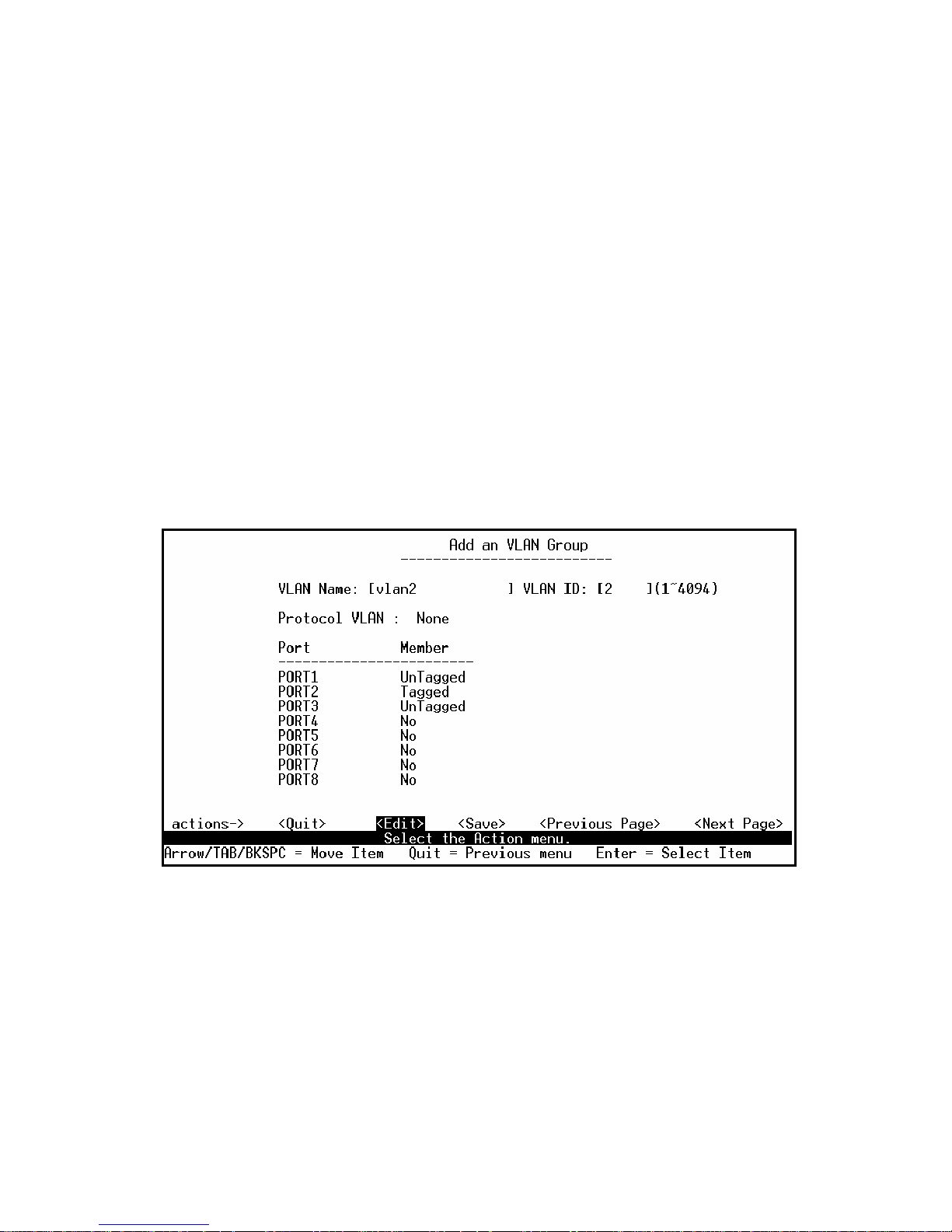
Create 802.1Q VLAN
Create an 802.1Q VLAN and add tagged /untagged member ports to it.
1. Select <Edit>.
2. VLAN Name: Type a name for the new VLAN.
3. VLAN ID: Type a VID (between 1~4094). The default is 1. There are 256 VLAN groups to
provided configure.
4. Protocol VLAN: Press Space key to choose protocols type.
5. Member: Press Space key to choose VLAN member. There are three types to selected:
a. UnTagged:This port is the member port of this VLAN group and outgoing frames are NO
VLAN-Tagged frames.
b. Tagged:This port is the member port of this VLAN group and outgoing frames are
VLAN-Tagged frames.
c. NO:The port is NOT member of this VLAN group.
6. Press Ctrl+A go back action menu line.
7. Select <Save> to save all configure value.
NOTE: If the trunk groups exist, you can see it (ex: TRK1, TRK2…) after port 26, and you can
configure it is the member of the VLAN or not.
Page 64
- 64 -
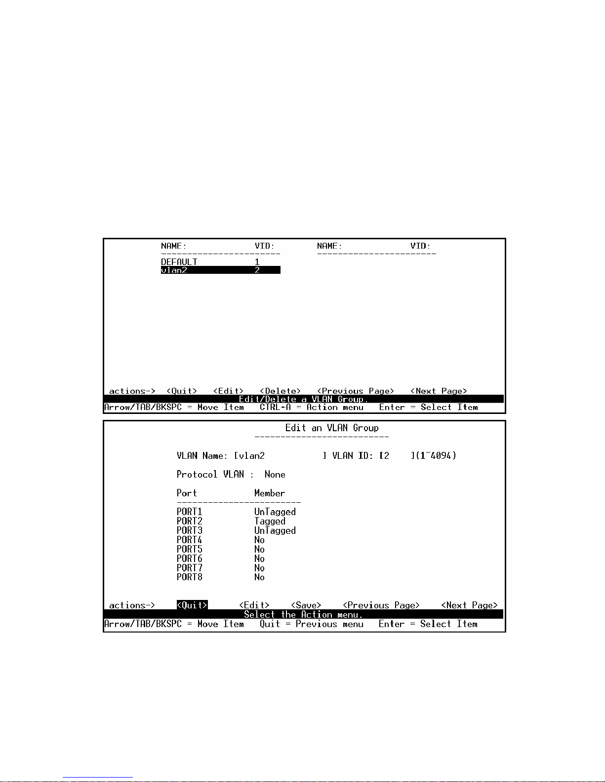
4.2.3.3. Edit / Delete a VLAN Group
In this page, user can edit or delete a VLAN group.
1. Press <Edit> or <Delete> item.
2. Choose the VLAN group that you want to edit or delete and then press enter.
3. User can modify the protocol VLAN item and the member ports are tagged or un-tagged and
remove some member ports from this VLAN group.
4. After edit VLAN, press <Save> key to save all configures value.
NOTE:
1. When pressing <Enter> once will complete deletion on delete mode.
2. The VLAN Name and VLAN ID cannot modify.
3. The default VLAN can’t be deleting.
Page 65
- 65 -
4.2.3.4. Groups Sorted Mode
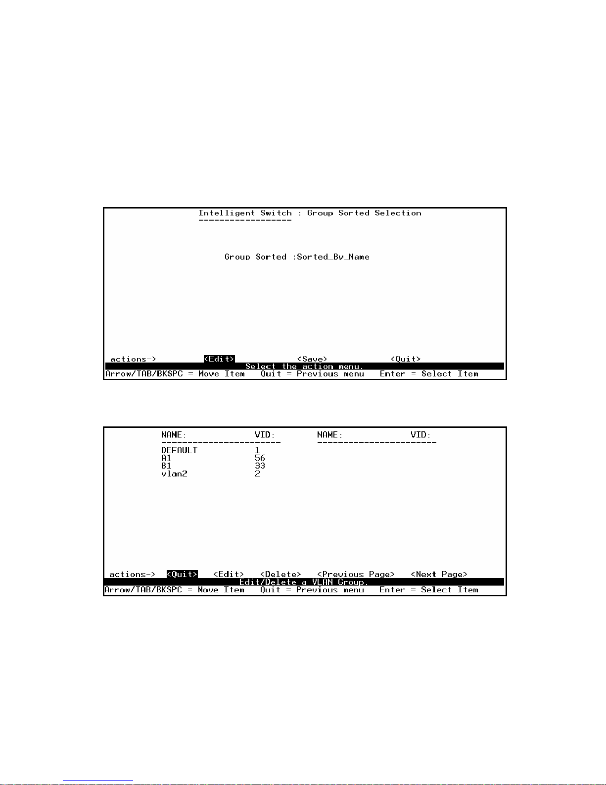
In this page, user can select VLAN groups sorted mode:
(1) sorted by name
(2) Sorted by VID.
The Edit/Delete a VLAN group page will display the result.
In the Edit/Delete a VLAN Group page, the result of sorted by name.
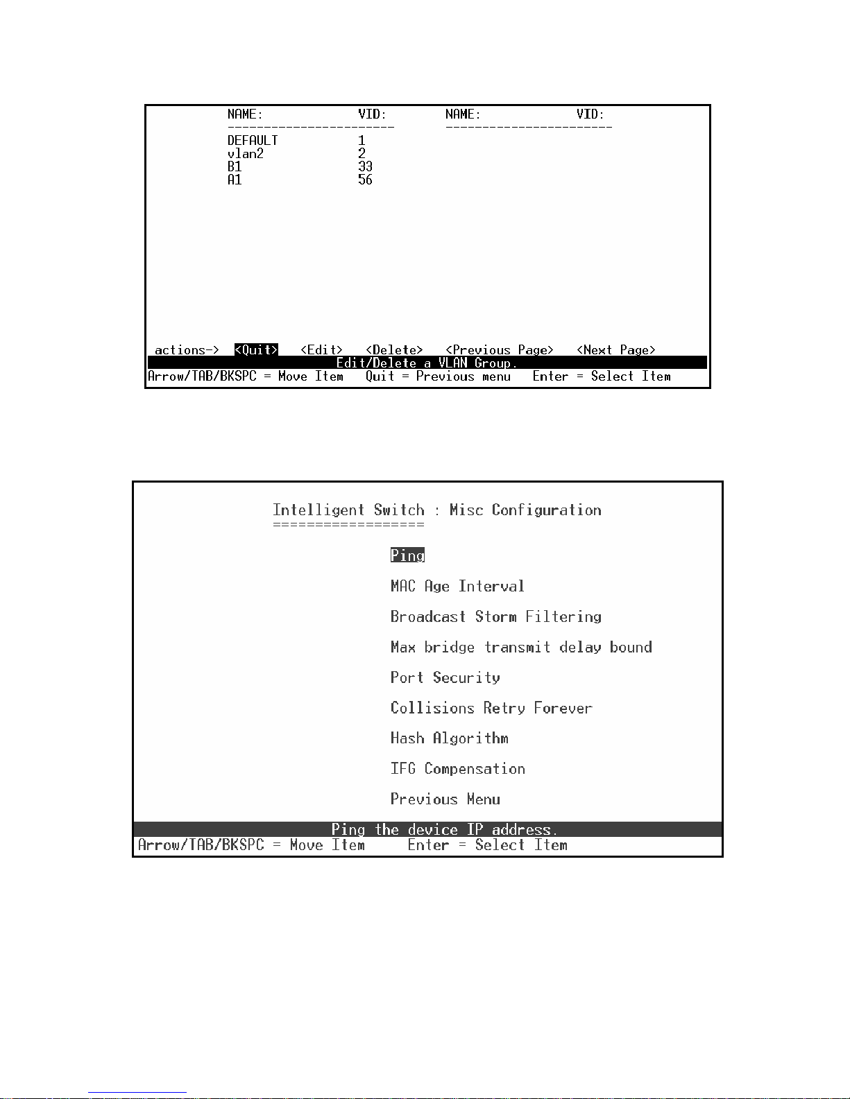
In the Edit/Delete a VLAN Group page, the result of sorted by VID.
Page 66
- 66 -
4.2.4. Misc Configuration
Page 67
- 67 -
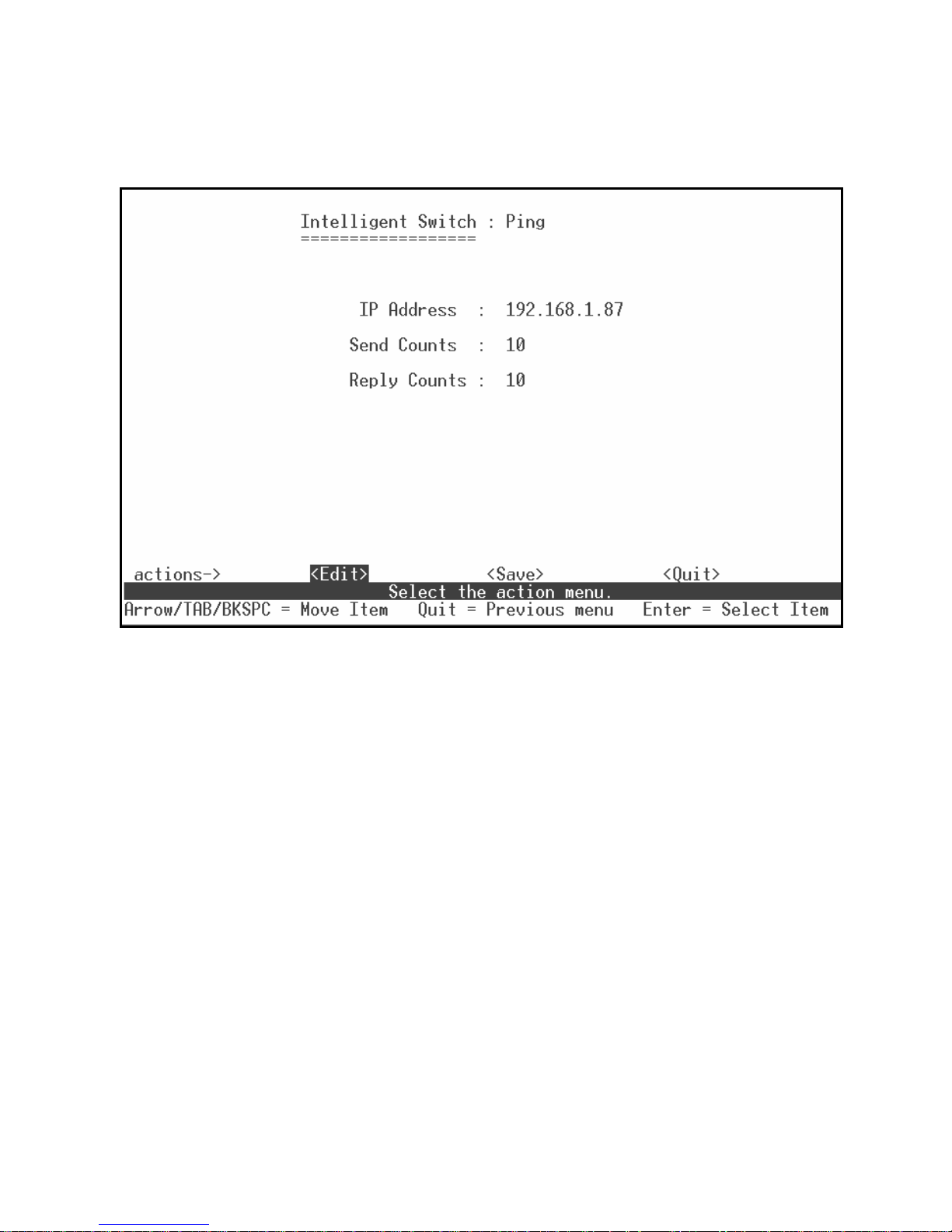
4.2.4.1. Ping
Type the Host IP and the counts for pinging, then back to action menu and press “Save”. “Reply
Counts” will display the result of pinging.
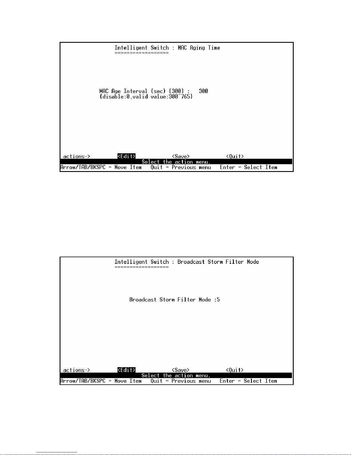
4.2.4.2. MAC Age Interval
Type the number of seconds that an inactive MAC address remains in the switch’s address table.
The valid range is 300~765 seconds. Default is 300 seconds.
Page 68
- 68 -
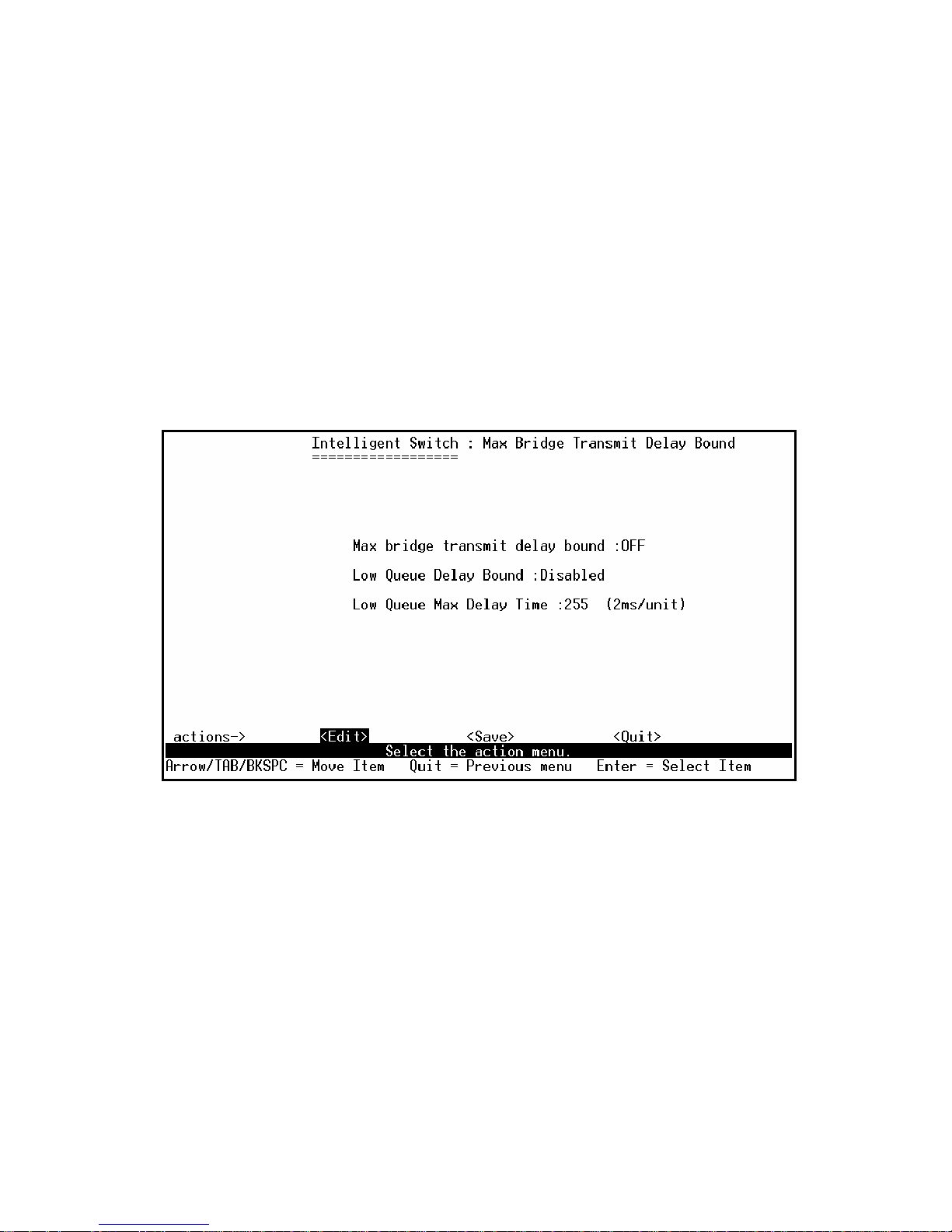
4.2.4.3. Broadcast Storm Filtering
This page is configuring broadcast storm control.
1. Press <Edit> to configure the broadcast storm filter mode.
2. Press Space key to choose the threshold value.
The valid threshold value is 5%, 10%, 15%, 20%, 25% and NO. Default is 5%.
Page 69
- 69 -
4.2.4.4. Max bridge transmit delay bound
1. Max bridge transmit delay bound: Limit the packets queuing time in switch. If enabled, the
packets queued exceed will be drop. Press Space key to set the time. Those valid values are 1sec,
2sec, and 4sec and off. Default is off.
2. Low Queue Delay Bound: Limit the low priority packets queuing time in switch. If enabled, the
low priority packet stays in switch exceed Low Queue Max Delay Time, it will be sent. Press
Space key to enable or disable this function. Default is disable.
3. Low Queue Max Delay Time: To set the time that low priority packets queuing in switch. The
valid range is 1~255ms. Default Max Delay Time is 255ms.
NOTE: Make sure “Max bridge transit delay bound control” is enabled before enabling Low Queue
Delay Bound, because Low Queue Delay Bound must be work under “Max bridge transit
delay bound control” is enabled situation.
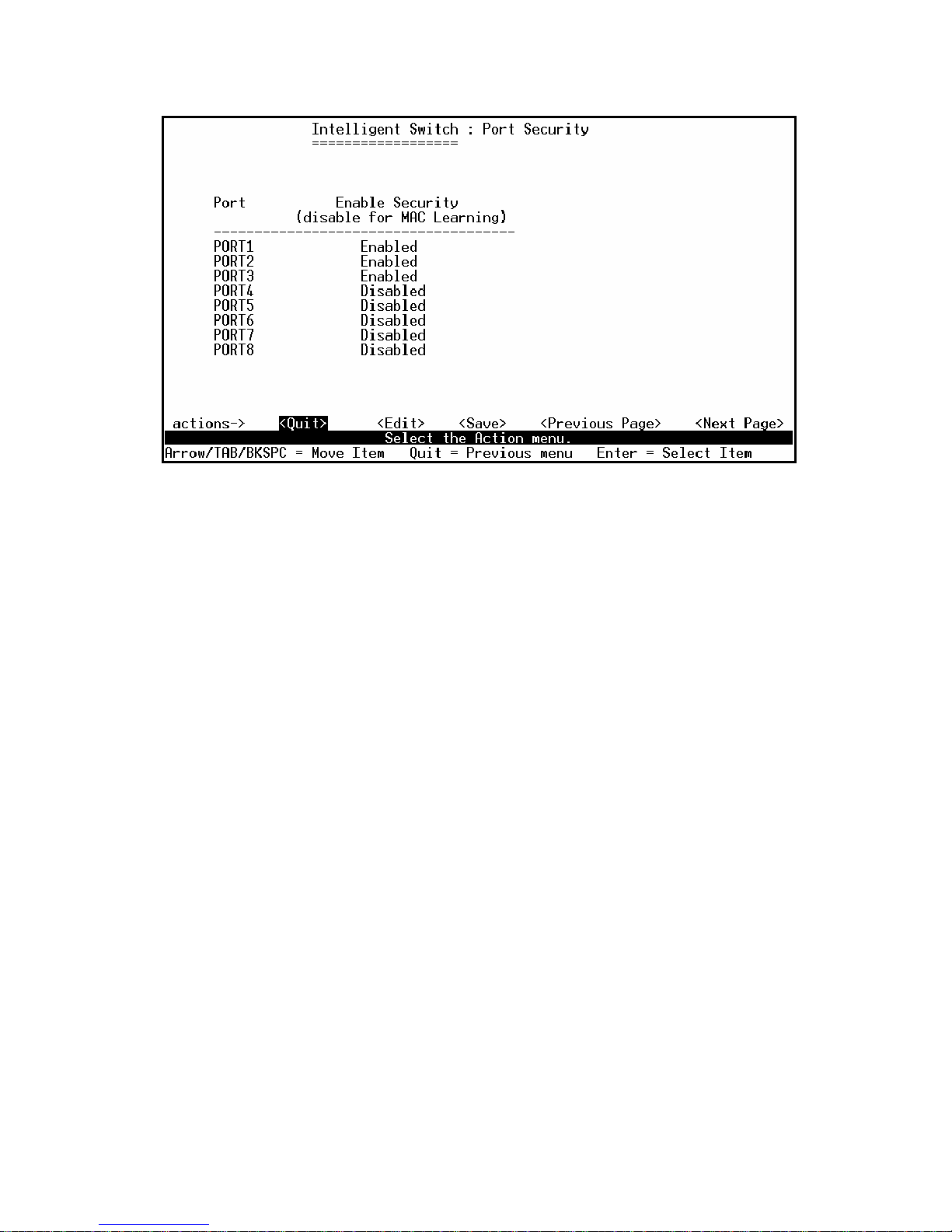
4.2.4.5. Port Security
A port in security mode will be “locked” without permission of address learning. Only the incoming
packets with SMAC already existing in the address table can be forwarded normally. User can disable
the port from learning any new MAC addresses, then use the static MAC addresses screen to define a
list of MAC addresses that can use the secure port.
Page 70
- 70 -
Actions->
1. Select <Edit>.
2. Press Space key to choose enable / disable item.
3. Press Ctrl+A to go back action menu line.
4. Select <Save> to save all configure value.
5. You can press <Next Page> to configure port9 ~ port26, press <Previous Page> return to last
page.
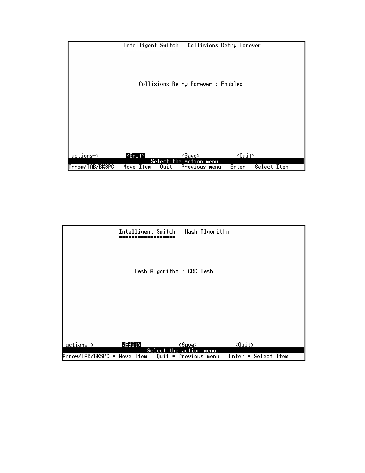
4.2.4.5. Collisions Retry Forever
Collisions Retry Forever: Disable – In half duplex, if happen collision will retry 48 times and then
drop frame.
Enable – In half duplex, if happen collision will retry forever (Default).
Page 71
- 71 -
4.2.4.6. Hash Algorithm
Select CRC-Hash(default) or DirectMap for Hash algorithm.
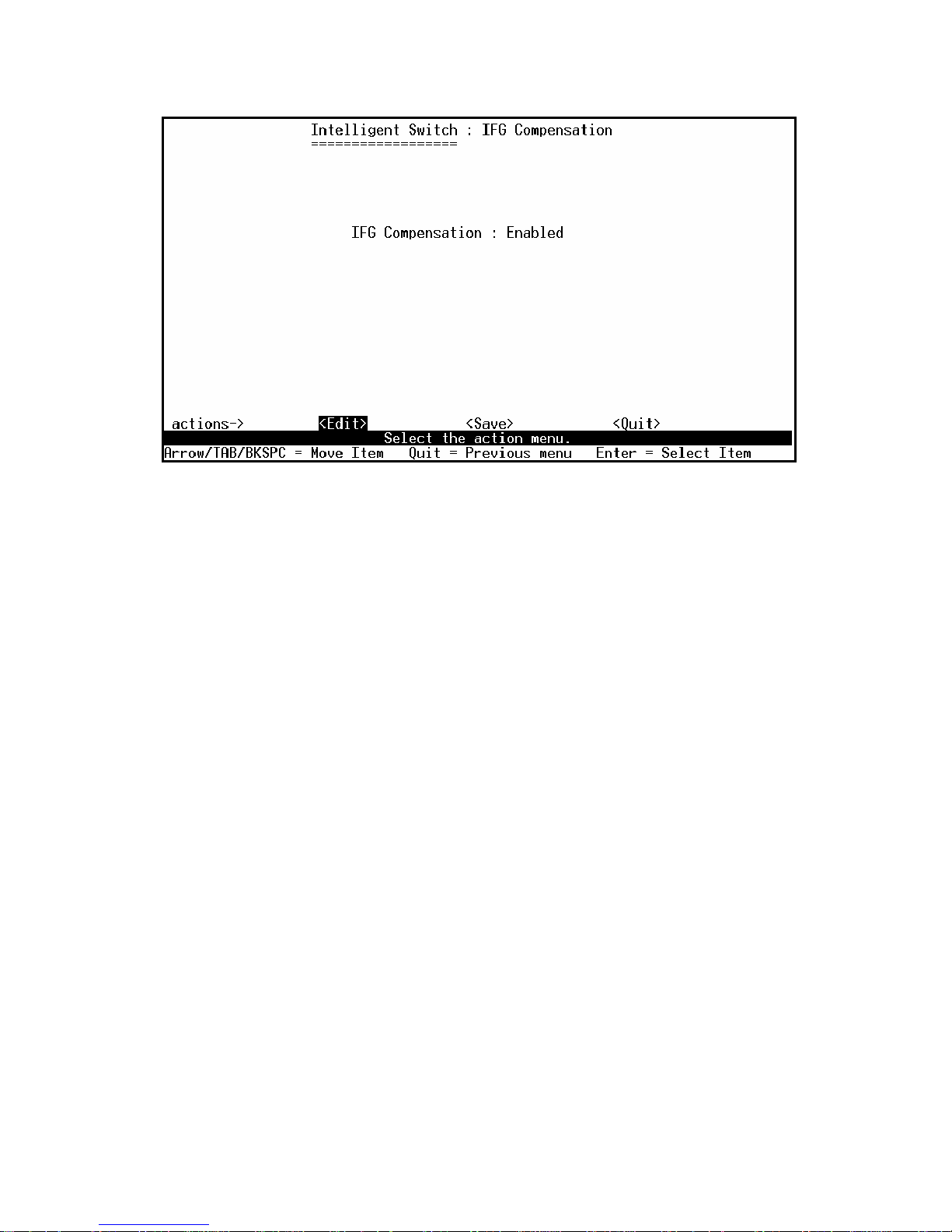
4.2.4.7. IFG Compensation
Enable or disable the inter-frame gap (IFG) compensation function.
Page 72
- 72 -
Page 73
- 73 -
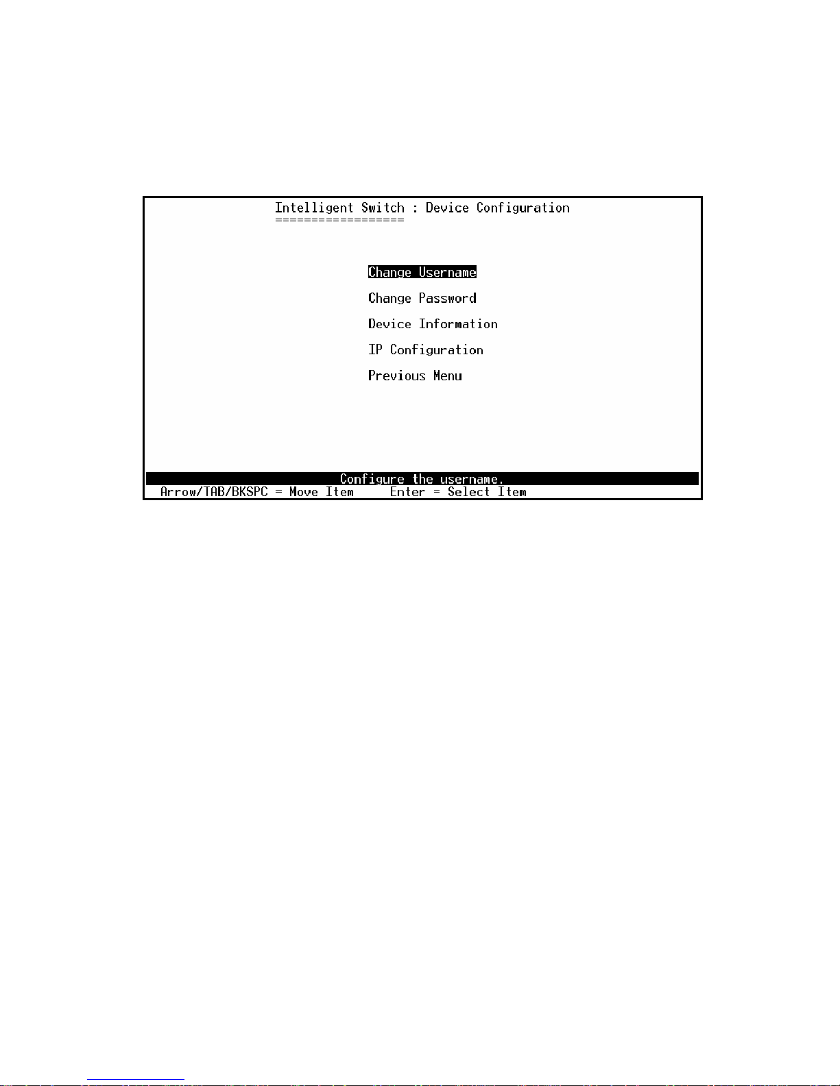
4.2.5. Administration Configuration
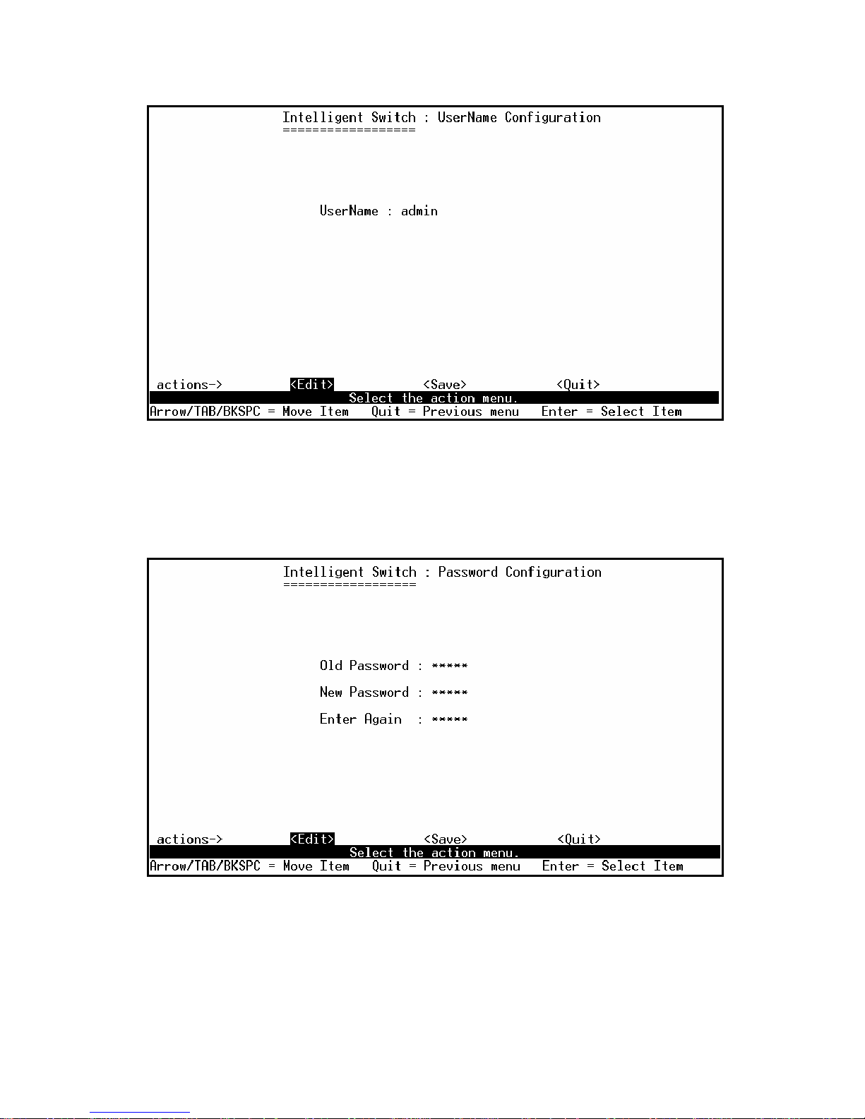
4.2.5.1. Change Username
Use this page; user can change web management user name.
Type the new user name, and then press <Save> item.
Page 74
- 74 -
4.2.5.2. Change Password
Use this page; user can change web management login password.
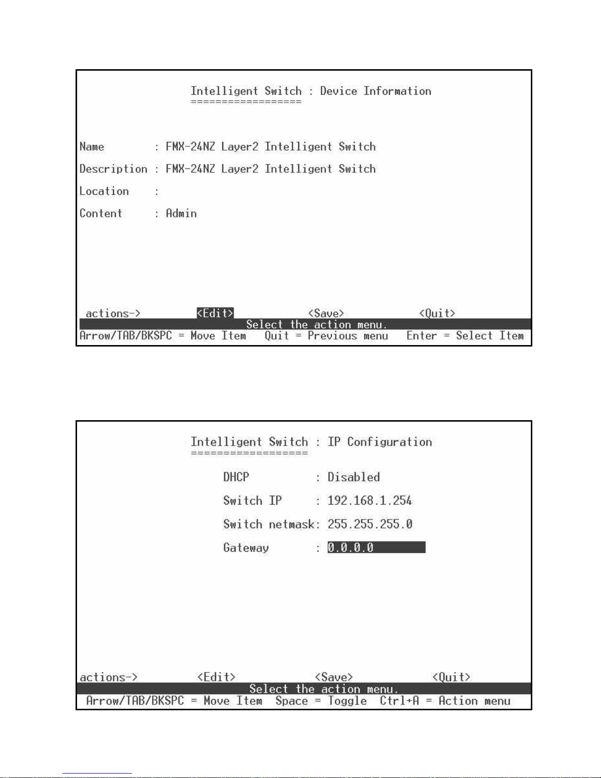
4.2.5.3. Device Information
This page is provided to the user to configure the device information.
Page 75
- 75 -
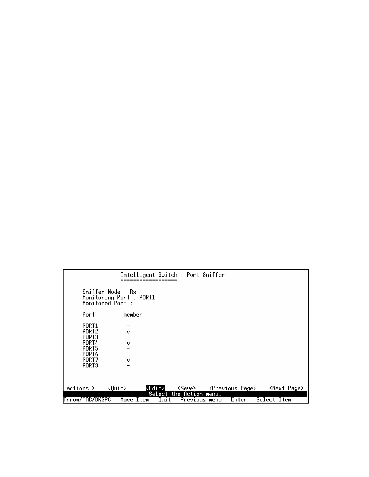
4.2.5.4. IP Configuration
User can configure the IP setting and fill in the new value.
Page 76
- 76 -
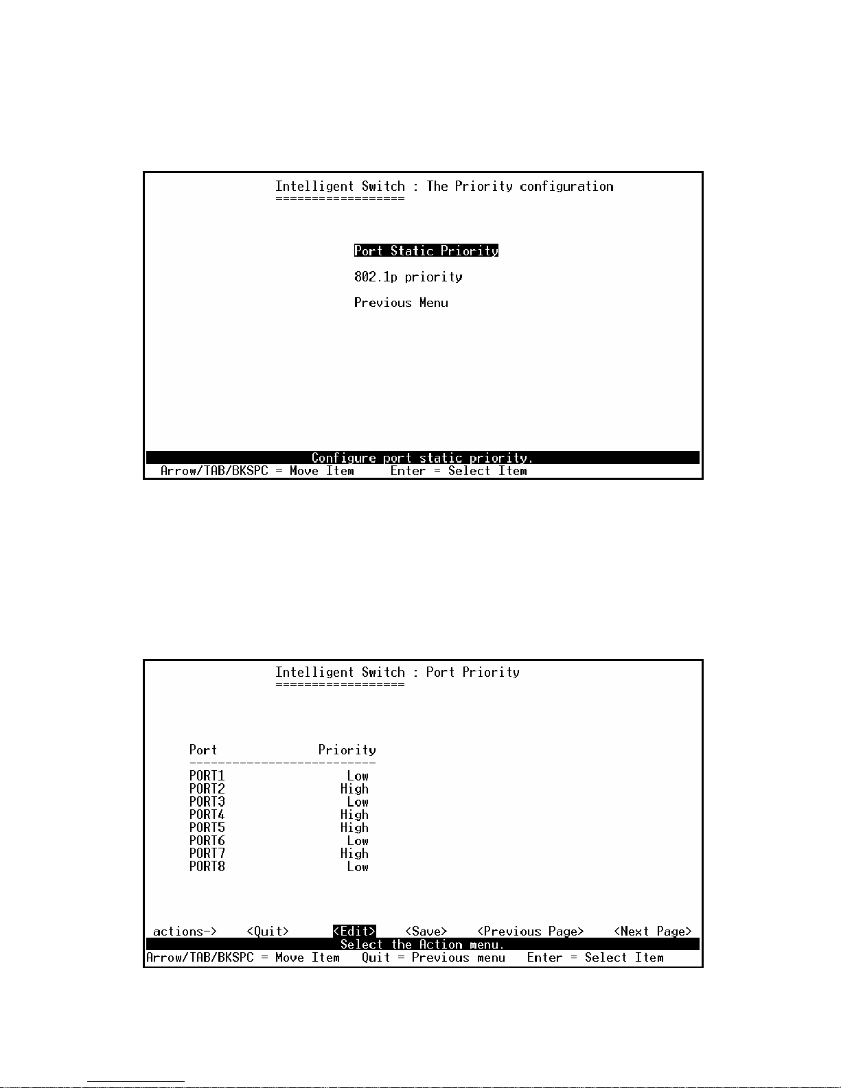
4.2.6. Port Mirror Configuration
The port mirroring is a method for monitor traffic in switched networks. Traffic through ports can be
monitored by one specific port. That is traffic goes in or out monitored ports will be duplicated into
monitoring port.
Actions->
Press Space key to change configure of per item.
1. Select <Edit>.
2. Sniffer Mode: Press Space key to set sniffer mode Disable、Rx、Tx or Both.
3. Monitoring Port: It means sniffer port can be used to see all monitors port traffic. Press Space
key to choose it.
4. Monitored Port: The ports you want to monitor. All monitor port traffic will be copied to sniffer
port. You can select max 25 monitor ports in the switch. User can choose which port to monitor in
only one sniffer mode. Press Space key to choose member port, “V” – is the member, “—“ – not
the member.
5. Press Ctrl+A go back action menu line
6. Select <Save> to save all configure value.
7. On the action menu line you can press <Next Page> to configure port9 ~ port26, press <Previous
Page> return to last page.
NOTE: Only has one sniffer mode in switch at the same time.
Page 77
- 77 -
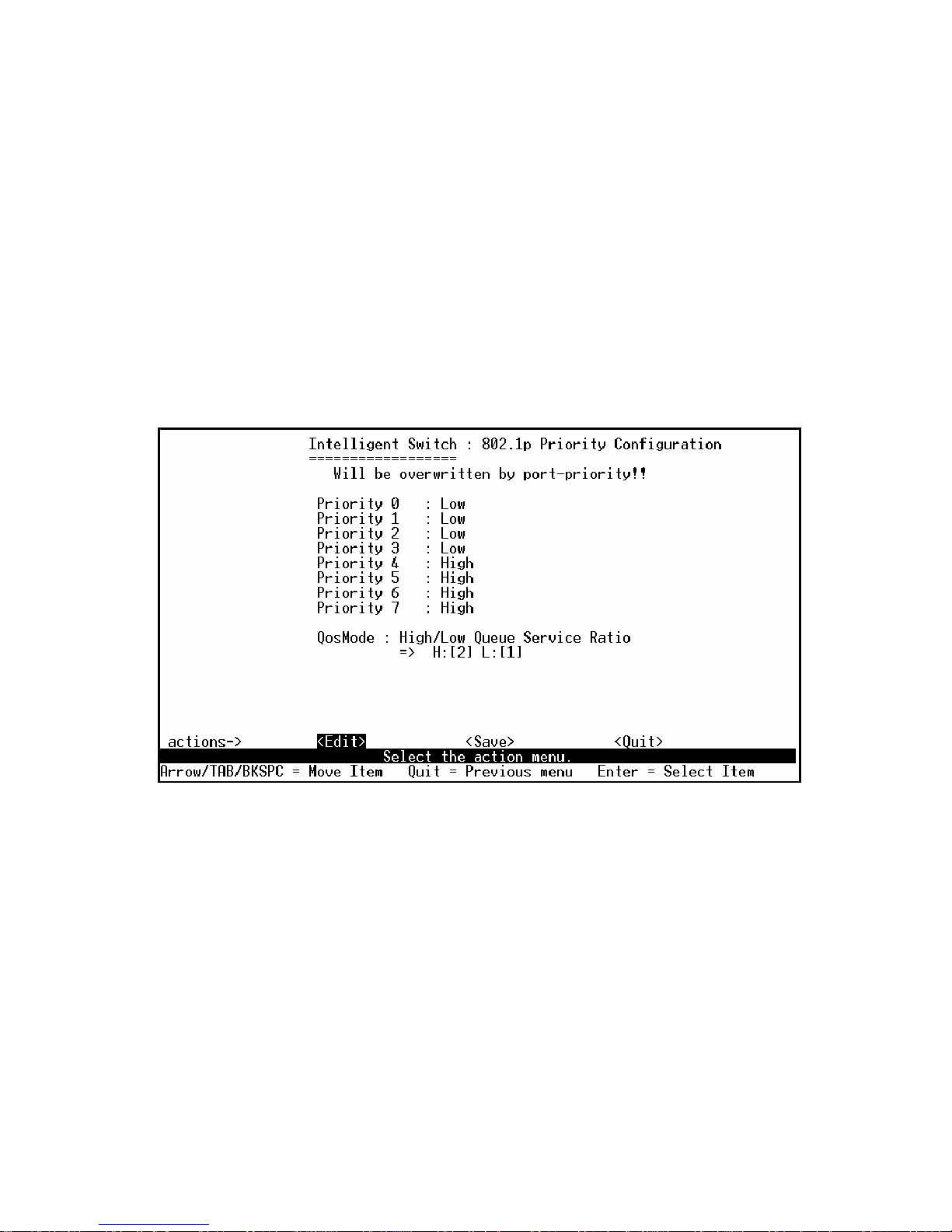
4.2.7. Priority Configuration
4.2.7.1. Port Static Priority
This static priority based on port, if you set the port is high priority, income frame from this port
always high priority frame.
Page 78
- 78 -
4.2.7.2. 802.1p Priority Configuration
There are 0~7-priority level can map to high or low queue.
Actions->
1. Select <Edit>.
2. Press Space key to select the priority level mapping to high or low queue.
3. High/Low Queue Service Ration H:L: User can select the ratio of high priority packets and low
priority packets.
4. Press Ctrl+A go back action menu line.
5. Select <Save> to save all configure value.
Page 79
- 79 -
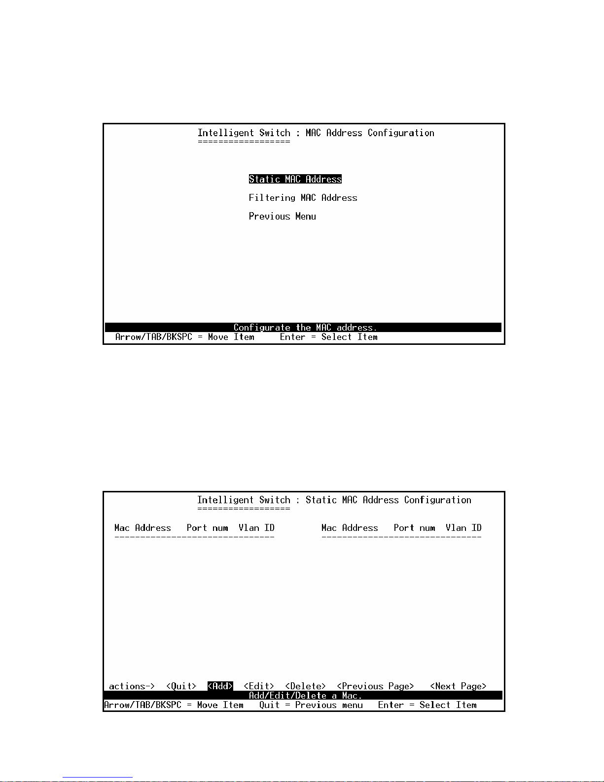
4.2.8. MAC Address Configuration
4.2.8.1. Static MAC Address
When you add a static MAC address, it remains in the switch's address table, regardless of whether
the device is physically connected to the switch. This saves the switch from having to re-learn a
device's MAC address when the disconnected or powered-off device is active on the network again.
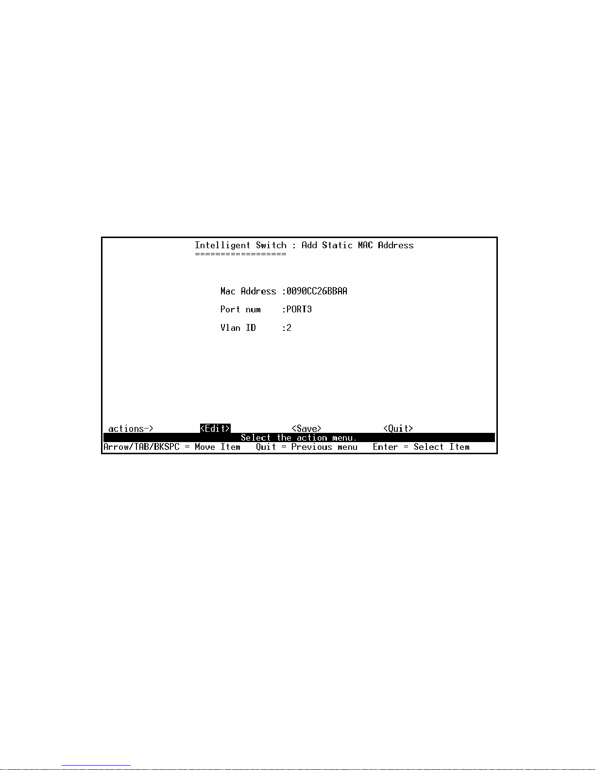
In this page user can add / modify / delete a static MAC address.
Page 80
- 80 -
●
Add static MAC address
Actions->
1. Press <Add> --> <Edit> key to add static MAC address.
2. MAC Address: Enter the MAC address to and from which the port should permanently forward
traffic, regardless of the device’s network activity.
3. Port num: press <Space> key to select the port number.
4. Vlan ID: If tag-based (802.1Q) VLAN are set up on the switch, static addresses are associated
with individual VLANs. Type the VID to associate with the MAC address.
5. Press Ctrl+A to go back action menu line.
6. Then select <Save> to save all configure value.
●
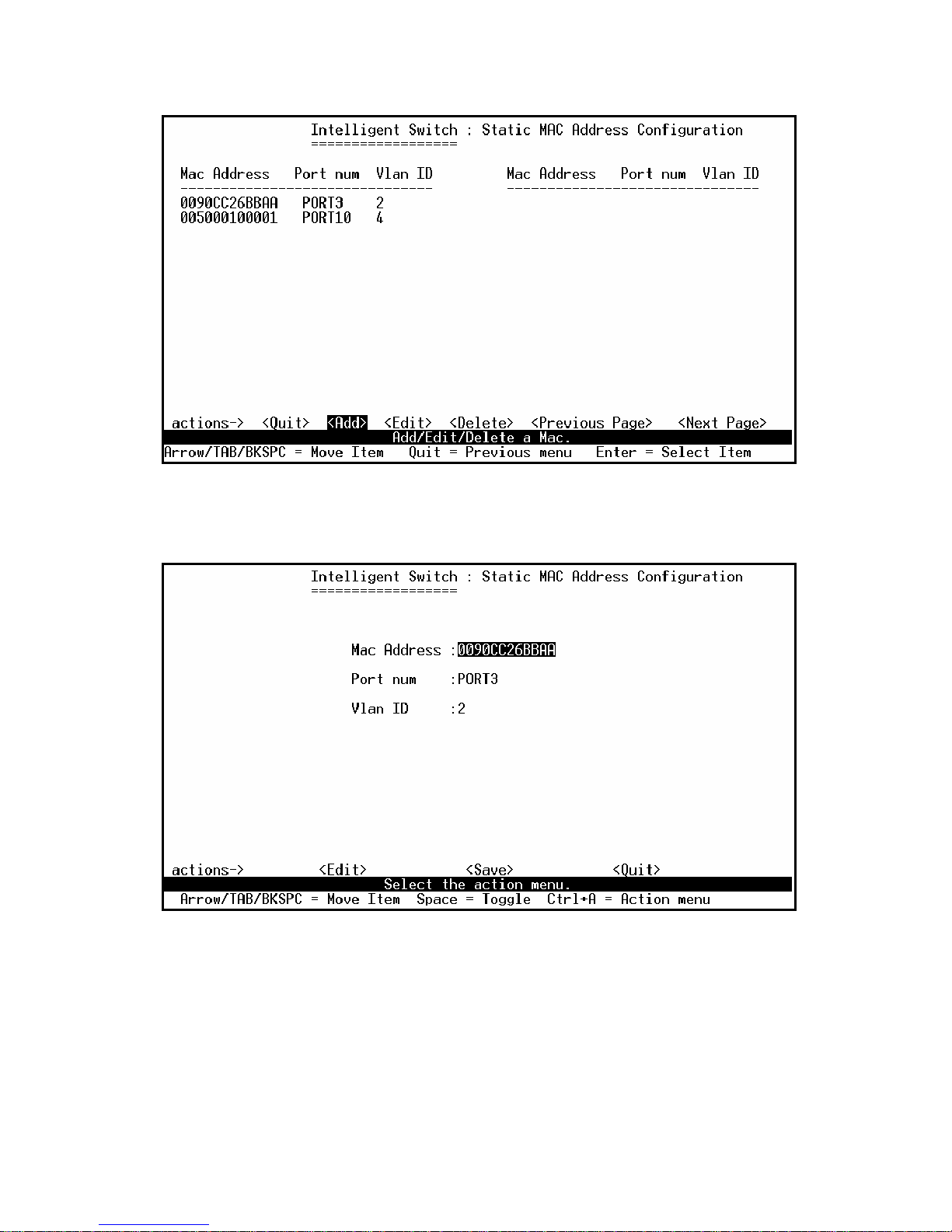
Edit static MAC address
Actions->
1. Press <Edit> key.
2. Choose the MAC address that you want to modify and then press enter.
Page 81
- 81 -
3. Press <Edit> key to modify all the items.
4. Press Ctrl +A to go back action menu line, and then select <Save> to save all configure value.
●
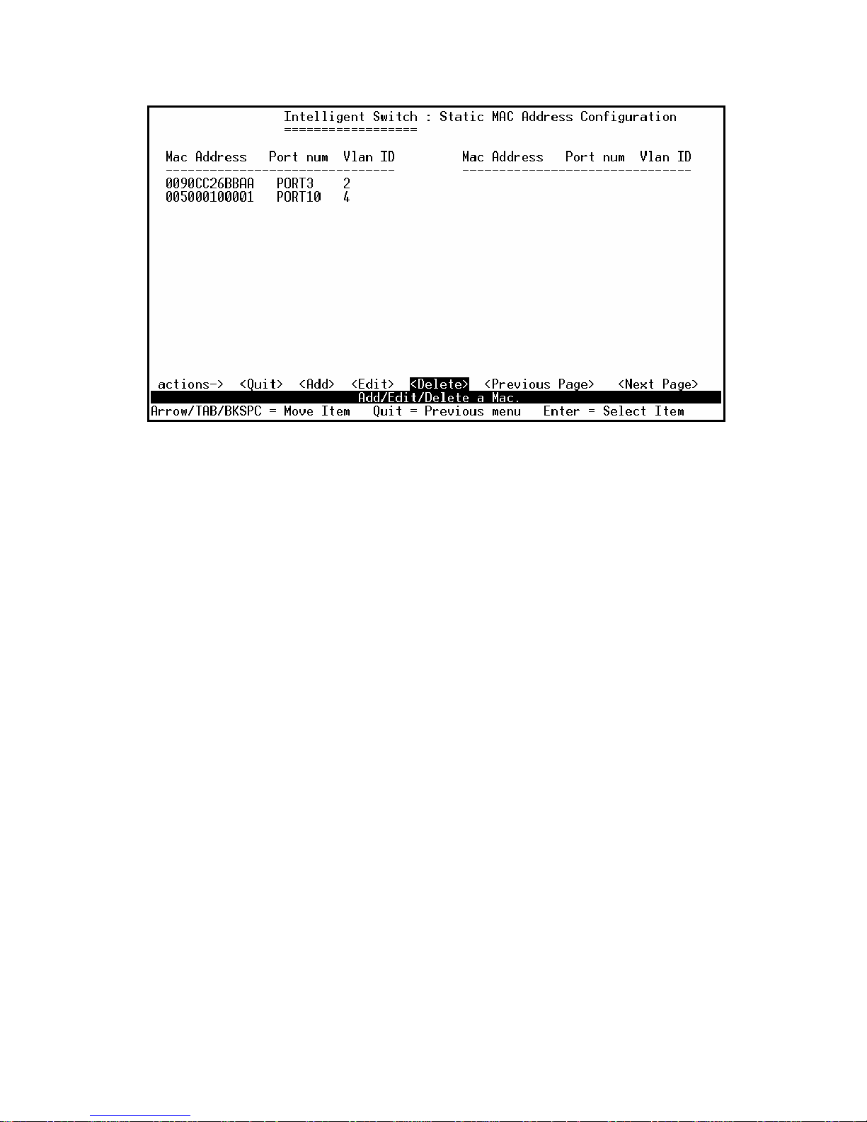
Delete static MAC address
Actions->
1. Press <Delete> key.
2. Choose the MAC address that you want to delete and then press enter.
3. Pressing <Enter> once will complete deletion on delete mode.
Page 82
- 82 -
Page 83
- 83 -
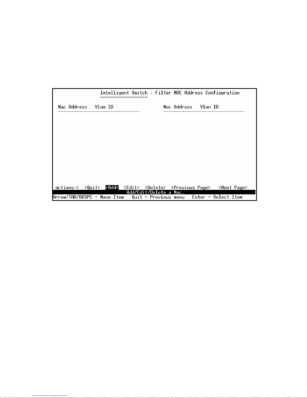
4.2.8.2. Filtering MAC Address
MAC address filtering allows the switch to drop unwanted traffic. Traffic is filtered based on the
destination addresses.
In this page user can add /modify /delete filter MAC address.
●
Add filter MAC address
Actions->
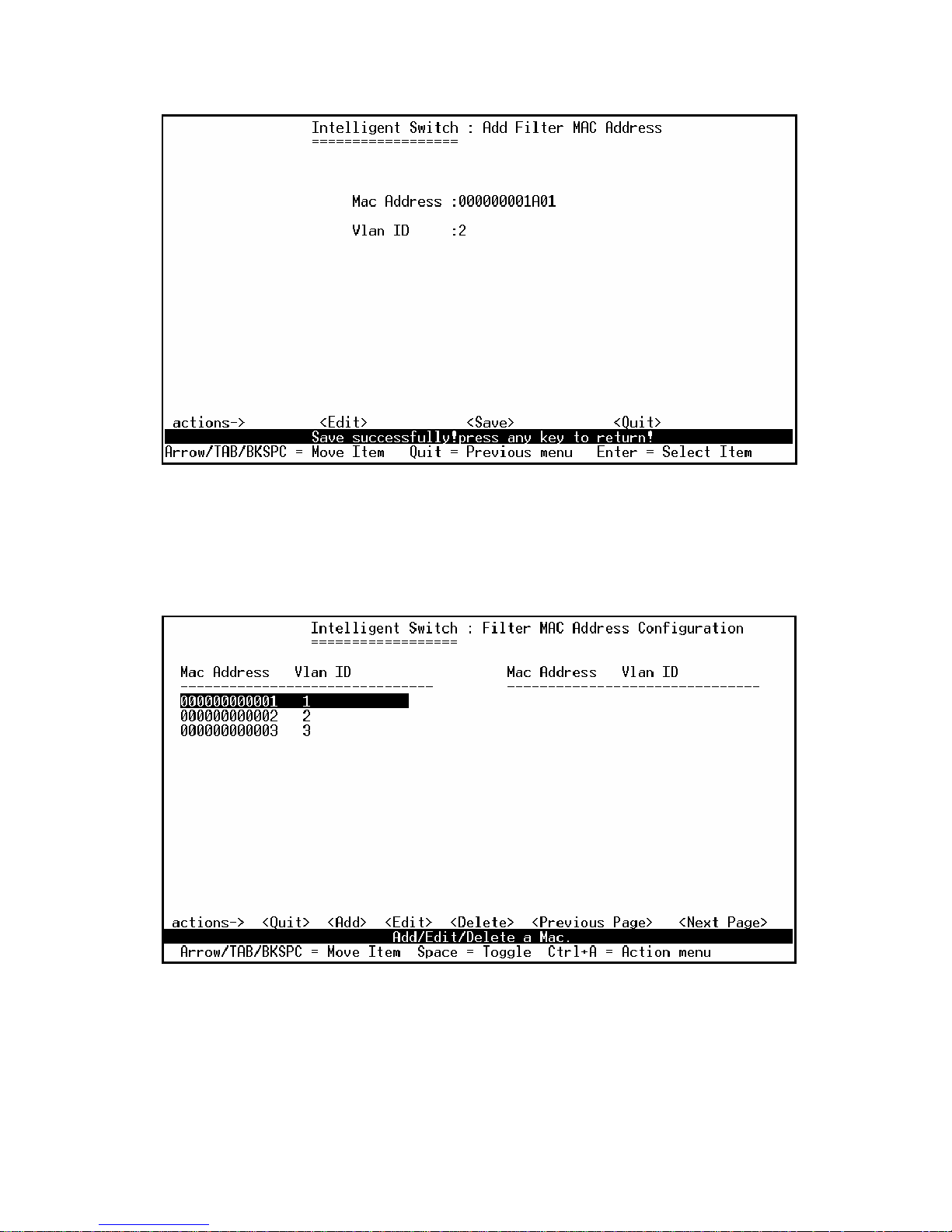
1. Press <Add> --> <Edit> key to add a filter MAC address.
2. MAC Address: Type the MAC address to filter.
3. Vlan ID: If tag-based (802.1Q) VLAN are set up on the switch, type the VID to associate with
the MAC address.
4. Press Ctrl+A to go back action menu line, and then select <Save> to save all configure value.
Page 84
- 84 -
●
Edit filter MAC address
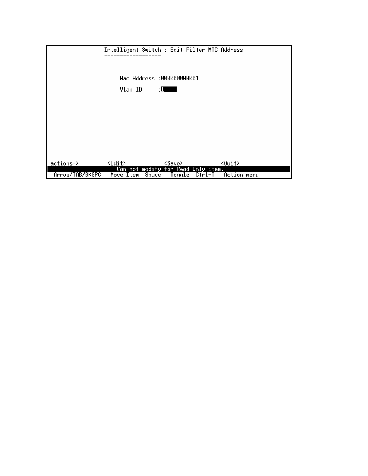
Actions->
1.
Press <Edit> key.
2. Choose the MAC address that you want to modify and then press enter.
3. Press <Edit> key to modify all the items.
4. Press Ctrl+A to go back action menu line, and then select <Save> to save all configure value.
Page 85
- 85 -
Page 86
- 86 -
●
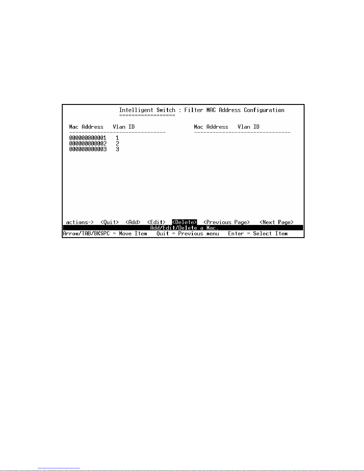
Delete filter MAC address
Actions->
1. Press <Delete> key to delete a filter MAC address.
2. Choose the MAC address that you want to delete and then press enter.
3. When pressing <Enter> once will complete deletion on delete mode.
Page 87
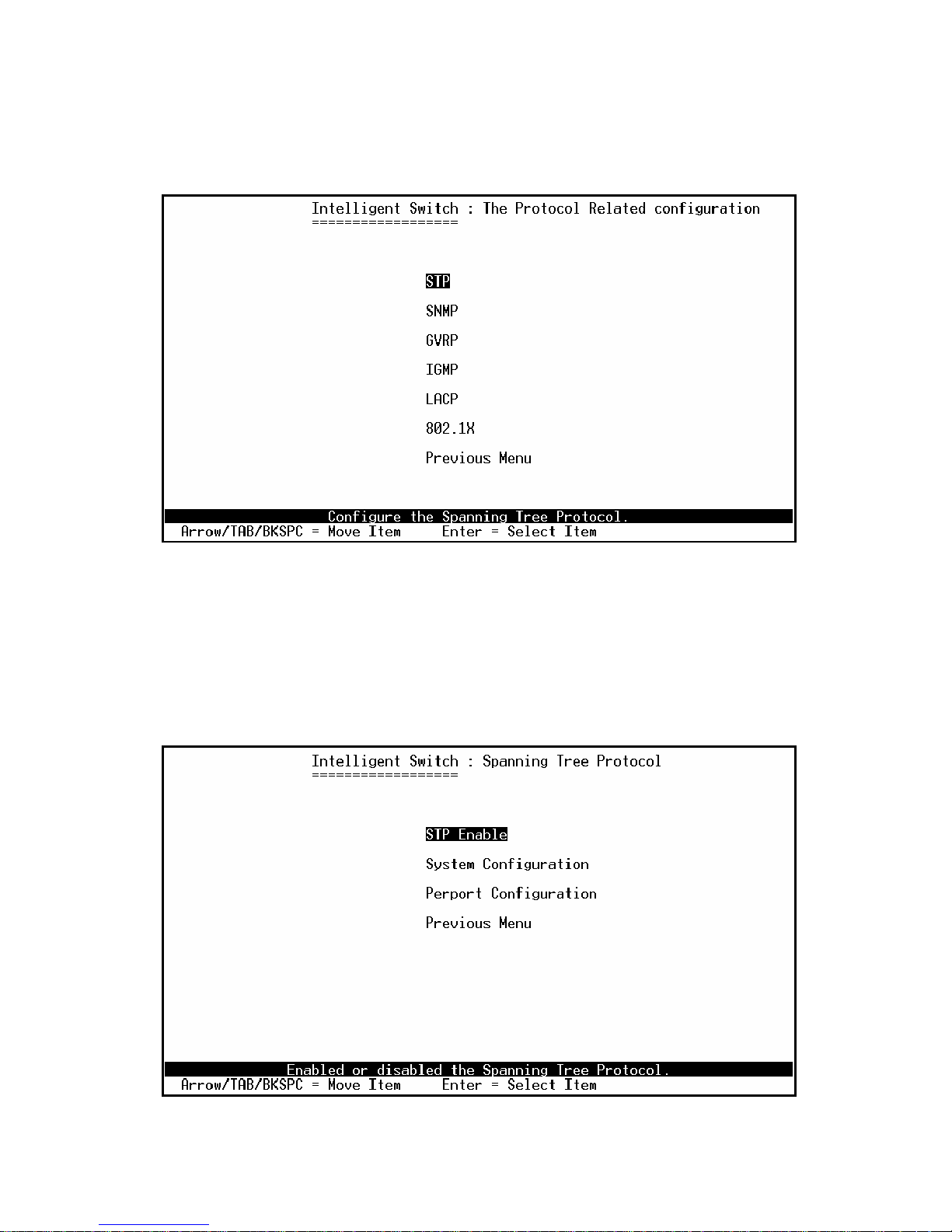
- 87 -
4.3. Protocol Related Configuration
4.3.1. STP
The Spanning-Tree Protocol (STP) is a standardized method (IEEE 802.1D) for avoiding loops in
switched networks. When STP enabled, to ensure that only one path at a time is active between any
two nodes on the network.
Page 88
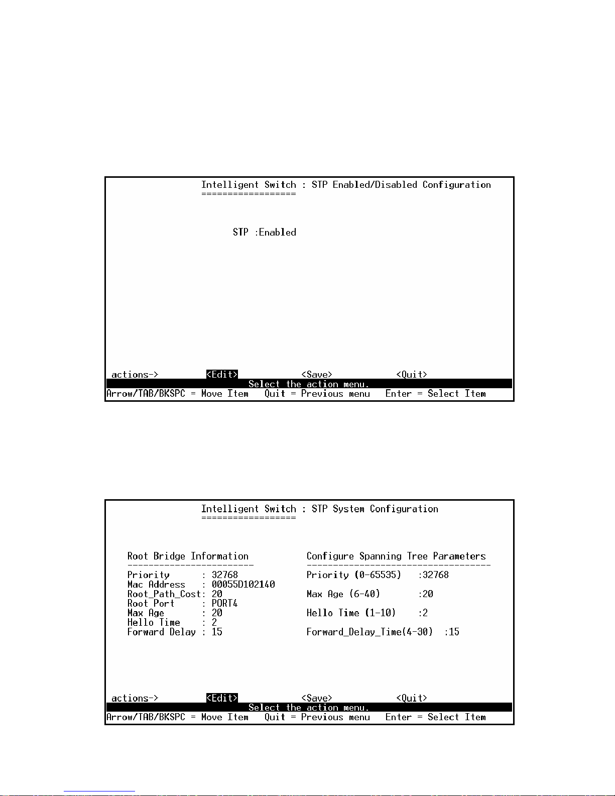
- 88 -
4.3.1.1. STP Enable
This page is showing the users how to enable or disable Spanning Tree function. Press Space key to
select enable or disable.
4.3.1.2. STP System Configuration
Page 89

- 89 -
Actions->
1. You can view spanning tree information about the Root Bridge on the left.
2. On the right, user can set new value for STP parameter.
NOTE: All about the parameter description please see the sections 2-4-8.
Page 90
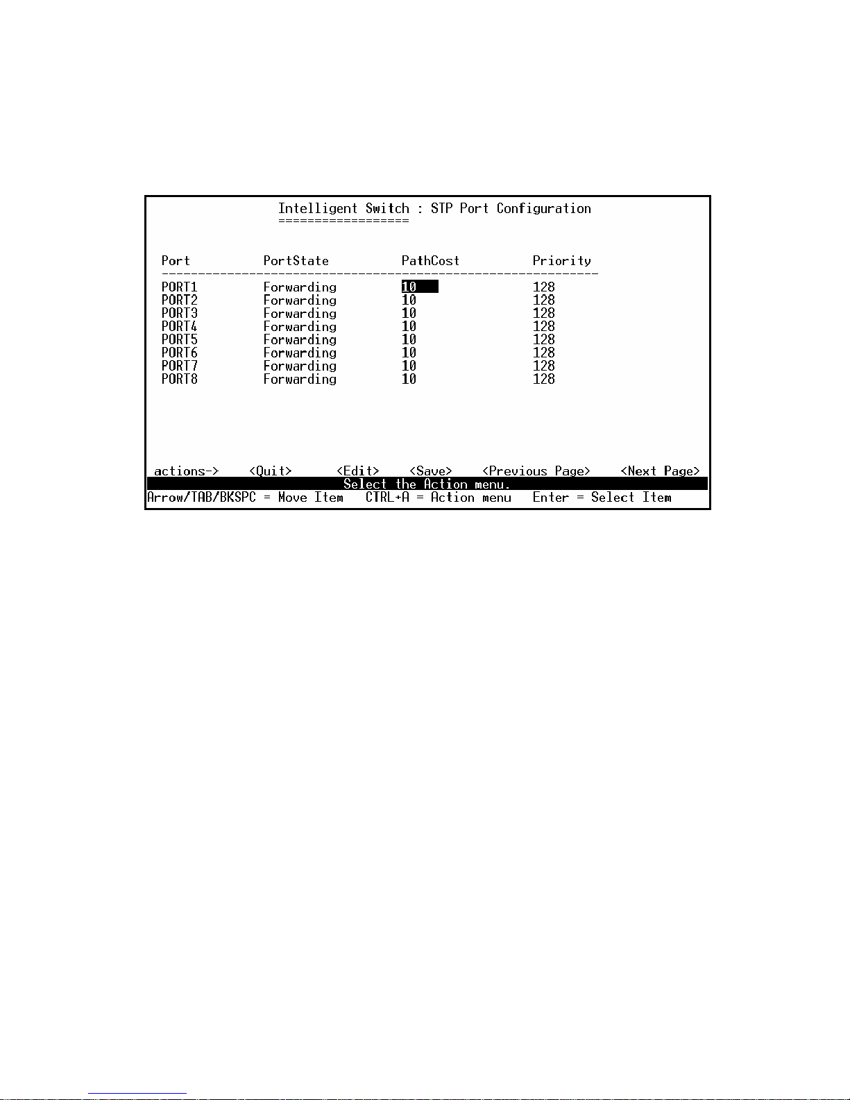
- 90 -
4.3.1.3. Purport Configuration
Actions->
1. PortState: Display spanning tree status about the switch for per port is forwarding or blocking.
2. Select <Edit>.
3. PathCost: Specifies the path cost of the port that switch uses to determine which port are the
forwarding ports.
4. Priority: This means priority port, you can make it more or less likely to become the root port.
5. Press Ctrl +A back to action menu line.
6. Select <Save> to save all configure value.
7. On the action menu line you can press <Next Page> to configure port9 ~ port26, press <Previous
Page> return to last page.
NOTE: All about the parameter description please see the sections 2-4-8.
Page 91
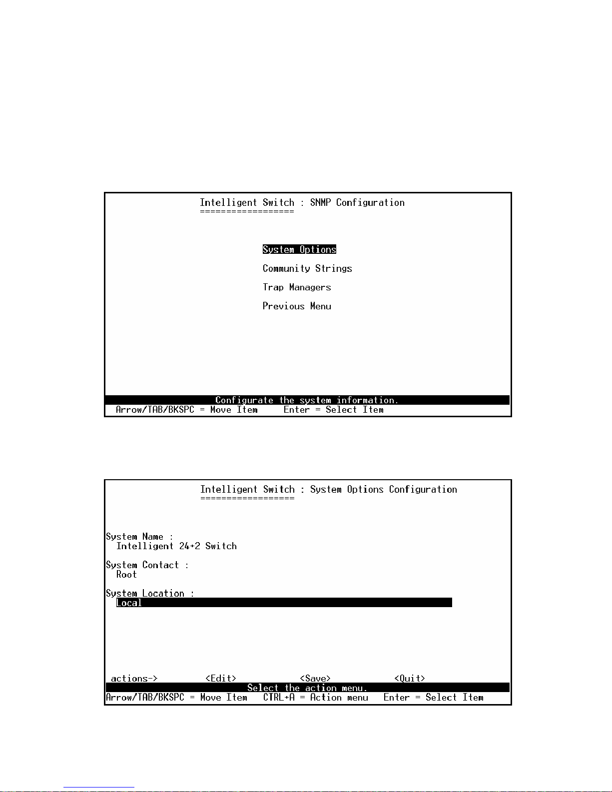
- 91 -
4.3.2. SNMP
Any Network Management running the simple Network Management Protocol (SNMP) can be
management the switch.
Use this page to define management stations as trap managers and to enter SNMP community strings.
User can also define a name, location, and contact person for the switch.
4.3.2.1. System Options
Actions->
Page 92

- 92 -
1. Press <Edit>.
2. System Name: Type a name to be used for the switch.
3. System Contact: Type the name of contact person or organization.
4. System Location: Type the location of the switch.
5. Press Ctrl+A go back action menu line.
6. Press <Save> to save the configure value.
Page 93
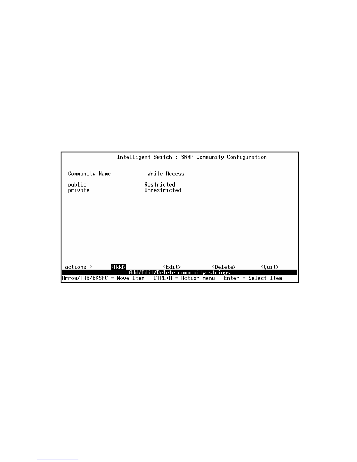
- 93 -
4.3.2.2. Community Strings
Use this page to Add/ Edit/ Delete SNMP community strings.
1. Community Name: The name of current strings.
2. Write Access: Enable the rights is read only or read-write.
Restricted: Read only, enables requests accompanied by this string to display MIB-object
information.
Unrestricted: Read write, enables requests accompanied by this string to display MIB-object
information and to set MIB objects.
Page 94
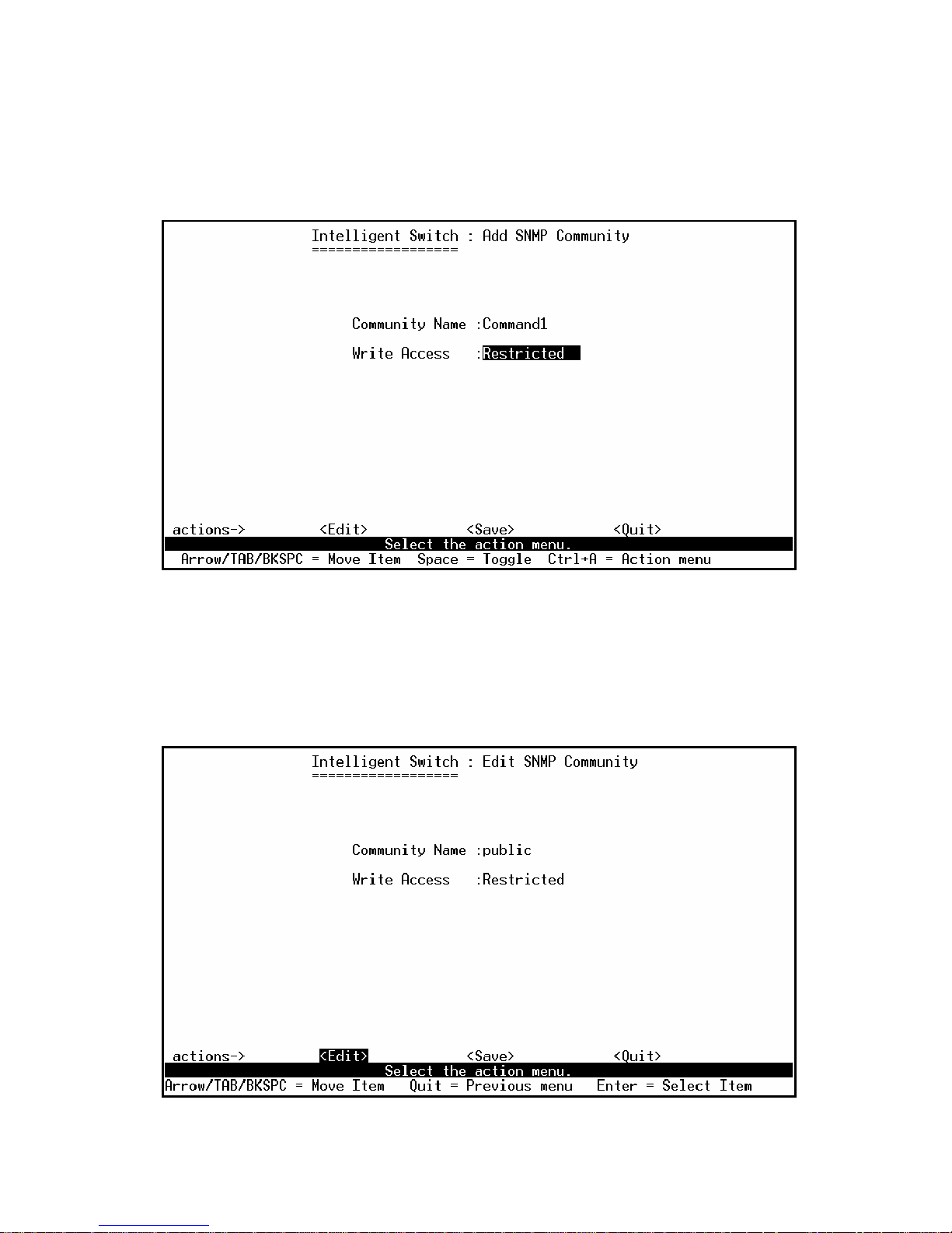
- 94 -
z Add Community Name
1. Press <Add> --> <Edit> key.
2. Community Name: Type the community name.
3. Write Access: Press Space key to select the right is restricted or unrestricted.
z Edit Community Name
1. Press <Edit> key, choose the item that you want to modify and then press Enter.
2. Community Name: Type the new name.
3. Write Access: Press <Space> key to change the right is restricted or unrestricted.
Page 95
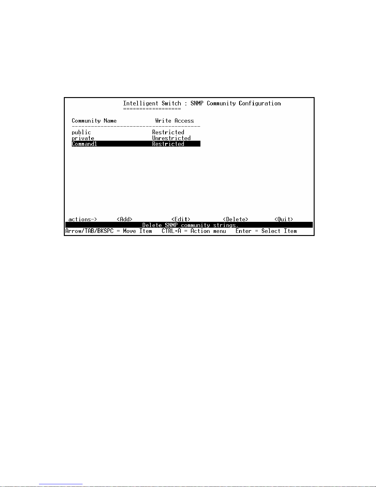
- 95 -
z Delete Community Name
1. Press <Delete> key.
2. Choose the community name that you want to delete and then press enter.
3. When pressing <Enter> once will complete deletion on delete mode.
Page 96
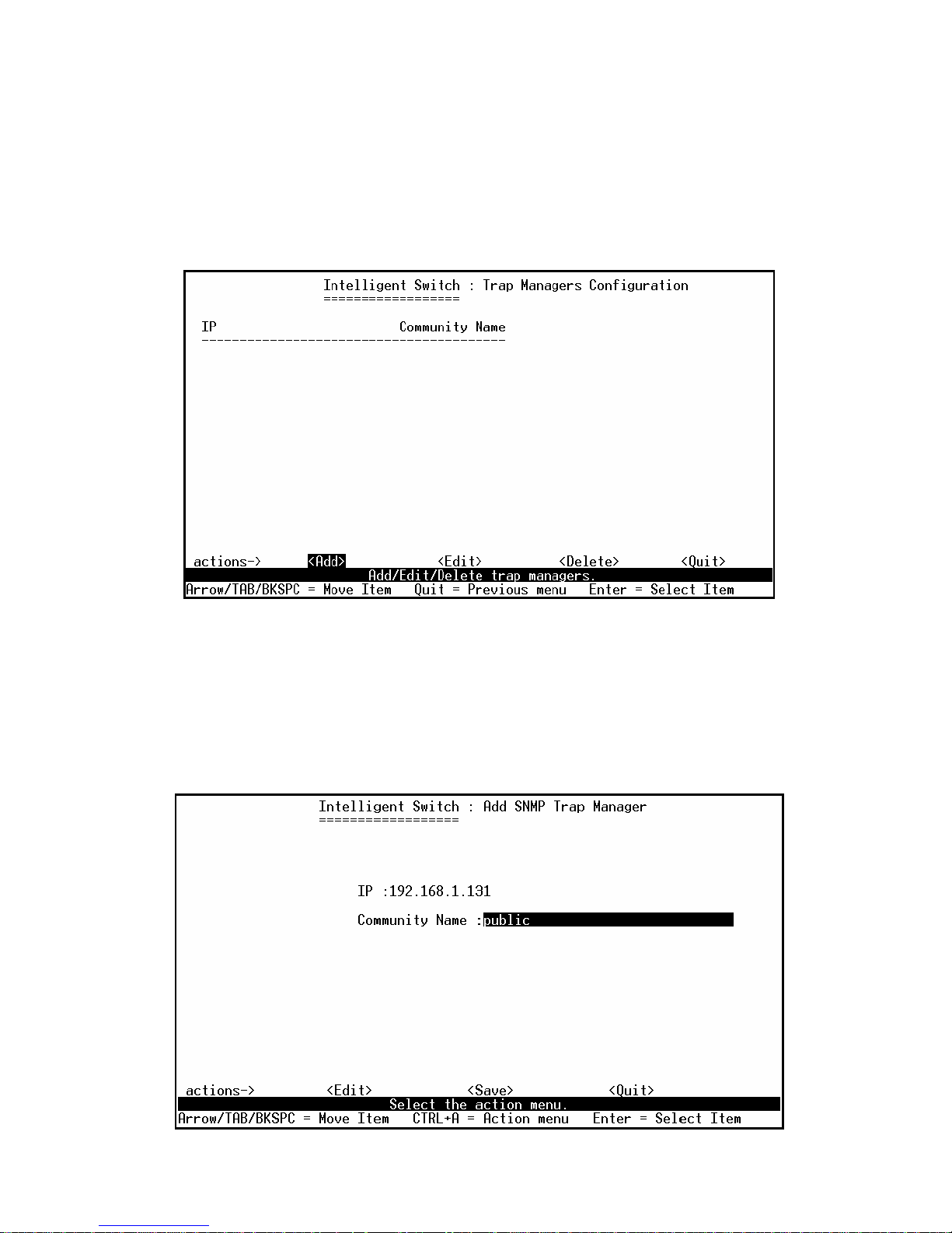
- 96 -
4.3.2.3. Trap Managers
A trap manager is a management station that receives traps, the system alerts generated by the switch.
If no trap manager is defined, no traps are issued. Create a trap manager by entering the IP address of
the station and a community string.
z Add SNMP trap manager
1. Press <Add> --> <Edit> to add the trap manager.
2. IP: Type the IP address.
3. Community Name: Type the community name.
4. Press Ctrl +A go to actions line, press <Save> key to save all configure.
Page 97
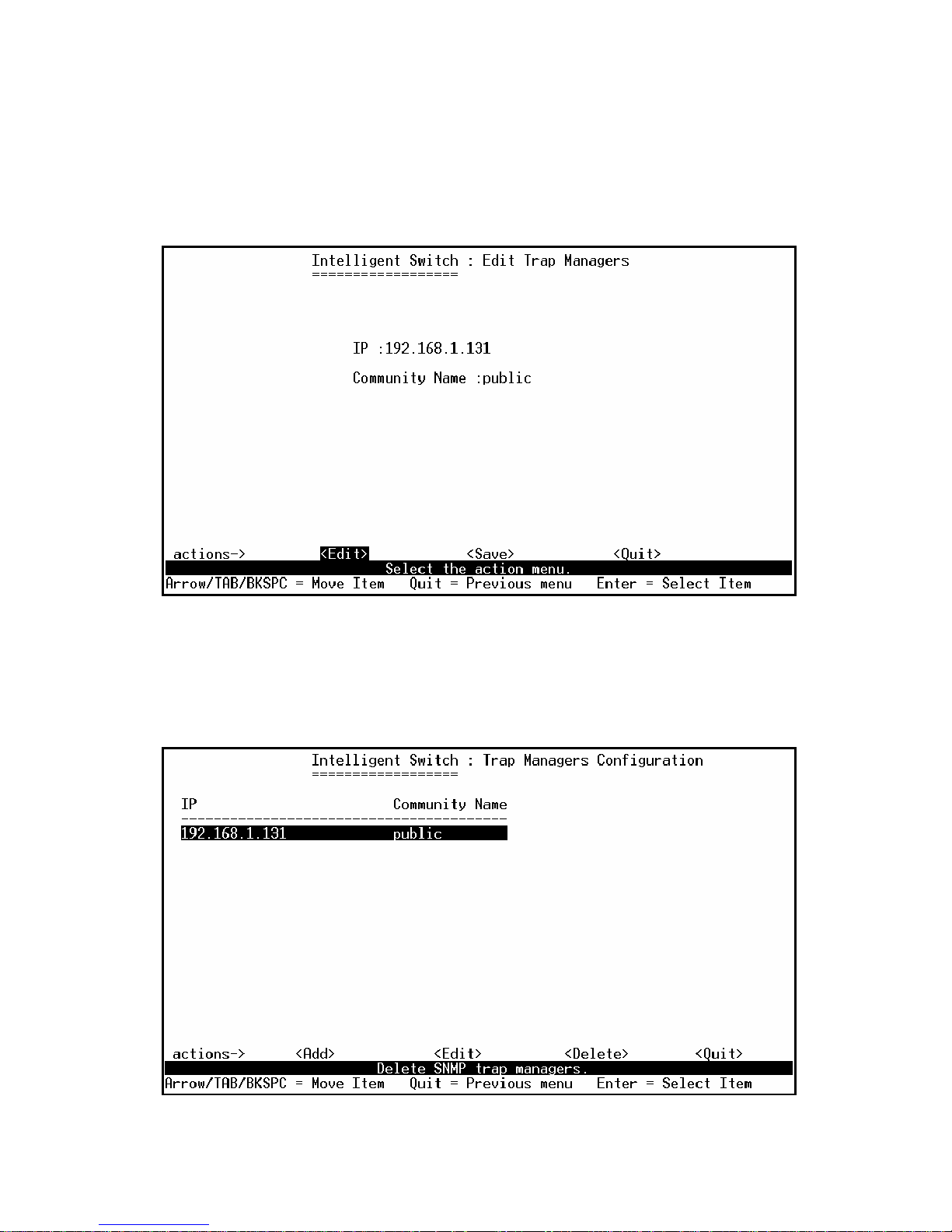
- 97 -
z Edit trap managers
1. Press <Edit> key, and then choose the item that you want to modify.
2. IP: Type the new IP address
3. Community Name: Type the community name.
4. Press Ctrl +A go to actions line, press <Save> key to save all configure.
z Delete trap manager
1. Press <Delete> key.
2. Choose the trap manager that you want to delete and then press enter.
3. When pressing <Enter> once will complete deletion on delete mode.
Page 98
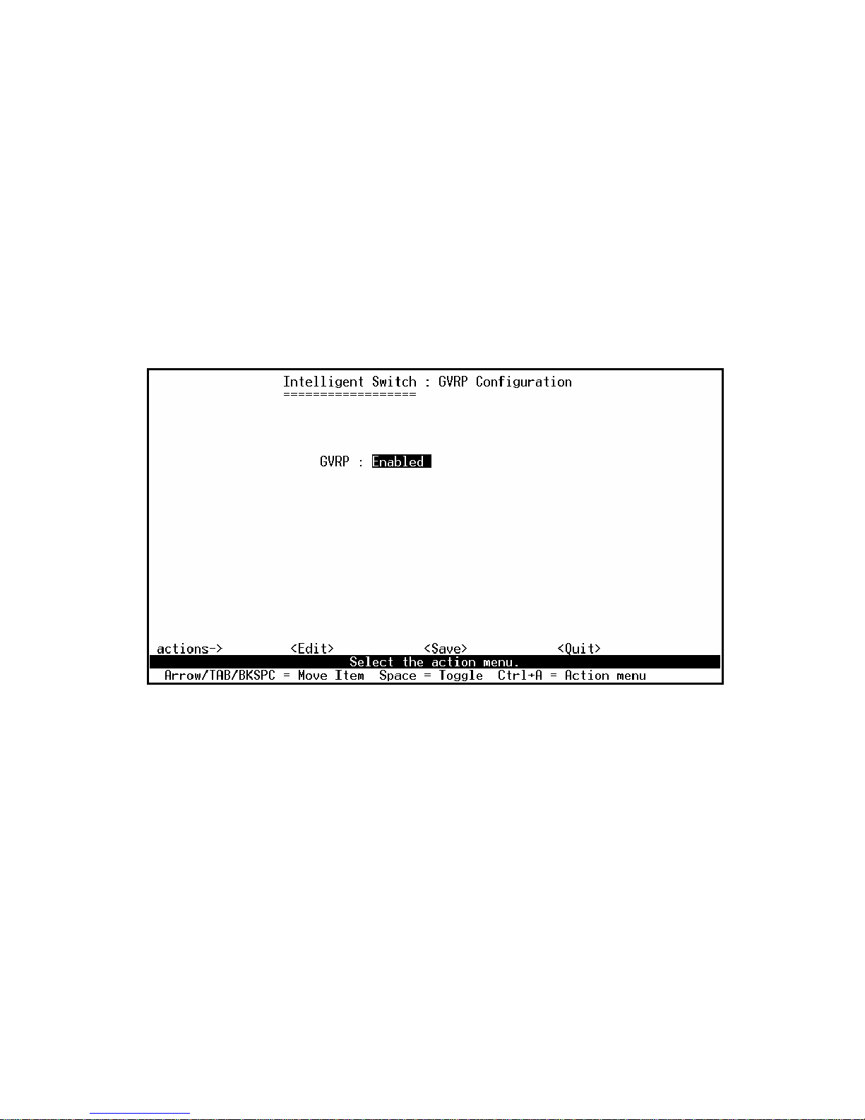
- 98 -
4.3.3. GVRP
GVRP (GARP [Generic Attribute Registration Protocol] VLAN Registration Protocol)
GVRP allows automatic VLAN configuration between the switch and nodes.
For example, if the switch is connected to a device with GVRP enabled, you can enable this setting to
allow dynamic VLAN configuration information to be processed by the switch.
If a device sends a GVRP request using the VID of a VLAN defined on the switch, the switch will
automatically add that device to the existing VLAN.
This page you can enable / disable the GVRP (GARP VLAN Registration Protocol) support.
Actions->
1. Select <Edit>.
2. Press Space key to choose Enabled / Disabled.
3. Press Ctrl+A back to action menu line.
4. Select <Save> to save configure value.
Note: GVRP must also be enabled on participating network nodes.
Page 99
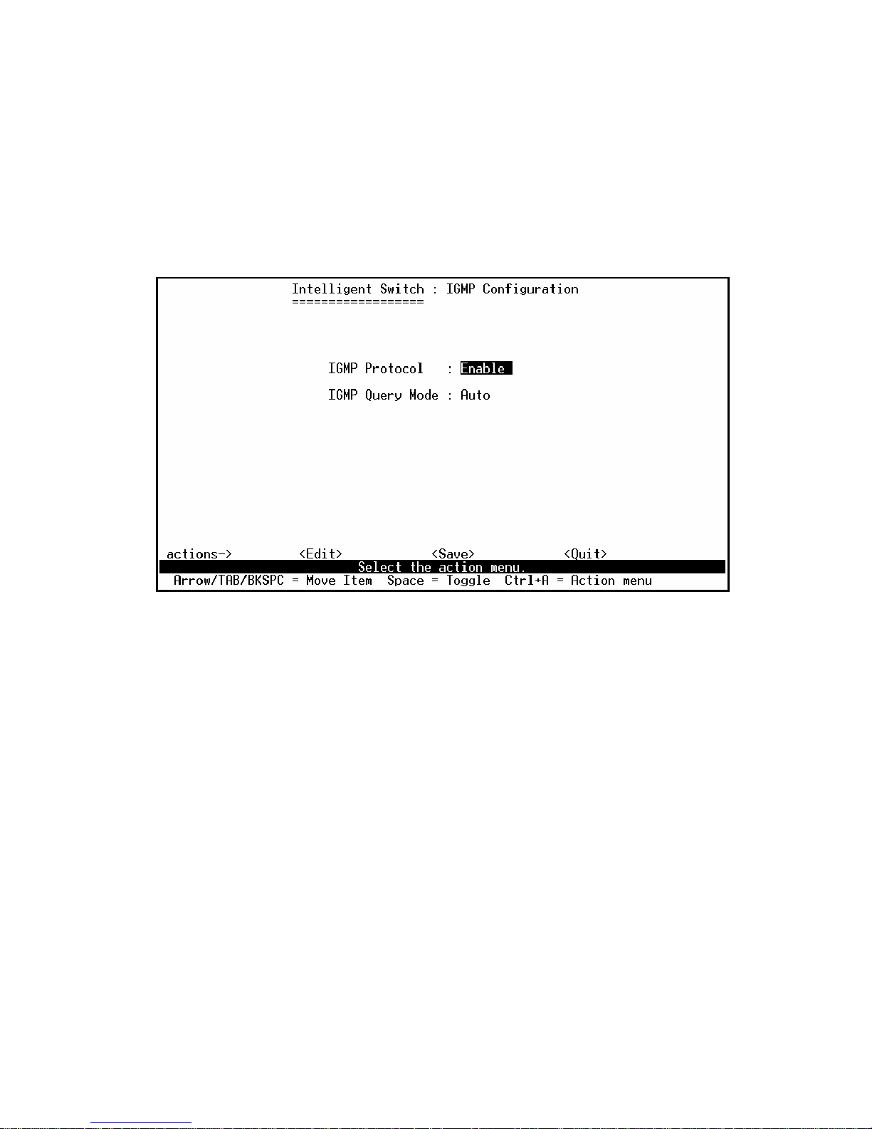
- 99 -
4.3.4. IGMP
The Internet Group Management Protocol (IGMP) is an internal protocol of the Internet Protocol (IP)
suite.
This page you can enable / disable the IGMP support.
Actions->
1. Select <Edit>.
2. IGMP Protocol: Press Space key to choose Enable / Disable.
3. IGMP Query Mode: Press Space key to choose Auto / Enable /Disable.
4. Press Ctrl+A go back action menu line.
5. Select <Save> to save configure value.
Page 100

- 100 -
4.3.5. LACP (Link Aggregation Control Protocol)
This page can configure and view all the LACP status.
Note: All ports support LACP dynamic trunk group. If connecting to the device that also supports
LACP, the LACP dynamic trunk group will be created automatically.
4.3.5.1. Working Port Setting
This page can set the actually work ports in trunk group.
 Loading...